1982 CHEVROLET CAMARO clutch
[x] Cancel search: clutchPage 306 of 875

GM – CAMARO 1982-1992 – Repair Guide (Checked by WxMax) 306
As the speed of the turbine increases, th
e fluid spins faster and faster in the
direction of engine rotation. As a result, t he ability of the stator to redirect the
fluid flow is reduced. Under cruising conditions, the stator is eventually forced to
rotate on its one-way clutch in the dire ction of engine rotation. Under these
conditions, the torque converter begins to behave almost like a solid shaft, with
the torus and turbine speeds being almost equal.
PLANETARY GEARBOX
The ability of the torque converter to mult iply engine torque is limited. Also, the
unit tends to be more efficient when the turbine is rotating at relatively high
speeds. Therefore, a planetar y gearbox is used to carry the power output of the
turbine to the driveshaft.
Fig. 2: Planetary gears work in a sim ilar fashion to manual transmission gears,
but are composed of three parts
Planetary gears function very similarly to conventional transmission gears.
However, their construction is different in that three elements make up one gear
system, and, in that all three elements ar e different from one another. The three
elements are: an outer gear that is shaped like a hoop, with teeth cut into the
inner surface; a sun gear, mounted on a sha ft and located at the very center of
Page 308 of 875

GM – CAMARO 1982-1992 – Repair Guide (Checked by WxMax) 308
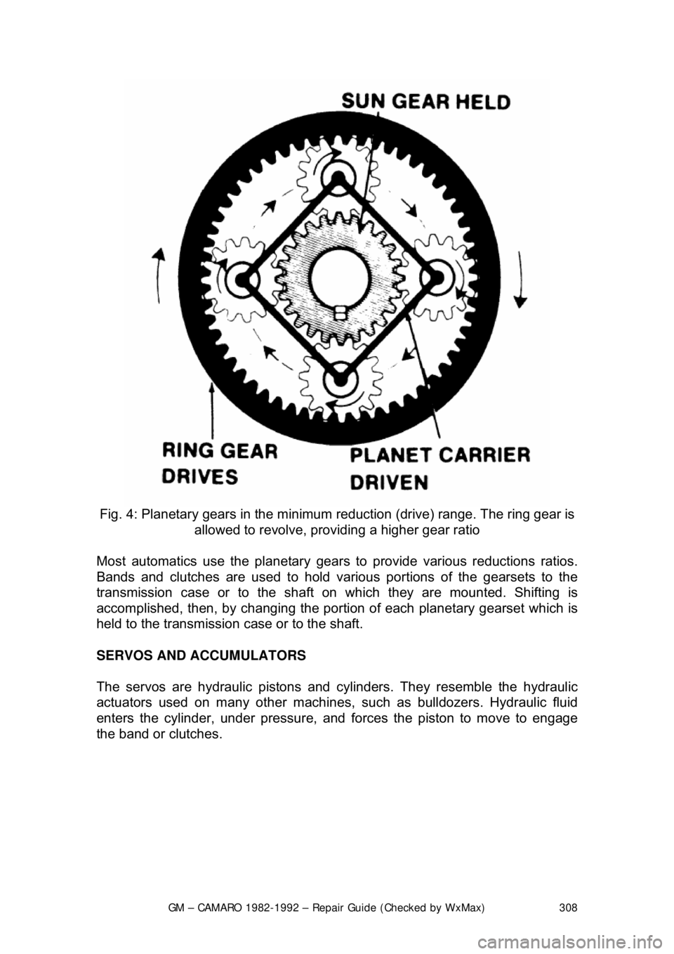
Fig. 4: Planetary gears in the minimum reduction (drive) range. The ring gear is
allowed to revolve, providing a higher gear ratio
Most automatics use the pl anetary gears to provide various reductions ratios.
Bands and clutches are used to hold va rious portions of the gearsets to the
transmission case or to the shaft on which they are mounted. Shifting is\
accomplished, then, by c hanging the portion of each planetary gearset which is
held to the transmission case or to the shaft.
SERVOS AND ACCUMULATORS
The servos are hydraulic pistons and cylinders. They resemble the hydrau\
lic
actuators used on many other machines, such as bulldozers. Hydraulic fluid
enters the cylinder, under pressure, and fo rces the piston to move to engage
the band or clutches.
Page 310 of 875

GM – CAMARO 1982-1992 – Repair Guide (Checked by WxMax) 310
modulator pressure rises as the thro
ttle is opened wider. By responding to these
two pressures, the shift valves caus e the upshift points to be delayed with
increased throttle opening to make the bes t use of the engine's power output.
Most transmissions also make use of an auxiliary circuit for downshifting. This
circuit may be actuated by the throttle linkage the vacuum line which actuates
the modulator, by a cable or by a solenoid. It applies pressure to a special
downshift surface on the shift valve or valves.
The transmission modulator also governs the line pressure, used to actuate the
servos. In this way, the clutches and bands will be actuated with a force
matching the torque output of the engine.
IDENTIFICATION
Two types of transmissions are used on th e vehicles; Turbo Hydra-Matic 200C
3-speed and Turbo Hydra-Matic 700-R4 4-speed. Beginning in 1991, the 700-
R4 was redesignated the 4L60.
FLUID PAN
REMOVAL, FLUID/FILTER CH ANGE, & INSTALLATION
Refer to General Information & Ma intenance for fluid pan procedures.
ADJUSTMENTS
BANDS
There are no band adjustments possible or required.
Page 345 of 875

GM – CAMARO 1982-1992 – Repair Guide (Checked by WxMax) 345
operation is required of it. Thus, little a
llowance for air circulation is required,
and the windings can be built into a very small space.
The starter solenoid is a magnetic dev ice which employs the small current
supplied by the starting switch circuit of the ignition switch. This magnetic action
moves a plunger which mechanically engages the starter and electrically closes
the heavy switch which connects it to t he battery. The starting switch circuit
consists of the starting switch cont ained within the ignition switch, a
transmission neutral safety switch or clutch pedal switch, and the wiring
necessary to connect these with the starter solenoid or relay.
A pinion, which is a small gear, is m ounted to a one-way drive clutch. This
clutch is splined to the starter armature shaft. When the ignition switch is moved
to the start position, the solenoid plunger slides the pinion toward the flywheel
ring gear via a collar and spring. If t he teeth on the pinion and flywheel match
properly, the pinion will engage the flywheel immediately. If the gear teeth butt
one another, the spring will be compressed and will force the gears to mesh as
soon as the starter turns far enough to a llow them to do so. As the solenoid
plunger reaches the end of it s travel, it closes the contacts that connect the
battery and starter and then the engine is cranked.
As soon as the engine star ts, the flywheel ring gear begins turning fast enough
to drive the pinion at an ex tremely high rate of speed. At this point, the one-way
clutch begins allowing the pi nion to spin faster than the starter shaft so that the
starter will not operate at excessive speed. When the i gnition switch is released
from the starter position, the solenoid is de-energized, and a spring contained
within the solenoid assembly pulls the gear out of mesh and interrupts the
current flow to the starter.
Some starters employ a separate relay, mounted away from the starter, to
switch the motor and solenoid current on and off. The relay thus replaces the
solenoid electrical switch, but does not eliminate the need for a solenoid
mounted on the starter used to mechanica lly engage the starter drive gears.
The relay is used to reduce the amount of current the starting switch must carry.
THE CHARGING SYSTEM
The automobile charging system provides electrical power for operation of the
vehicle's ignition and star ting systems and all the electrical accessories. The
battery serves as an electrical surge or storage tank, storing (in chemical form)
the energy originally pr oduced by the engine driven gen erator. The system also
provides a means of regulating alternat or output to protect the battery from
being overcharged and to avoid excess ive voltage to the accessories.
The storage battery is a chemical device in corporating parallel lead plates in a
tank containing a sulfuric acid-water solution. Adjacent plates are slightly
dissimilar, and the chemical reaction of the two dissimilar plates produces
electrical energy when the battery is connected to a load such as the starter
motor. The chemical reaction is reversible, so that when the generator i\
s
producing a voltage (electrical pressure ) greater than that produced by the
Page 364 of 875

GM – CAMARO 1982-1992 – Repair Guide (Checked by WxMax) 364
5. Drain the radiator and remove t
he radiator hoses. Disconnect the heater
hoses and the transmission cooler lines.
6. Remove the upper half of the radi ator shroud, if equipped with a manual
transmission. Remove the radiator and fan shroud assembly, if equipped
with an automatic transmission.
7. Disconnect the throttle linkage, includi ng the cruise control detent cable.
8. Remove the air conditioning compressor and lay aside.
Do not disconnect the air conditioning lines.
9. Disconnect the power steering pump and drain the fluid into a suitable
container. Remove the vacuum brake booster line.
10. Remove the distributor cap and spark plug wires.
11. Disconnect the engine electrical connection at the bulkhead connection
and disconnect any necessary vacuum hoses.
12. Working inside the vehicle, re move the right-hand hush panel and
disconnect the ECM harness at the EC M. Raise and safely support the
vehicle. Remove the right fenderwell splash shield and feed the harness
through the fenderwell.
13. Disconnect the exhaust pipes at the exhaust manifolds and remove
exhaust system from the vehicle.
14. Remove the flywheel cover and remo ve the converter bolts, if equipped
with automatic transmission.
15. Disconnect the transmission an d starter wire connections.
16. Remove the bellhousing and t he motor mount through-bolts.
17. Disconnect the clutch fork return spring, if equipped with a manual
transmission. Lower the vehicle.
18. Relieve the fuel system pressu re. Disconnect the fuel lines.
19. Support the transmission with a suit able jack. Attach an engine lifting
device.
20. Remove the engine assembly.
To install: 21. Position the engine assembly in the vehicle.
22. Attach the motor mount to engine br ackets and lower the engine in place.
Remove the engine lifting device and the transmission jack.
23. Raise and support the vehicle safely.
24. Install the motor mount through-bolts and tighten the nuts to specification. Install t he bellhousing bolts and tight en to 35 ft. lbs. (47
Nm).
25. On vehicles with automatic transmissi on, install the converter to flywheel
attaching bolts to 46 ft. lbs. (63 Nm).
26. Install the flywheel splash shield and tighten to 89 inch lbs. (10 Nm).
Install the clutch return spring, if equipped with manual transmission.
27. Connect the starter wires and the fuel lines.
28. Install the exhaust system.
29. Lower the vehicle.
30. Install the power steering pump and the air conditioning compressor.
Page 405 of 875

GM – CAMARO 1982-1992 – Repair Guide (Checked by WxMax) 405
3. Remove the fan-to-water pum
p attaching bolts or nuts.
4. Remove the fan belts.
5. Remove the cooling fan and clut ch assembly. Separate the clutch
assembly from the fan.
Store the clutch in an upright position to prevent seal leakage.
6. Installation is the revers e of the removal procedure.
WATER PUMP
REMOVAL & INSTALLATION
CAUTION - When draining the coolant, keep in mind that cats and dogs are
attracted by the ethylene gl ycol antifreeze, and are quite likely to drink any that
is left in an uncovered container or in puddles on the ground. This will prove
fatal in sufficient quantity. Always drai n the coolant into a sealable container.
Coolant should be reused unless it is contaminated or several years old.
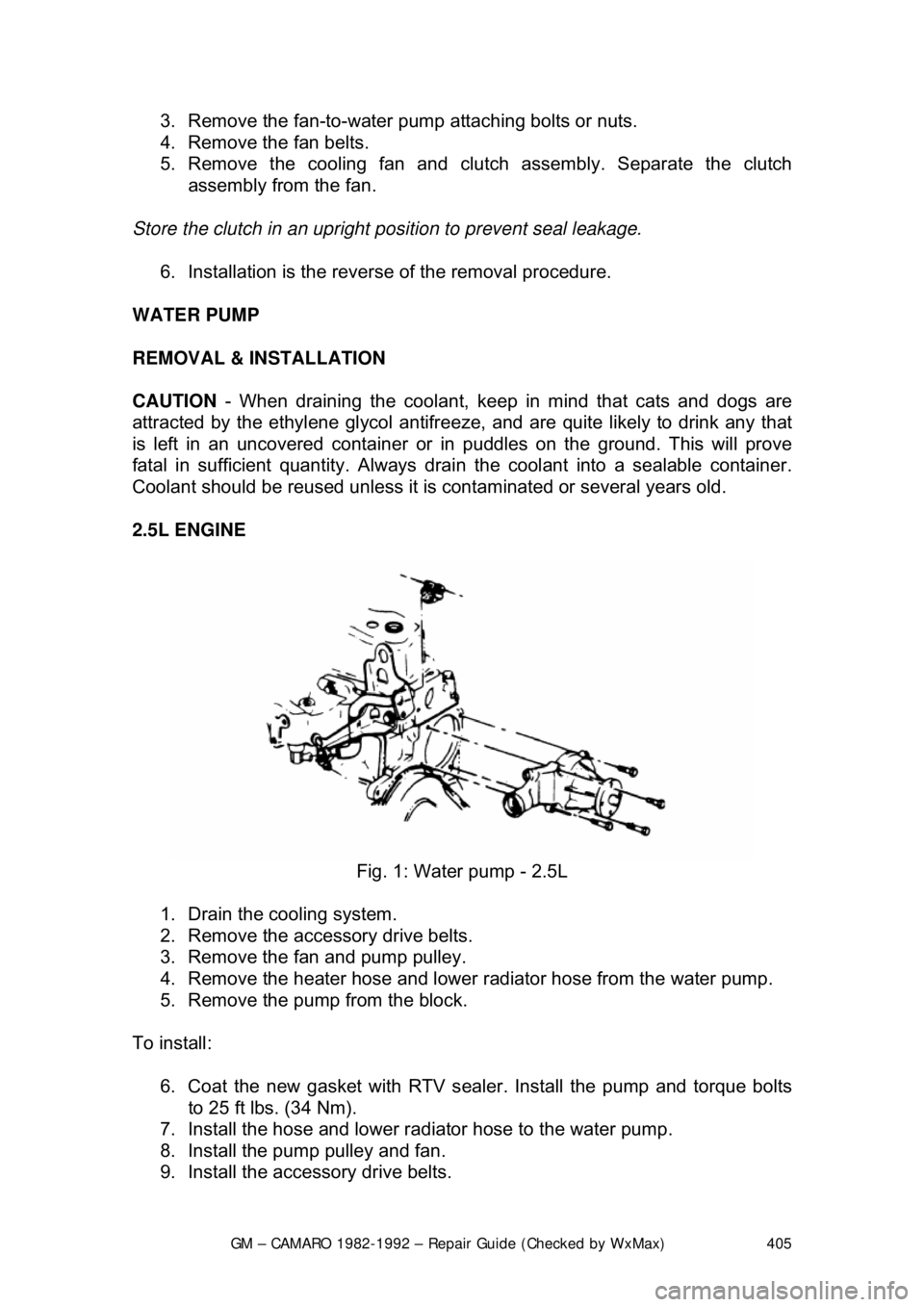
2.5L ENGINE
Fig. 1: Water pump - 2.5L
1. Drain the cooling system.
2. Remove the accessory drive belts.
3. Remove the fan and pump pulley.
4. Remove the heater hose and lower r adiator hose from the water pump.
5. Remove the pump from the block.
To install: 6. Coat the new gasket with RTV sealer . Install the pump and torque bolts
to 25 ft lbs. (34 Nm).
7. Install the hose and lower radi ator hose to the water pump.
8. Install the pum p pulley and fan.
9. Install the accessory drive belts.
Page 451 of 875

GM – CAMARO 1982-1992 – Repair Guide (Checked by WxMax) 451
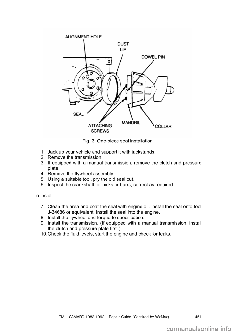
Fig. 3: One-piece seal installation
1. Jack up your vehicle and support it with jackstands.
2. Remove the transmission.
3. If equipped with a manual transmission, remove the clutch and pressure
plate.
4. Remove the flywheel assembly.
5. Using a suitable tool, pry the old seal out.
6. Inspect the crankshaft for nicks or burrs, correct as required.
To install: 7. Clean the area and coat the seal with eng ine oil. Install the seal onto tool
J-34686 or equivalent. Install the seal into the engine.
8. Install the flywheel and torque to specification.
9. Install the transmission. (If equipped with a manual transmission, install
the clutch and pressure plate first.)
10. Check the fluid levels, star t the engine and check for leaks.
Page 799 of 875

GM – CAMARO 1982-1992 – Repair Guide (Checked by WxMax) 799
The master cylinder is located in
the left rear section of the engine
compartment. The brake master cylinder consists of an aluminum body and a
translucent nylon reservoir with minimum fill indicators.
1. Check the master cylinder body for cracks. Inspect the area around the
master cylinder for brake fluid. Leaks are indicated if there is at least a
drop of fluid. A damp condition is not normal.
2. Inspect the level of the brake fluid to assure it is at the correct height.
Clean the top of the reservoir cap so t hat all dirt is removed. Remove the
cap(s) or reservoir cover and the reservoir diaphragm.
3. Inspect the brake fluid level. Add clean DOT-3 brake fluid as required to
bring the fluid level to the line located inside the neck of the reservoir fill
opening.
4. Install the reservoir cap.
WARNING - Any sudden decrease in the fluid level indicates a possible leak in
the system and should be check ed out immediately. Do not allow brake fluid to
spill on the vehicle's finish; it will remove the paint. In case of a spill, flush the
area with water and mild soap.
HYDRAULIC CLUTCH SYSTEM
FLUID RECOMMENDATIONS
• 1982-1991 - Delco Supreme II Brake fl uid or an equivalent fluid that
meets DOT-3 specifications
• 1992 - Hydraulic clutch fluid, GM part number 12345347 or equivalent
LEVEL CHECK
The clutch master cylinder is normally lo cated below the brake master cylinder.
The reservoir for it is located right bes ide the brake master cylinder and is made
of translucent nylon. The fl uid level of the reservoir sh ould be kept near the top
of the observation window. Before removing the cap to the reservoir, clean all
dirt from the area. This will prevent syst em contamination due to particles falling
into the reservoir when the caps are removed.
POWER STEERING PUMP
FLUID RECOMMENDATIONS
• GM power steering fluid, or equivalent.