1982 CHEVROLET CAMARO shift
[x] Cancel search: shiftPage 295 of 875

GM – CAMARO 1982-1992 – Repair Guide (Checked by WxMax) 295
of the spring bow outward, pushing the pre
ssure plate into closer contact with
the clutch disc. As the disc and plate mo ve closer together, friction between the
two increases and slippage is reduced until, when full spring pressure is applied
(by fully releasing the pedal) the speed of the disc and plate are the same. This
stops all slipping, creating a direct connection between the plate and disc which
results in the transfer of power from t he engine to the transmission. The clutch
disc is now rotating with the pressure plate at engine speed and, because it is
splined to the transmission shaft, the shaft now turns at the same engine speed.
The clutch is operating properly if: 1. It will stall the engine when released with the vehicle held stationary.
2. The shift lever can be moved freel y between 1st and reverse gears when
the vehicle is stationary and the clutch disengaged.
APPLICATION
All 1982-83 vehicles use a mechanical (non-hydraulic) clutch; 1984-92 models
use a hydraulic clutch. With the hydraulic clutch, no adjustment of the clutch
pedal or the linkage is required. On t he mechanical type, the only required
adjustment is to maintain the proper clutch pedal freeplay. The freeplay\
adjustment is very important, for it determines the engaging and disengaging
characteristics of the clutch assembly.
The clutch assembly consists of: a flywheel, a pressure plate, a throwout
bearing and fork, a clutch pedal, and an actuating lever (non-hydraulic) or a
master cylinder/slave cylinder (hydraulic).
The hydraulic system utilizes a remote re servoir which is mounted to the power
brake booster, a master cy linder mounted to the cowl p anel and a slave cylinder
that is mounted to the bell housing. Th e system is operated directly by the
clutch pedal. When adding fl uid to the reservoir, always use a type which meets
DOT 3 specifications.
CAUTION - The clutch driven disc contains asbestos, which has been
determined to be a cancer causing agen t. Never clean clutch surfaces with
compressed air! Avoid inhaling any dus t from any clutch surface! When
cleaning clutch surfaces, use a commercia lly available brake cleaning fluid.
FREE-PLAY ADJUSTMENT
MECHANICAL LINKAGE 1. Disconnect the return sp ring at the clutch fork.
2. Hold the pedal against the rubber bumper on the dash brace.
3. Push the clutch fork so that th e throwout bearing lightly contacts the
pressure plate fingers.
Page 300 of 875

GM – CAMARO 1982-1992 – Repair Guide (Checked by WxMax) 300
Fig. 1: Clutch assembly
5. Install an alignment tool to support the clutch assembly during removal.
Mark the flywheel and clutch cover for reinstallation, if they do not
already have X marks.
6. Loosen the clutch-to-flywheel attachi ng bolts evenly, one turn at a time,
until spring pressure is released. Remo ve the bolts and clutch assembly.
To install: 7. Clean the pressure plate and flywheel face.
8. Support the clutch di sc and pressure plate with an alignment tool. The
driven disc is installed with the damper springs on the transmission side.
9. Turn the clutch assembly until t he mark on the cover lines up with the
mark on the flywheel, then install t he bolts. Tighten down evenly and
gradually to avoid distortion.
10. Remove the alignment tool.
11. Lubricate the ball socket and fork fi ngers at the release bearing end with
high melting point greas e. Lubricate the recess on the inside of the
throwout bearing and throwout fork groove with a light coat of graphite
grease.
12. Install the clutch fork and dust boot into the housing. Install the throwout
bearing to the throwout fork. Insta ll the flywheel housing. Install the
transmission.
13. Connect the fork push rod and spri ng. Lubricate the spring and pushrod
ends.
14. Adjust the shift linkage and clutch pedal free-play.
Page 304 of 875

GM – CAMARO 1982-1992 – Repair Guide (Checked by WxMax) 304
Never release a depressed clutch pedal
with the bleeder screw open or air will
be drawn into the system.
AUTOMATIC TRANSMISSION
UNDERSTANDING AUTOMATIC TRANSMISSIONS
The automatic transmission allows eng ine torque and power to be transmitted
to the rear wheels within a narrow range of engine operating speeds. It will
allow the engine to turn fast enough to produce plenty of power and torque at
very low speeds, while keeping it at a s ensible rpm at high vehicle speeds (and
it does this job without driv er assistance). The transmission uses a light fluid as
the medium for the transmission of power. This fluid also works in the operation
of various hydraulic control circui ts and as a lubricant. Because the
transmission fluid performs all of thes e functions, trouble within the unit can
easily travel from one part to another. For this reason, and because of the
complexity and unusual oper ating principles of the transmission, a very sound
understanding of the basic principles of operation will simplify troubleshooting.
TORQUE CONVERTER
The torque converter replaces the convent ional clutch. It has three functions:
1. It allows the engine to idle with t he vehicle at a standstill, even with the
transmission in gear.
2. It allows the transmission to shi ft from range-to-range smoothly, without
requiring that the driver close the throttle during the shift.
3. It multiplies engine torque to an incr easing extent as vehicle speed drops
and throttle opening is increased. This has the effect of making the
transmission more responsive and redu ces the amount of shifting
required.
The torque converter is a metal case which is shaped like a sphere that
has been flattened on opposite sides. It is bolted to the rear end of the
engine's crankshaft. Generally, the ent ire metal case rotates at engine
speed and serves as the engine's flywheel.
The case contains three sets of bl ades. One set is attached directly to
the case. This set forms the torus or pump. Another set is directly
connected to the output shaft, and forms the turbine. The third set is
mounted on a hub which, in turn, is mounted on a stationary shaft
through a one-way clutch. This third set is known as the stator.
A pump, which is driven by the conv erter hub at engine speed, keeps the
torque converter full of transmission fluid at all times. Fluid flows
continuously through the unit to provide cooling.
Under low speed acceleration, the tor que converter functions as follows:
Page 308 of 875

GM – CAMARO 1982-1992 – Repair Guide (Checked by WxMax) 308
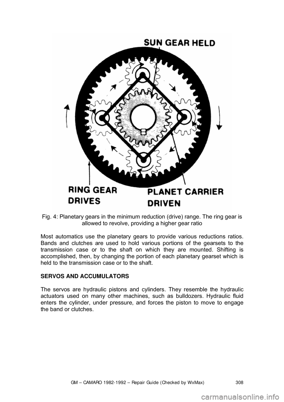
Fig. 4: Planetary gears in the minimum reduction (drive) range. The ring gear is
allowed to revolve, providing a higher gear ratio
Most automatics use the pl anetary gears to provide various reductions ratios.
Bands and clutches are used to hold va rious portions of the gearsets to the
transmission case or to the shaft on which they are mounted. Shifting is\
accomplished, then, by c hanging the portion of each planetary gearset which is
held to the transmission case or to the shaft.
SERVOS AND ACCUMULATORS
The servos are hydraulic pistons and cylinders. They resemble the hydrau\
lic
actuators used on many other machines, such as bulldozers. Hydraulic fluid
enters the cylinder, under pressure, and fo rces the piston to move to engage
the band or clutches.
Page 309 of 875

GM – CAMARO 1982-1992 – Repair Guide (Checked by WxMax) 309
Fig. 5: Servos, operated by pressure, ar e used to apply or release the bands, to
either hold the ring gear or allow it to rotate
The accumulators are used to cushi on the engagement of the servos. The
transmission fluid must pass through the ac cumulator on the way to the servo.
The accumulator housing contains a thin piston which is sprung away from the
discharge passage of the accumulato r. When fluid passes through the
accumulator on the way to the servo, it must move the piston against spring
pressure, and this action smooths out the action of the servo.
HYDRAULIC CONTROL SYSTEM
The hydraulic pressure used to operat e the servos comes from the main
transmission oil pump. This fluid is channel ed to the various servos through the
shift valves. There is generally a manual shift valve which is operated by the
transmission selector lever and an automat ic shift valve for each automatic
upshift the transmission provides.
Many new transmissions are electroni cally controlled. On these models,
electrical solenoids are used to better control the hydraulic fluid. Usually, the
solenoids are regulated by an electronic control module.
There are two pressures which affect t he operation of these valves. One is the
governor pressure which is effected by vehicle speed. The other is the
modulator pressure which is effected by intake manifold vacuum or throttle
position. Governor pressure rises wit h an increase in vehicle speed, and
Page 310 of 875

GM – CAMARO 1982-1992 – Repair Guide (Checked by WxMax) 310
modulator pressure rises as the thro
ttle is opened wider. By responding to these
two pressures, the shift valves caus e the upshift points to be delayed with
increased throttle opening to make the bes t use of the engine's power output.
Most transmissions also make use of an auxiliary circuit for downshifting. This
circuit may be actuated by the throttle linkage the vacuum line which actuates
the modulator, by a cable or by a solenoid. It applies pressure to a special
downshift surface on the shift valve or valves.
The transmission modulator also governs the line pressure, used to actuate the
servos. In this way, the clutches and bands will be actuated with a force
matching the torque output of the engine.
IDENTIFICATION
Two types of transmissions are used on th e vehicles; Turbo Hydra-Matic 200C
3-speed and Turbo Hydra-Matic 700-R4 4-speed. Beginning in 1991, the 700-
R4 was redesignated the 4L60.
FLUID PAN
REMOVAL, FLUID/FILTER CH ANGE, & INSTALLATION
Refer to General Information & Ma intenance for fluid pan procedures.
ADJUSTMENTS
BANDS
There are no band adjustments possible or required.
Page 311 of 875

GM – CAMARO 1982-1992 – Repair Guide (Checked by WxMax) 311
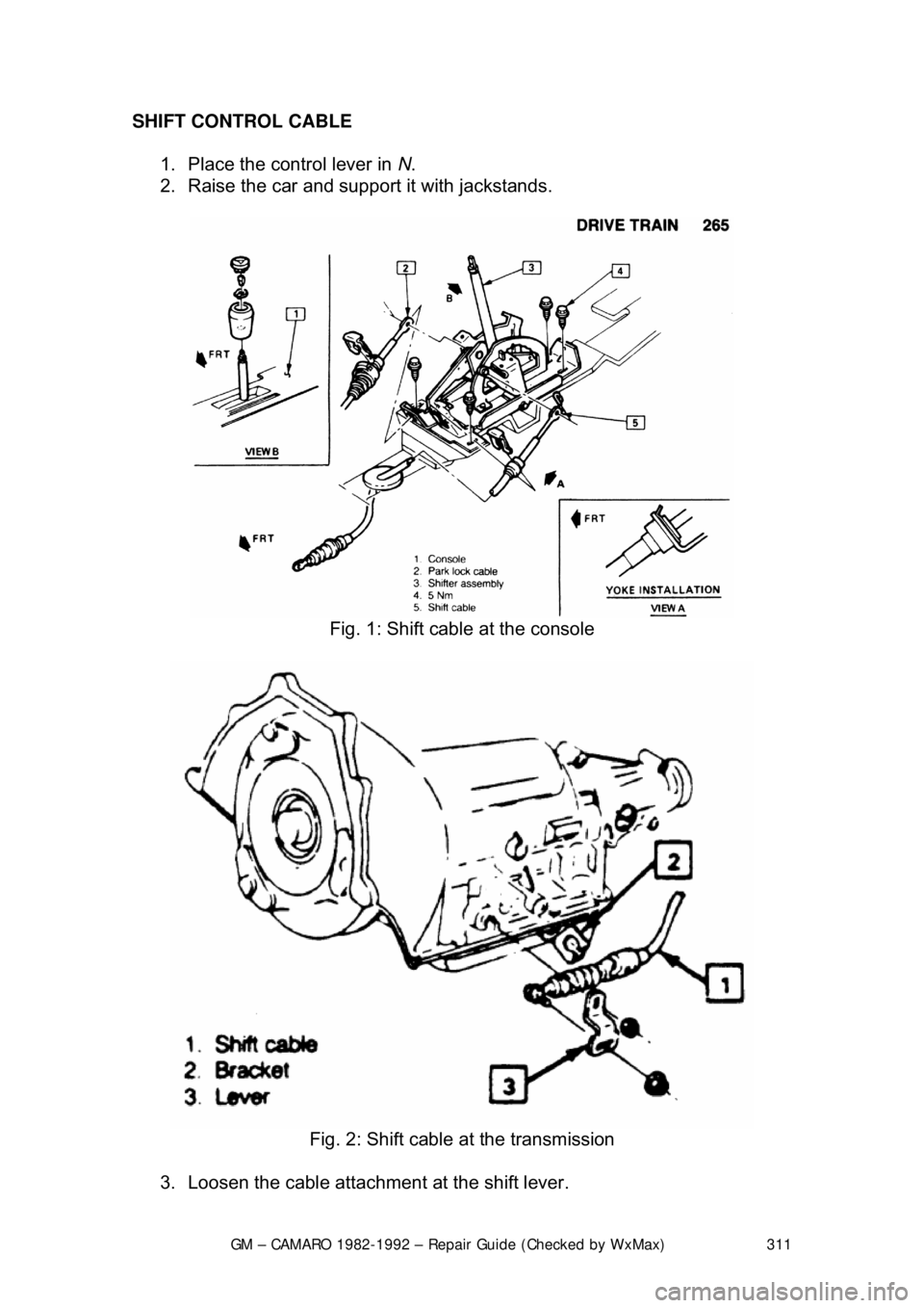
SHIFT CONTROL CABLE
1. Place the control lever in N.
2. Raise the car and support it with jackstands.
Fig. 1: Shift cable at the console
Fig. 2: Shift cable at the transmission
3. Loosen the cable attachment at the shift lever.
Page 312 of 875

GM – CAMARO 1982-1992 – Repair Guide (Checked by WxMax) 312
4. Rotate the shift lever clockwis
e to the park detent and then back to
neutral.
5. Tighten cable attachment to 11 ft. lbs. (15 Nm).
The lever must be held out of P when tightening the nut.
SHIFT LINKAGE 1. Place the manual shaft of the transmission in N. Place the console shift
lever in N.
2. Install the cable in the slot of the shift lever. Adjust the cable so that the
pin has free movement.
3. Install and tighten t he nut to the pin.
THROTTLE VALVE CABLE 1. After installation of the cable to the transmission, engine bracket, and the
cable actuating lever, check to assure that the cable slider is in the zero
or fully re-adjusted position.
2. If cable slider is not in zero or fully re-adjusted, depress and hold the
metal re-adjust tab. Move the sli der back through the fitting in the
direction away from the cable actuat ing lever until the slider stops against
the fitting. Release the metal re-adjust tab.
Fig. 3: TV cable and linkage