1980 SKODA 120 LSE wheel
[x] Cancel search: wheelPage 44 of 238
2.7.-2.8
Guide Rings Regrinding of the foce of the front
cronkshoft
web results in
on increosed (oxiol) ploy
of the
shoft. Reploce therefore the originol guide
ring with
on oversize one. Oversize guide
rings ore fitted exclusively
to
the regrround loterol
foce of the cronkshoft web.
Stondord size rings
should be olwoys fitted
to
the thrust ring side (next
to the timing geor).
Thrust Ring
lf the thrust ring under the cronkshoft timing
geor (sprocket)
obutting ogoinst the guide
ring is worn to on
extent
which mokes domoge of
the guide
ring likely, reploce it
with o new one
or regrind it.
The moximum permissible
regrinding is, how-
ever, to o thickness of only 3.75 mm.
Cronkshoft Moin Beoring Shells
Fit the cronkshoft moin beorings (shells)
occording to the respective nominol diometer
of the cronkshoft
iounnols. The shells
ore not
provided with o diometer symbol so thot they
hove to be checked for
the respective woll
thickness with o micrometer.
2.8 FLYWHEEL WITH GEAR RING
Boloncing -
Removol ond Refitting
A new flywheel ossembly is o
stoticolly bo-
lonced unit, its moximum permissible residuol
out-of-bolonce weight being '10
gcm. The finol
lf one of the
shells
is worn or domoged, o ll
cronkshoft moin beoring shells must be reploced without foil !
For the respective correlotion of the cronk-
pins ond connecting rod
big-end beorings see
Chopter 2.11. dynomi<
ism shr
sembfed
Thus
sitioq of
shoft be
from o
1
When
rnork on
zero line
ond prol
mork op
cylinder
the rem<
gcm sin
mosses (
concentr
cronksho
holes rot
wheel ir
interf erel
For thi
on the r
sition, i.
cronksho
fore the
When
one or wl
follows:
1. Fit .
residuol o
olly offec
2. The
bolonce r
hos o hig
correctior
once. lt
occording
porogroph
Chopter 1
bending t
To Reploc
Reploce
worn or d,
ring, toke
the interfr
sion). The
prime impr
ossembly
storter mo
The gec
removed b
port pod
cr
MP 1-153. I
ing the ge
it off. The
monufoctut
When ur
front foce
ond drill
o
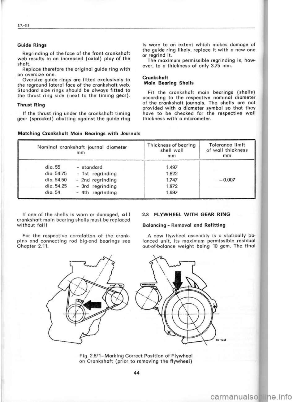
Fig.2.8l1- Morking
Correct Position of
on Cronkshoft (prior
to removing theFlywheel
f lywheel)
Motching
Cronkshoft Main Beorings with Journols
Nominol cronkshoft mmiournol
diometer Thickness
of beoring
shell woll
mm Toleronce limit
of woll thickness
mm
dio. 55 dio.54.75
dio. 54.50 dio.54.25
dio. 54 stondord
1st regrinding
2nd regrinding
3rd regrinding
4th regrinding 1.497
1.622
1.747
1.872
1.997
-
0.007
44
Page 70 of 238
Turn
the flonge
on the centering
orbor so thot
the longer, cylindricol port
foces the clutch,
push it ogoinst the friction plote
hub, ond olign
the ends of the levers to touch the flonge.
A deviotion from the ploneness
of 0.1 mm
is
permissible. Use feeler gouges for checking
this deviotion.
lf it is not possible
to odiust the out-trovel of
the clutch releose levers to o volue given
by the
length of the flonge cylindricol port
due to
excessive weor
of the friction plote, odiust to
the next higher volue.
Clinch nuts on the
odiusting nuts bocked off up to the end of the
threod ore o worning of o weor limit which pre-
cludes ony further odiustment
of the clutch.
4. After hoving reossembled
the engine with
o new or odiusted clutch,
check ond, if necess-
ory, odiust the cleoronce between the releose
levers ond the throw-out beoring -
see Chop-
ter 15.4.
3.3 CLUTCH DISMANTLING
Owing to its simplicity,
it is not necessory
to
describe in detoil the dismontling
of the clutch,
but some speciol feotures
deserve ottention.
1. lf the friction plote
ond clutch cover ore
intended to be re-used, mork their relotive
positions using centre punch
morks to preserve
the originol bolonce of the ossembly.
2. To dismontle
the clutch, it is
necessory to
compress the clutch cover to relieve the stress
of the releose lever bolts. For this purpose
use
the MP 2-101
ossembly plote
shown in Fig.3.4/1.
After screwing off the releose lever nuts ond
compressing the clutch cover,
the clutch is
reody for dismontling.
3.4 CLUTCH REASSEMBLY
1. Locote
the clutch pressure
plote
on the
MP 2-101
ossembly plote
ond fit springs
on the
cylindricol bosses. Before fitting
the springs, it
is odvisoble to check them for
complionce with
the volues specified
in the following Toble.
Toble of Clutch Springs
Lood
Length of spring in mm
lin -rrr"ltp1
Mounted length
31.55'10+36
(s2t3.6)
Length of compressed spring 29.5
I 580 (59) 2.
Instoll retoining plotes
on the clutch
springs ond fit the clutch cover with releose
lever springs in position.
Assemble the clutch
cover with the pressure plote,
observing the
morks indicoting their relotive positions.
When
ossembling new pot'ts,
their positions
ore of no
consequence.
3. Slip o 4.5 mm high pod
over the ossembly
plote bolts (the
plote
con be used
for Skodo
1000 MB ond Skodo 100 cors os well,
ond by
using pods
of different heights, the plote
con be
odopted for different
types of clutches), fit the
yoke of the
iig on
the plote
bolt ond compress
it by screwing down the nut till the bottom port
rests on the pod.
When compressing the clutch
cover toke core thot the projections
of the
pressure plote
ore correctly centered in
the
cover slots to prevent
o distortion of the clutch
cover.
4. Slip the bottom ends of the releose levers
under the springs instolled in the cover ond fit
them with their longitudinol
slots on the sup-
ports. Slip odiusting woshers on the bolts of the
pressure plote ond screw down the nuts with
their cylindricol port
focing the woshers. Then
odjust the height of the releose levers with
these nuts so thot their ends touch the shoulder
of the yoke
bottom port.
The difference of the
lever height should not exceed 0.'l mm. This
odiustment olso sets the recommended
distonce
of the levers from the pressure
plote
beoring
surfoce.
Use clinch nuts for locking the odiusting nuts
in position,
put
supporting clips under the re-
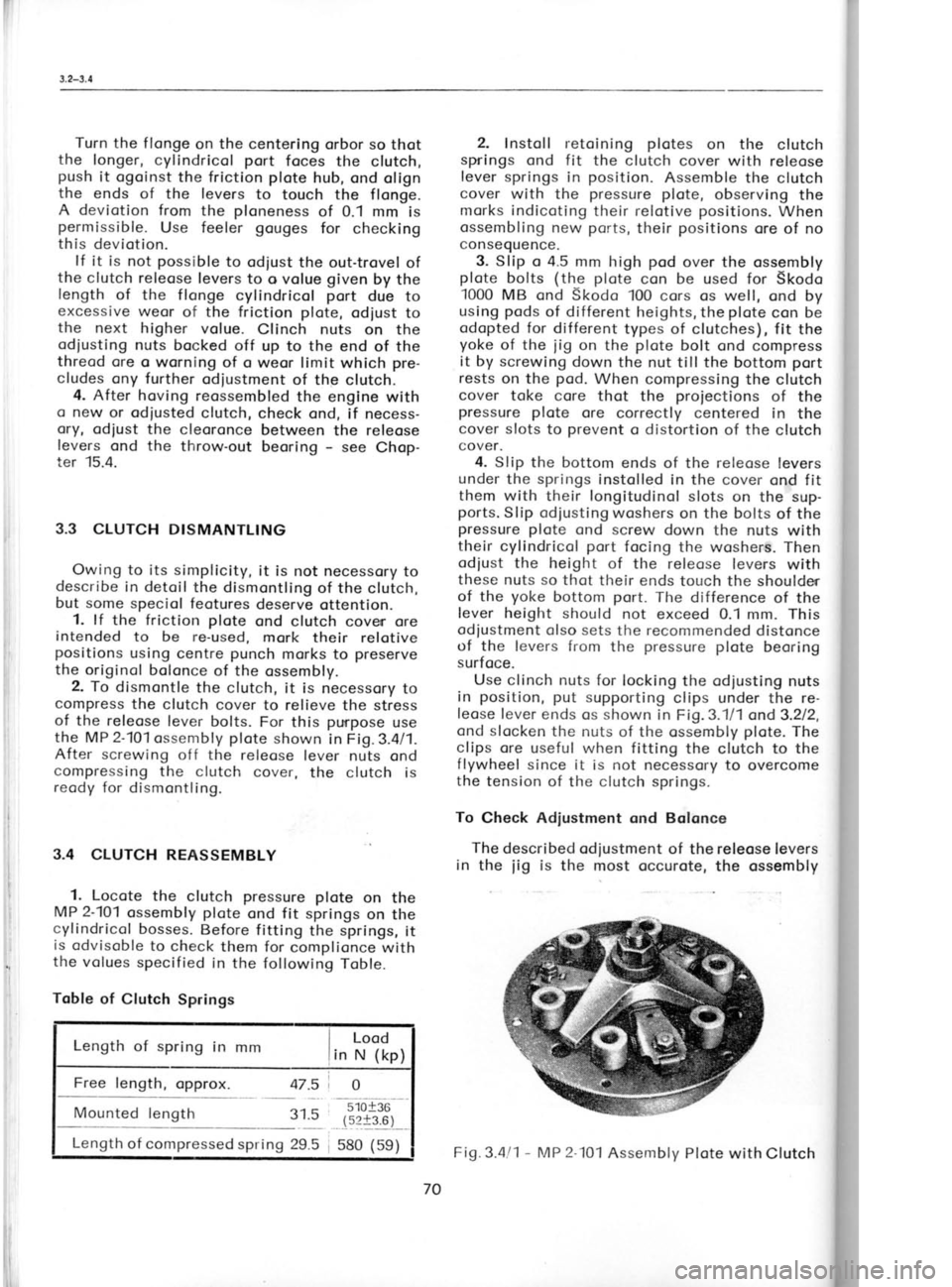
leose f ever ends os shown in Fig.3.111 ond3.212,
ond slocken the nuts of the ossembly plote.
The
clips ore useful when fitting the clutch to the
f lywheel since it is not necessory to overcome
the tension of the clutch springs.
To Check Adiustment ond Bolance
The described od justment
of the releose levers
in the
iig is
the most occurote, the ossembly Fig.3
Dim
plote be
simulotin
For on<
porogropl
The cl
with the
friction ;
ports of '
clutch on
To bol
centering
pressure
the chips
lf thesr
boloncing ing holes
in o circk
4mmofr
between
fostening
3.5 FR|C
lf the f
it is odvi
8.5 mm th
When r
the frictio
ond only r
complicot
After hr
the plote
if necessc
recheckinl
quired.
70 Fig.3.4l1
-
IAP 2lol
Assembly Plote with Clutch
Page 80 of 238
Proceed
in the some woy with the
3rd- ond
4th-speed geors.
lf the morked position
of the neutrol is not
midwoy between the side morks (check
visu-
olly), remove the pinion,
mork the positions
of
the striking forks on
their rods (preferobly
on
either side), slocken the forks ond 'rnove
them
toword the required centre by
the distonce of
the deviotion of the neutrol morking. Then lock
the striking forks in position
with screws.
For the striking fork tightening torgue see
Chopter 1.8. 13. Adiust the reverse geor position
so thot
there is o gop
of obout 2
mm between its teeth
ond the odioining teeth, ond swing the striking
fork of the first ond second speed
to moke sure
thot it connot foul
the teeth.
14. Reinstoll the pinion
with its respective
woshers ond lock it in position.
Shift the strik-
ing fork rods to moke sure thot, for exomple,
o movement opposite to the required one of the
striking forks did not toke ploce,
i. e. thot the
neutrol is midwoy betvr'een the engogement
positions of the synchronizing clutches. Correct
ony error ond remove
ogoin the pinion.
Fitting Drive Geors ond Clutch Shqft
15. lnstoll the ossembled drive shoft into the
housing ond slip the splined bush on it.
Top home the seol ring with its seoling lip
pointing outwords into the guide
of the clutch
thrrowout sleeve, ond smeor it with oil. Then
threod the clutch shoft through the ring to
instoll it into the splined bush ond put
it into
the housing together with the guide provided
with o cooting of seoling compound on its cyl-
indricol bedding surfoce. Secure both the shoft
ond the sleeve with circlips.
lnstoll the sleeve guide
with its droin hole
level with the porting plone
of the housing ond
focing the pinion.
For the speciol seoling compound see the
note in Chopter 10.1.
16. Put the pinion
with geors
into the housing
ond oil oll synchronizing rings. Fit the MP 5-104
iig for
setting the crown wheel bocklosh into
the bore of the differentiol beoning ond the
fitted cover, fit the ossembled differentiol in it,
ond close the housing with the other housing
holf ofter hoving cooted the seoling surfoces
with o seoling compound.
Fit o rubber ring in the recess of the boss
beside the stud
bolt ond put
o spring wosher
under the nut. Tighten the remoining nuts
without ony woshers (the
stress of the bolts
ofter the tightening of the nuts provides
for'
their suff icient securing). Tighten the nuts
moderotely for the time being.
For the speciol seoling
compound refer to the
note in Chooter 10.'1. 17.
Proceeding through
the bore of the differ-
entiol beoring in the upper holf of the housing,
fit another
iig, the MP
5-104,
on to the differen-
tiol with flonges clomped so os to fit
into the
topered roller beoring cover, locote the cover
pocking, ond fosten
the cover by meons
of three
nuts. lf the clomping or drowing close of the
flonges of this jig
proves inodequote, it is
necessory to drow close the flonges olso of
the
first, previously
inserted
iig.
18. Drive the guide
of the clutch throwout
sleeve into the housing using the MP 3-103 drift,
top home the drive shoft, ond insert
two od-
iusting woshers under the collor of the
pinion
shoft boll beoring on both holves of the housing
ofter hoving determined their thickness by
meosuring. Using o wire needle
inserted into
the holes of
the tobs of the woshers orronge the woshers so
thot they do not overlop the porting plone
of
the housing,
then instoll the cover ond spring
woshers, ond tighten the nuts (seeChopter
1.8).
19. Fosten the housing by tightening the nuts
(see Chopter 1.8) ond lock in position
the guide
of the clutch throwout sleeve with the respect-
ive clip using the spring wosher under the
clip
nuts.
4.3 ASSEMBLING
FINAL DRIVE
Ref itting Differentiol 20. Turn the housing into the horizontol pos-
ition. Rotote the ends of the knurled hondles
of the inserted iigs MP 5-104
to move the re-
instolled differentiol (see previous porogrophs
16 ond 17) until the crown wheel withdrows
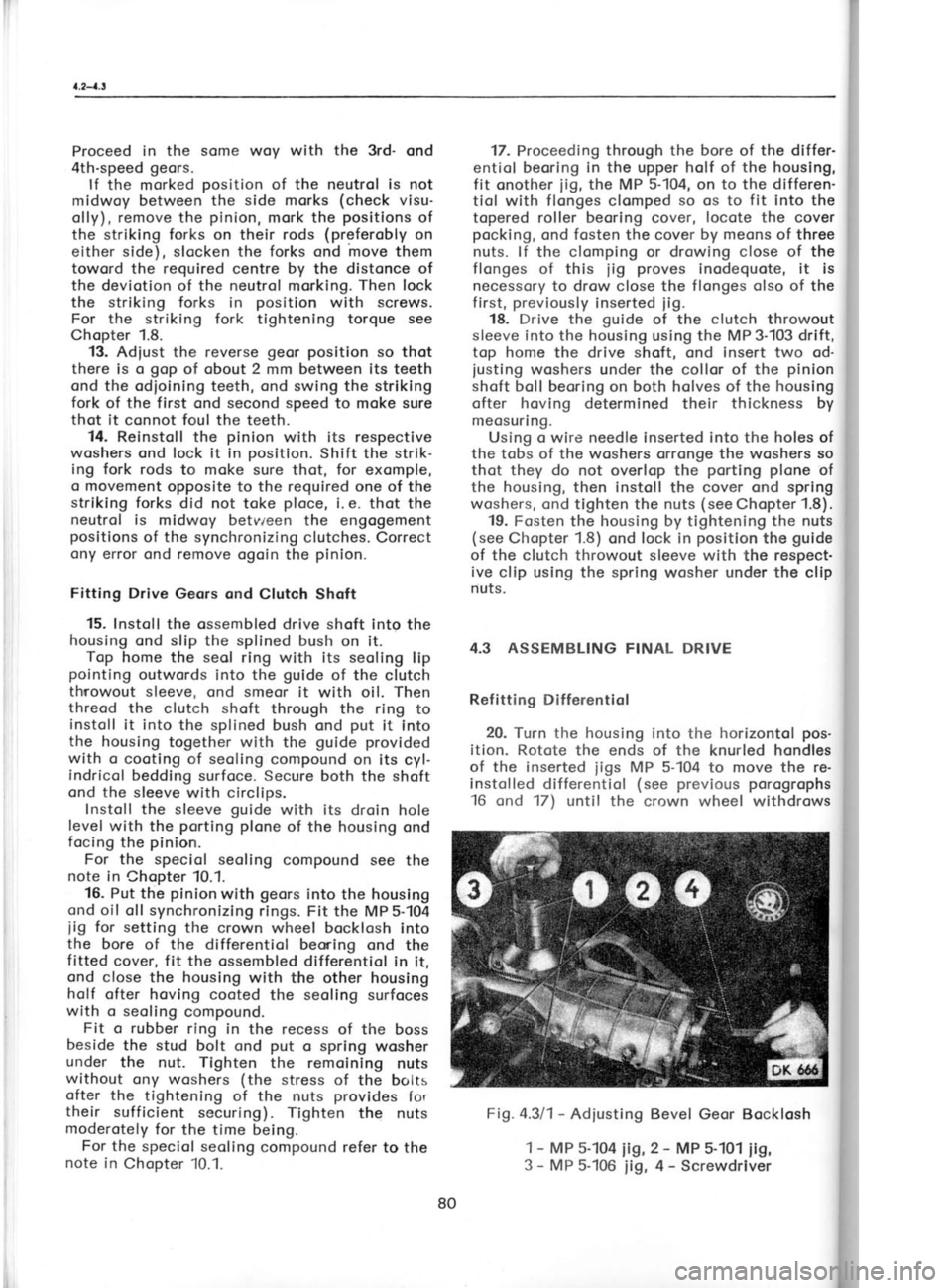
Fig. 4.311- Adiusting
1 -
MP 5-104 iig,
3 -
MP 5-106
iig,Bevel
Geor Bocklosh
2 -
MP 5-101
iig,
4 -
Screwdriver from
the
Determir
swivellin
To rotr
iig with
tiol stor
21. Ins
on the b,
rotote th
the diol
ible to th
Retoin
ogoinst 1
cover. Tl'
teeth chc
losh on t
of the ho
wheel sic
fied volut
the hond
fully its c
( preferob
wheel). I
opened f1
respectivr
of the
iigr
Now tl"
iusted on
flonges o'
topered r
This situc
trot i o n.
Fig. a3fi
for tc
1
22. Rem
side (turn
withdrow
dimension hos to be
roller beori
Measuring 23. Unscr
the toperer
locote it o
q,
ry
80
Page 82 of 238
4.3-4.4
F
I
t
F
i
!
I
r
{.3-4.4
6. Remo
b) Crownwl Tools:
Settin
not le
1. Install
one of the
Glave Cylir
that the p
pendicular
2. Lock
between tl"
cover. 3. Using
back and
clearance I
teeth. This gauge, anc
wheel(see legible the
O.18mm bi
4. lnsuffi
wheel is tc
increase tl
from the nc
the equiva
This will p
increase th
Excess c
thickness
Selector Si
To worl
shims to n
(a) Bac
(b) Act
Refitting C Assembly
29. Instc
ond the rel it with nutr
-looded brc
To
(a) O.3i
(b) o.2r
lf
the shims
connot be set up exoctly to the
colculoted thickness, determine o thickness
which would result
in o prelood
due to on
overoll increose of 0.03 to 0.07 mnr of the di-
rnension of the shims.
27. Ploce the topered roller beoring on the
respective bore, bolt the other MP 5-107
iig on
the housing ond rotote
the centre bolt to press
the beoring into the housing os for os it will go.
Remove the iig, fit the shrunk-on
ring on the
stor pinion,
and lock the ring in position
using
o circlip. Lubricote the beoring with oil, f it the
respective shims on the beoring ond the gosket
on the cover, ond bolt down the cover.
Turn over the housing ond press-in
the other
beoring in the some monner (the press-fitting
iig is olreody in
position),
instoll the preporred
shims, ond bolt down the cover with its gosket.
28. Meosure how deep is tlre drive shoft
beoring below the level of tlre housing
surfoce
ond compensote the difference
with shims up
to o moximum protrrrsion
of 0. I mm -F0.05
rnnr.
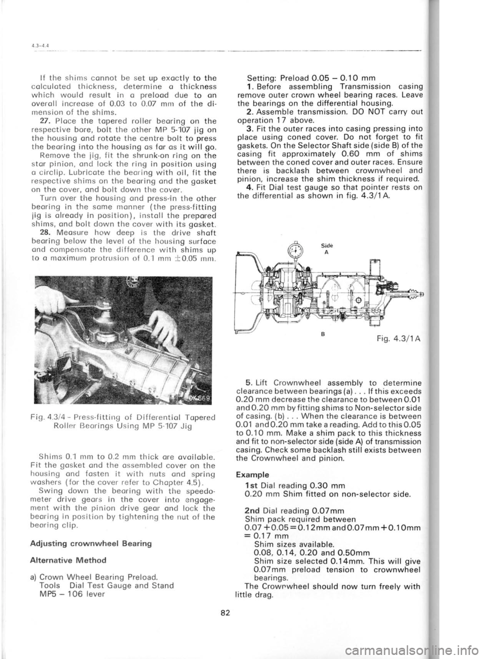
Fig.4.3/4 -
Press-f itting of Differentiol Toperecl
Rollr:r Beorings
Using MP 5-107 Jig
Shims 0.1 nrm to 0.2 mm thick ore ovoiloble.
Fit the gosket
ond the ossembled cover on the
housing ond fosten it with nuts ond spring
woshers (for the cover refer
to Chopter 4.5).
Swing down the beoring
with the speedo-
meter drive geors
in the cover into engoge-
nrerrt with the pinion
drive geor
ond lock the
beoring in position
by tightening the nut of the
beoring clip.
Adjusting crownwheel Bearing
Alternative Method a) Crown Wheel Bearing Preload.
Tools Dial Test Gauge and Stand
MPs -
1OG lever Setting:
Preload O.Ob -
O.10 mm
1. Before assembling Transmission casing
remove outer crown wheel bearing races. Leave
the bearings on the
differential housing.
2. Assemble transmission. DO NOT carry out
operation 17
above.
3. Fit the outer races into casing pressing
into
place using coned cover. Do not forget to fit
gaskets. On the Selector Shaft side (side
B) of the
casing fit
approximately O.60 mm of shims
between the coned cover and outer races. Ensure
there is
backlash between crownwheel and
pinion, increase the
shim thickness if required.
4. Fit Dial test gauge
so that pointer
rests on
the differential as shown in fig. 4.3/1A.
5. Lift Crownwheel assembly to determine
clearance between bearings (a).
. . lf this exceeds
O.2O mm decrease the clearance to between O.O1
and 0.20 mm by f itting
shims to Non-selector side
of casing. (b)
. . . When the clearance is between
0.01 and0.20 mm take
a reading. Addtothis0.OS
to 0.10 mm. Make a shim pack
to this thickness
and fit to non-selector side (side
A) of transmission
casing. Check some
backlash still exists between
the Crownwheel and pinion.
Example 1st Dial reading 0.3O mm
0.20 mm
Shim fitted
on non-selector side.
2nd Dial reading 0.07mm
Shim pack
required between
0.07 +O.O5 =O.12mm
and0.O7mm *O.1Omm
= 0.17 mm
Shim sizes available.
0.08, O.14, O.2O and O.SOmm
Shim size selected O.14mm. This
will give
O.07mm preload
tension to crownwheel
beari ngs.
The Crownwheel should now
turn freely with
little drag. Fis.
4.3/1A
82
Page 84 of 238

Remove the clip of
the
clutch throwout beor-
ing guide,
insert the MP 3-102
iig into
the guide,
open its iows, ond withdrow the
guide.
After
hcving renewed the seol ring, drive home the
guide using the MP 3-103 drift. The droin hole
in the guide
must foce
downword.
The lotest desing of the extrocting
iig hos
the type dcsiqnotion MP 3-112. Screw the
iig
bolt into
the
iig nut
inserted into the mech-
onism through the hole cleored by the removol
of the clutch releose cylinder. Jerk the
iig to
drive the guide
out of the housing.
Dismontling the Power Pock
For complete dismontling of the power pock,
remove it from the cor -
see Chopter 4.-1,
"Rernovol of Power Pock from the Cor". Then
proceed os follows:
1. Remove the front cover ond the cover of
the pinion boll beoring, the clutch releose
mechonism, ond the clip of the guide
of the
clutch throwout sleeve, i. e., oll component
ports ottoched
to both holves of the housing.
2. Remove the connecting bolts of the flon-
ges. Force oport the f longes using o screwdriverr
inserted into the chombers of the flonge feet
(lugs). Lifting owoy oll component ports
one
by one is the usuol procedure
of dismontling.
Toking oport of lorger units (pinion,
etc.) is
described individuolly
in the following
chopters.
3. Press out the beoring cups which hove
remoined in the housing ofter its holves hove
been seporoted.
Use the MP 5-107
iig supported
by the MP 5-108
iig.
Fig.4.al2 -
Pressing Out the Cup of the Topered
Roller Beoring
Using MP 5-107 ond MP 5-108
Jigs
4.5 FRONT COVER
The front cover ossembly forms
o self-con-
toined unit fitted to the georbox.
For both the
reossembly ond dismontling ploce
it on o work
bench. Assembling
Front Cover
1. Slip the rubber seol ring on the speedo-
meter beoring ossembly (beoring
with geors)
ond push
corefully the beoring, preferobly
by
o steody rotory motion, into the cover
iust for
enough to be oble to instoll the key
without
domoging the seol ring by the shorp edge of
the keywoy. For the some reoson, chomfer the edge of the
beoring bore before
instolling the beoring in
o new cover.
2. Lock the beoring in the oxiol direction by
instolling the key
ond spring woshers, ond by
screwing down the nut.
Slip the clip on
the
protruding pcrt of the beoring ond lock it olso
in the oxiol direction with o bolt, spring
wosher,
ond nut. Do not
tighten the nuts fully.
3. Instoll the oiled geor
chonge lever in the
cover while pushing
it only os for os the groove
for the seol
ring.With the lever in this position,
insent the seol ring
in its groove
ond push
forther the lever through the ring. Slip the
dust
boot on the lever ond ottoch it to the cover
with o length
of locking wire.
4. Attoch the fostening (mounting)
lugs using
copscrews ond spring woshers. There
is o right-
-hond ond o left-hond lug, ond their slots must
be turned owov from the cover.
FK 1t't4
Fig.4.5l1- Front
Cove'r Assembly
Dismontling Front Cover
Lift owoy the speedometer
beoring ofter
hoving removed the sleeve
clomping bolt ond
the key (held
down by the nut). Then
withdrow
the geor
chonge lever by simply pulling
it out.
4.6 PINION WITH GEARS The pinion
with geors
forms o self-contoined
unit to be instolled in the georbox.
Use o work
bench ond o press
fon both its ossembly onddismor
wheel sure t
Only c
wheel
m itted
drive.
4.8.
Whe
olso tl
o new
one is
Assem 1.P
the pi
the or" thrust
toworc
3-104 p
ground
the be, must t
meosul
2.S
collor I
ring ir
the grr
The rir
3.5 to I
th ickes
ond pu
speed
3.H
it the '
selecte
toword
dismor (by tol
itinp
free to
Clon
MP 3.1
Note
inner b
toining
either r
-speed
ports.
4. Tr
groovir
pinion.
friction
groover
groove!
5. On
ond fit
the nex sizes 3
84
Page 90 of 238
^l;
eil
ell
€; \l-
I
4.9-4.
r
O
Fig. I
((
,'.ffi
l|i
3. To evoluote
the doto
obtoined from
the diol
indicotor reoding ond the
doto of the geor
set,
odopt the following procedure:
The setting distonce of the gouge -
60.00 mm
- is morked on the gouge
orm; the reoding
of
the diol indicotor
hos shown
o deviotion
of e. g.
plus 66 divisions, i. e. 0.66 millimetres (plus
meons thot the tip
of the gouge is pushed
in-
word from the set zero position
ond the in-
dicotor reoding is higher;
o reverse deviotion -
minus reoding -
connot procticolly
occur). By
subtrocting this deviotion from the meosure on
the gouge, the octuol distonce between the
pinion ground foce ond the geor
cross oxis will
be obtoined,
i. e. 60.00 mm minus 0.66 mm :
59.34 mm.
The meosure on the crown
wheel indicoting
the ossembly
distonce of the pinion
is, foi
exomple, 59.60. Accordingly,
the pinion
must be
moved slightly
out of the housing
0.26 mm, i.
e.,
by the difference
of the two
meosurings (59.60
minus 59.34:0.26 mm).
4. Prepore
odiusting
sirims 0.30 mm thick to
be inserted
under the flonge
of the pinion
beor-
ing on further
ossembly of the housing.
Shims 0.14, O.2, 0.3, ond 0.5 mm thick ore
ovoiloble. lf the required
occurote outword shift-
ing of the pinion
connot be ochieved
with shims
of ony of the specif
ied thickness, combine them
to obtoin
the next higher
volue.
Note: The thickness of shims required
for the od-
iustment of the
pinion
con be olso
colculoted
in the following
woy:
o) Set the diol indicotor
of the Mp 5-103 gouge
os in porogroph
1of the preceding
texi i.6.,
with the gouge
odiusted on the meosuring
contoct, the reoding
of the diol indicoto-r
will be 1.00 mm.
b) .Swing the
tip of the diol
indicotor
ogoinst
the pinion ground foce ond push
the
iinion
by meons
of the Mp 5-102
beorinq
retoiner
into the housing
till the diol
indicitor reods
1.00 mm. pointer
ofter pushing
the pinion
into the
housing is the meosure (thickness)
of the
shims.
4.9 DIFFERENTIAL
Assembly 1. Instoll the sun geor (plonet)
without the
friction wosher, the two stor pinions
(sotellites),
ond the pilot pin
for the stor pinions
into the
left-hond holf of the differentiol cose (with
the
flonge for the crown wheel). The originol
dif-
ferentiol pinion
shoft pressed into the cose
must be reploced tempororily by the pilot
pin
to focilitote hondling. 2. Push the sun geor
from outside into
en-
gogement with the stor pinion
teeth ond
use
o depth gouge
to meosure the dimension by
which it protrudes
from the housing. Then, pro-
ceeding from inside, push
the sun geor
into the
obutment surfoce of the differentiol cose ond
meosure ogoin
by how
much lt protrudes
from
the housing. The difference of both meosure-
ments determines the gop
for the sliding ring.
The rings ore supplied
in thlcknesses of 1.8,
1.9,
2, 2.1,2.2, ond 2.3
mm. Select the ring whlch is
0.1 mm thinner thon
the colculoted dimension
of the gop.
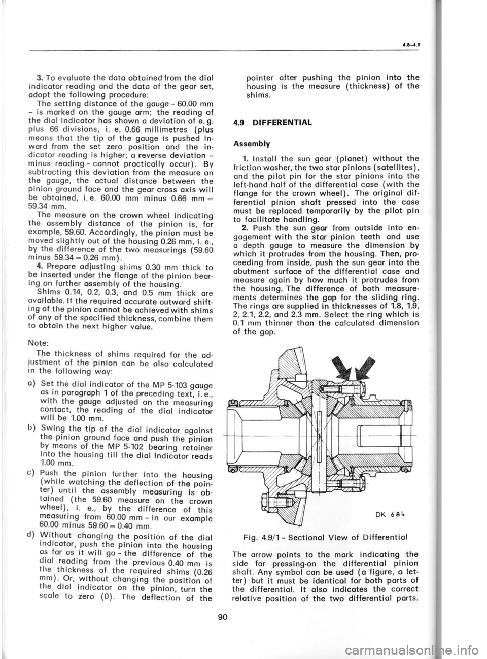
Fig. 4.9/1- Sectionol View of Differentiol
The orrow points to the mork indicoting the
side for pressing-on
the differentiol pinion
shoft. Any symbol con be used (o
figure, o let-
ter) but it must be identicol for both ports
of
the differentiol. lt olso indicotes the
correct
relotive position of the two differentiol ports.
c)
d) Push,
the pin-ion further into the housing
{while w.otching
the deflection
of the poin-.
ter) until the ossembly
meosuring
is ob-
toined (the 59.60 meosure
on th; crown
wheel) , i.
e., by the dif ference
of this
meosuring from 60.00
mm -
in our exomple
60.00 minus 59.60:0.40
mm.
Without chonging the position
of the
diol
Indicotor, push
the pinion into the housing
gs for os
it
will go -
the difference
of th6
d.iol reoding
from the previous
0.40 mm is
the thickness
of the required
shims (0.26
mm). Or, without chonging
the position
of
the diol indicotor on tfrJ pinion,
trin tf,e
scole to zero (0).
The
deilection
of the
90 Fig-
Page 95 of 238
5.
rl in
t-o o
el
st
th
w
ce
re
q
tr
t
Fig.
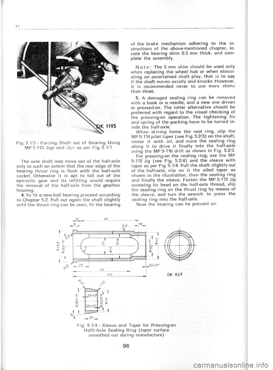
5.1i3 -
Forcing Slroft out of Beoring Using
MP 5-113 Jigs ond Jirrs os per
Fig. 5."1/1
The oxle shoft moy Inove out of the holf-oxle
only to such on extent thot the reor edge of the
beoring thrust ring is flush
with the holf-oxle
socket. Otherrwise it is opt to
foll out of the
epicyclic geor
ond its refitting would require
the removol
of the holf-oxle from
the georbox
housing. 4. To fit o new boll beoring proceed
occording
to Chopte'r 5.2.
Pull out ogoin
the shoft slightly
until the thrust ring con be seen, fit the beoring
I I
I of the
broke mechonism
odhering to the in-
structions of the obove-mentioned chopter,
lo'
cote the beoring
shim 0.3 mm thick, ond com'
plete the ossembly.
Note: The 3 mm shim should
be used only
when replocing the wheel hub or when elimirr-
oting on oscertoined shoft ploy,
thot is
to soy
if the shoft moves oxiolly ond
knocks. However,
it is recommended never
to use more shims
thon three.
5. A domoged seoling
ring con be removed
with o hook or o needle, ond o new one driven
or pressed-on.
The lotter olternotive should be
preferred with regord to the visuol checking of
the pressing-on operotion. The
tightening fin
ond spring of the pocking
hove to be
tunned in-
side the holf-oxle.
When driving home the seol
ring, slip the
MP 5-114 pilot toper (see
Fig.5.213) on the
shoft,
smeor it with oil, ond move the seoling
ring
olong it to drive it finolly into the holf-oxle
using tlre MP 5-116 drift os shown in Fig-
5-212.
For pressing-on
the seoling ring, use the MP
5-112 iig (see
Fig. 5.214)
ond the, sleeve
with
toper os per
Fig.5.-1l4. Pull the shoft
slightly out
of'the holf-oxle, slip
on it the oiled toper os
shown in the illustrotion, then the
seoling ring
ond finolly the sleeve. Fosten the MP 5-112
iig
screwing its heod on
the holf-oxle threod, slip-
the seoling ring on
the thrust ring
by meons of
the sleeve, ond turn the wrench to
press
the
seoling ring into the holf-oxle.
Now the beoring con
be pressed ott.
l^5
oi ro --
€D
.90 DK 827
4 '%
I i5
t"'
I
-l
b
F)
g
d
e \
r
e
.l I
€['----
Fig. 5.1i4 -
Sleeve ond Toper for Pressing'on
Holft-Axle Seoling Ring (toper
surfoce
smoothed out during monufocture)
12
90
6"44 t;)
20 96
Page 97 of 238

5.:
pr
stl
bc
5-t
bo
thr
u*,
on
dit
on arI
ioi
sPl
SW
I
gor
:
wo
bol
cyl
del
\
mo
th€ hot
WO
F
clo
POS +:
nec
wol
reo
toe
wit
T
o)
b)
Alil 1.
con
sloc
seo'
int
Fig.5.2l5
-
Pressing Boll Beoring
on Shoft
Using MP 5-112 Jig ond
lts Liner (smoller)
Fig.5.216 -
Connection of
Holf-oxles
with Rodius Arms
lorger ond one smoller, ond the forked plote),
screw down the
iig on the threod
of the shoft,
ond use
nuts to ottoch it
to the holf-oxle socketf
longe. The
iig of
the lotest design permits
its
simple fostening by engogement with
the holf-
oxle flonge (fit
the
iig ond
rotote
it to lock it
in position).
Instoll the lorger liner between the boll
beor-
irrg ond the
iig heod, ond
press
the boll
beorirrg
on the shoft by turning the iig wrench.
3. Reploce the lorger liner with the smoller
one (rest it ogoinst the
iig bolt heod), ond turn
the wrench in the opposite direction to press
the beoring into the holf-oxle socket.
Fitting Broke Mechonism ond Wheel Hub
4. Instoll the broke bocking plote
complete
with the broke
mechonism on the holf-oxle
socket, slip on the "O"
seoling ring ond the
cop with the seoling ring (with
the tightening
f in focing toword the holf-oxle), ond fosten
oll
the porrts
with bolts, spring woshers, ond
nuts.
The seoling ring should be driven or pressed
into the cop so thot the tightening lip foces the
beoring ond
iust so thot there
remoins
o gop
of
1 to 2 mm between the pocking
ond the cop
f longe.
5. lnsert the key in
the shoftwith its bevelled
end into the runout of the keywoy, smeor
the
hub neck with oil so
thot it does not
drog in
the seoling ring, ond fit the hub with the broke
drum in position.
Moke sure thot the key did
not move further olong the shoft (its
lifted end
in the keywoy would couse the hub to burst)
ond tighten
lightly the nut. Since o high
torque
is required
for finol tightening of the nut, put
off the tightening ond locking of the nut till
ofter instollotion in the cor. Then
tighten the
nut with full torque (see
Chopter 1.8),
top on
the hub to relieve
the possive
stress of the
toper, retighten to the specified torque, ond
lock the nut with o cotter pin.
Fitting Rodius Arms
6. Instoll
the spocer into the rodius
orm, fit
the knurled
woshers (with
the knurling toword
the orm)
to either side of the ellipticol holes of
the rodius
orm, ond fosten them with bolts ond
nuts not
forgetting the spring woshers. Do not
tighten the connection fully. Threod
the bolts
through the bolt holes so thot their nuts foce
into the cor ofter fitting the rodius orm to the
holf-oxle.
Fit the rodius
arm on the protruding
holf-oxle
pin ond threod
the bolt through the hole
of the
secrt. Slip
spocing tubes on the bolt ond pin
together with sheet shims with rubber liners
ond fosten
lightly (without tightening)
the
rodius orm to the holf-oxle using nuts
ond lock
woshers. Tighten
fully the connection
ofter fit-
ting the ossembly
in the cor when odiusting
the
reor wheel
olignment (geometry).
il
i
ii
I
I
I
I
lr
il
H, DK
?EI
98