1980 SKODA 120 LSE wheel
[x] Cancel search: wheelPage 119 of 238
\''
I
t- rL:
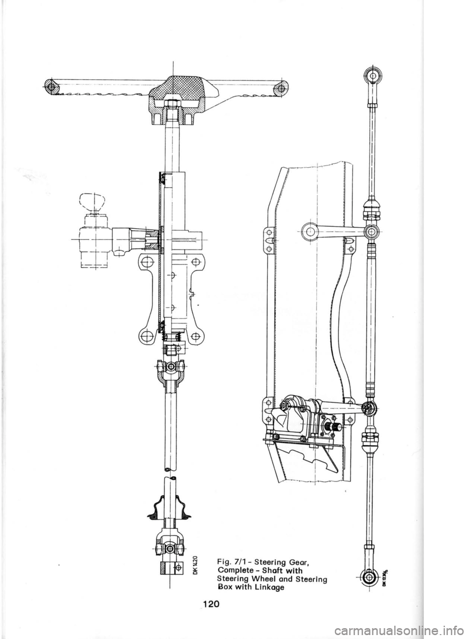
Flg. 711 -
Steertng Geor,
Complete -
Shoft wtth
Steerlng Wheel ond Stcerlng
Box wlth Llnkoge
120
Page 123 of 238
7
.7-1.8
(
t
t
t
; (
(
b
tl
ir
tl
p il
o
tl
p
odiust,
if necessory, the driving dog of the di-
rection indicotor switch -
see Chopter 13.17.
Refit the steering wheel so thot its spokes
ore horizontol, lock it in position
with the nut
(for tightening torque, see
Chopter 1.8), ond
bolt down the spoke shroud.
7.8 STEERING WHEEL SHAFT AND SHAFT
BEARING
The steering wheel (column) shoft is built
up
of two ports
with the beoring in the uPPer port.
Usuolly, it is not necessory to disconnect the
two ports
of the shoft or to remove the beoring
ond steering lock. lt
con be removed from the
cor os o unit.
Removol 1. Remove the steering wheel -
see Chop-
ter 7.7. 2. Remove the screws on the lower port
of
the shoft cowling ond pull
the cowling off.After
removing two bolts, detoch the cluster switch
on the shoft from the upper port
of the shoft
cowling. 3. Remove two front screws of the upper
Port
of the cowling ond remove the cowling.
4. Disconnect the leods
from the switches
ond the switch box.
5. From under the cor, remove the bolt of the
coupling connecting the steering
column shoft
to the steering box ond detoch the dust boot
from the floor. Remove the
bolts of the shoft
beoring (from
under the shoft)
ond the bolts of
the steering lock (from
the front) fostening the
shoft to the body, ond pull
out the shoft.
Ref itting To ref it the steering column shoft
in the cor,
reverse the removing procedure. While reinstol-
ling the steering wheel (Chopter
7.7), do not
forget to check the direction indicotor switch
for correct function.
Use ploin
ond spring woshers under the bolts
of the steering lock
brocket. Reinstoll the shoft
beoring using spocing tubes, rubber bushes, ond
ploin woshers, ond secure the bolt of
the coup-
ling, connecting the steering
column shoft with
the steering box, with
o self-locking nut (for
tightening torque, see
Chopter 1.8).
To Disconnect Shofts
Remove the bolt
of the cross-pin
ioint con-
nection.
Connecting of Shofts
Fit o fostening sleeve on the tube
with the
shoft, dip the ring in oil ond slip
it on to the shoft end with
its wedge-shoped port
toword
the beoring, instoll the spring
ond the
ioint
socket of
the shoft bottom port.
Tighten
the
connection with the bolt with self-locking
nut
(tightening torque os per
Chopter 1.8).
The sleeve must be f irst built up if
the shoft
is refitted for the first time. Locote
both holves
of the sleeve on the tube ond fosten
them
lightly together by bending the tob of one holf
of ttre sleeve over the
other. The
sleeve must
on no occount clomp the tube tightly.
Bottom Port of Steering
Column Shoft
The shoft is provided
with cross-pin
ioints
ond connot be dismontled (token
oport). Before
fitting the shoft dust boot, smeor
it with
oil to
focilitote its slipping over the pcrrts
of the joint.
For this purpose,
it is clso odvisoble to wrop
the joint
in o plostic
foil or to moke o sleeve
with o pilot
cone.
Top Port of Steering Column
Shoft -
Beoring
Removol 1. l-ift owoy the fostening sleeve
ond check
whether the shoft rototes
freely in the tube. lf
it is not the cose, unlock the steering lock ond
press out the shoft proceedirrg
from the side
of its splined
end.
2. lf necessory, remove
the circlip of the shoft
ond lift owoy the beoring. The other beoring
hos to be driven out by topping it corefully
through the cut-outs in
the tube to ovoid domog-
ing it. 3. Remove the brocket with the steering
lock
- see Chopter 7.9.
Ref itting
1. Slip tlre beoring pocked
with greose
on to
the upper port
of the shoft, then the ring with
its wedge-shoped port
focing the beoring, ond
lock both ports
in position
with the circlip.
Press the shoft into the tube ond press-in
the
beoring (ogoin pocked
with greose)
from the
other end.
2. lnstoll the brocket with the steering lock -
see Chopter 7.9.
Shoft Beorings They hove to be thoroughly lubricoted
first,
since ofter their reossembly with the shoft od-
ditionol lubricotion is not possible.
lf there is
ony doubt concerning the greose
pocking,
re-
move the circlip f
rom the inner port
of the
beoring, toke the beoring oport, cleon it, ond
reossemble it ofter hoving pocked
it with the
recommended greose,
i. e., brond NH2 of Cze-
choslovok provenience
or one of the bronds
specif ied in Chopter 7.5, porogroph
3.
124
Page 127 of 238
Shr
C
cle,
the
1
fittr
bor
(Im(
2
wit
woI
pisl
wor
the loc<(11,
3.
obo (M(
I nst
rod
the
oil' into
4.
witt
Con
prot
Inod
On f(
Inodr
oll c(
Excer
on c(
8.3 SHOCK ABSORBERS
The shock obsorbers ore of
the hydroulic,
telescopic, double-octing type of the PAL
moke.
The domping effect depends on the speed
of the
relotive movements of the oxle ond body. Doto
required for testing ond odiusting the shock
obsorbers ore given
in the following Tobles.
Front Shock Absorber -
see Fig.8.3/1
type PT 26x110,
Ser. No.443.621-215.000
1977-74 1 978 on
Maximum stroks llO mm 110 mm
Damping torce during
down stroke (compr€s-
sion 470N
500N
Damping force
during
upward stroke (expan-
sion) loSN
1
300N
Filling capacity lOO cc1OO
cc
Reor Shock Absorber
type T 26x175; Ser. No. 443.621.247.OO1
1977-78 1 978 on Both
types of shock obsorbers ore of similor
design, only their bottom fostening
is different
(the front shock obsorber hos o fostening eye,
the reor shock obsorber hos
o bolt ond locks
the outer protective
tube). They hove
o differ-
ent stroke, domping force, ond filling
copocity.
Removing ond Refitting When removing or refitting o shock
obsorber,
retoin the piston
rod (upper
fostening) by hold-
ing the flottened end of the threod in o sponner.
In the cose of
the reor shock cbsorber, retoin
the piston
rod in the bottom port
by holding the
heod of the bolt connecting it to the shock
obsorber cylinder.
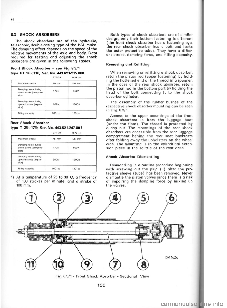
The ossembly of the rubber bushes of the
respective shock obsorber mounting
con be seen
in Fig.8.3/1.
Access to the upper mountings of 'the
front
shock obsorbers is from the luggoge boot
(under the floor). The
threod is protected
by
o cop nut. The
mountings of
the reor shock
obsorbers ore occessible from the reor luggoge
comportment behing the reor seot bockrests ofter folding owoy the upholstery on the wheel
orch. The mounting is in the cyllndricol exten-
sion piece
in the scuttle
of the reor dosh.
Shock Absorbor Dismcntling
Dismontling is o routine procedure
beginning
with screwing out the plug
(1)
ofter the pro-
tective sleeve (tube)
hos been removed. Never
dismontle the piston
volves since there is o risk
of impoiring the domping force
by mixlng up
the volves.
o
o
*)
At o
temperoture ol 25
to 30oC,
of 100 strokes per
minute, ond
100 mm. frequency
stroke of
Fig.8.3/1 -
Front Shock Absorber -
Sectionol View
Maximum stroke
175 mm
175 mm
Damping force during
down stroke (compres-
ston, 470N
500N
Damping force during
upward stroke {expan-
sronl 950N
r
200N
Filling capacity 160
cc 160 cc
130
Page 133 of 238
tr
c
\
c'
pl
r€
o1.
tt pl
tt
r€
ol
w
ot
iu
ol
dt
is
ol
sl
Rr
ot
th
th
c0
c0
Broke
Shoes ond Broke Drums
When refitting
o broke shoe with o portiolly
worn lining moke sure thot it hos o thickness
sufficient to lost till the periodic
inspection
(ofter every 20,000 kilometres). The new lining
is 5 mm thick. When it is worn down to 1.5
to 'l
mm (4
to 3.5 mm when meosured
with the
shoe), the broke shoe hos to be reploced
with
o new.or
o reconditioned
shoe with glued-on
new lining. Be sure to reploce
the respective
broke shoes in both wheels to preserve
o uni-
form broking effect.
Speciol glues or cements
ond hordening ot
high temperotures
ore required when relining
the broke shoes so thot this
iob con
be done in
speciolized repoir shops
only. For informotion,
opply to the broke monufocturer -
Autobrzdy
Not. Corp., Joblonec
nod Nisou.
Broke drums are grey
cost-iron costings. Their
unequol weor
con be rectified
by mochining to
o 231 mm diometer.
No tool morks must be left
on their surfoce
which hos to be perfectly
smooth. The olignment deviotion
ond mochin-
ing toleronce should
not exceed 0.1 mm. The
moximum permissible weor is up Lo 232
mm in
diometer.
Only broke drums
with on identicol
diometer
ore permitted
to be mounted on one ond the
some oxle.
9.2 FRONT BRAKE
ASSEMBLY
Disnrontling ond Reossembly
1. Detoch
the broke fluid supply piping
from
the broke. Absolute cleonliness is o must.
Otherwise dirt ond foreign
motterwill penetrote
into the piping.
2. Renrove bolts lrolding
down the broke yoke
crnd lift owoy rlre broke
ossembly.
3. Use the MP 6-132 gouge
to set correctly
the broke (new
or repoired)
on reinstollotion.
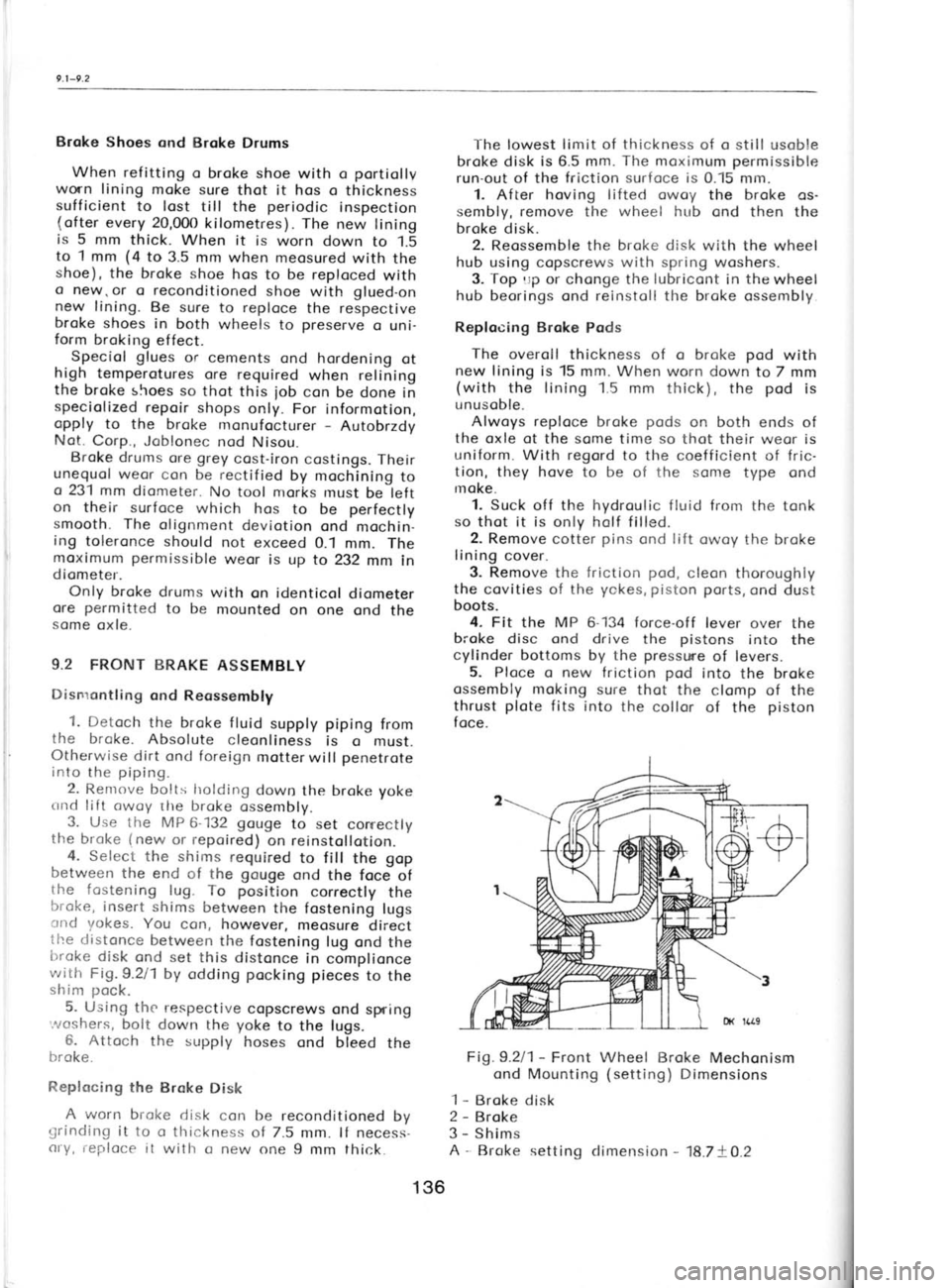
4. Select the shims required
to fill the gop
between the end of the gouge
ond the foce of
the fostening lug.To position
correctly the
broke, insert shims
between the fostening lugs
cnd yokes. You con, however,
meosure direct
the distonce
between the fostening
lug ond the
trroke disk
ond set this distonce
in complionce
with Fig. 9.211 by odding pocking
pieces
to the
shim pock.
5. Using the respective
copscrews ond spring
'.^roshers, bolt down the yoke
to the lugs.
6. Attoch the supply hoses ond bleed
the
broke.
Replocing the Brake
Disk
A worn brol
grinding it to o thickness
of 7.5 mm. lf necess-
cry, reploce it with o new one 9 mm thick. The lowest
limit of thickness
of o still usoble
broke disk is 6.5 mm. The
moximum permissible
run-out of the friction surfoce is
0.15 mm.
1. After hoving lifted owoy
the broke os-
sembly, remove the wheel hub
ond then the
broke disk. 2. Reossemble the broke disk
with the wheel
hub using copscrews with spring
woshers.
3. Top
rrp or chonge the lubricont
in the
wheel
hub beorings ond reinstoll the broke ossembly
Replocing Broke Pods
The overoll thickness of o broke pod
with
new lining is 15 mm. When worn down to 7 mm
(with the lining 1.5 mm thick), the pod
is
unusoble.
Alwoys reploce
broke pods
on both ends of
the oxle of the some time so
thot their weor is
uniform. With regord to the coefficient of fric-
tion, they hove to be of the some
type ond
rnoke.
1. Suck off the hydroulic fluid from the tonk
so thot it is only holf filled.
2. Remove cotter pins
ond lift
owoy the broke
lining cover.
3. Remove the friction pod,
cleon thoroughly
the covities of the yokes, piston
ports,
ond dust
boots.
4. Fit the MP 6-134 force-off lever over the
broke disc ond drive the pistons
into the
cylinder bottoms by the presswe
of levers.
5. Ploce o new friction pod
into the broke
ossembly moking sure thot the clomp of the
thrust plote
fits into the collor of the piston
foce.
Fig.9.2l1- Front Wheel Broke Mechonism
ond Mounting (setting)
Dimensions
1 -
Broke disk
2 -
Broke
3 -
Shims
A -
Broke setting climension -
18.7+O.2
136
Page 135 of 238
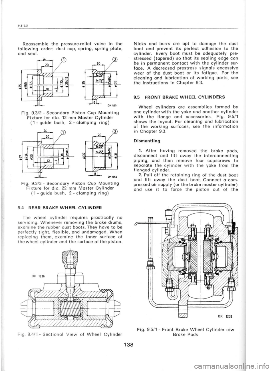
Reossemble the
pressure-relief
following order: dust cup, spring,
ond seol. Nicks ond burrs
ore opt to domoge
the dust
boot ond prevent
its perfect
odhesion to the
cylinder. Every boot must be odequotely pre-
stressed (topered)
so thot its seoling edge con
be in permonent
contoct with the cylinder sur-
foce. A decreosed prestress
signols excessive
weor of the dust boot or its fotigue. For the
cleoning ond lubricotion of working ports,
see
the instructions in
Chopter 9.3.
9.5 FRONT BRAKE WHEEL CYLINDERS
Wheel cylinders ore ossemblies formed
by
one cylinderwith the yoke
ond onother cylinder
with the f longe ond occessories. Fig. 9.5/1
shows the loyout. For cieoning ond lubricotion
of the working surfoces, see the informotion
in Chopter 9.3.
Dismontling
1. After hoving removed the broke pods,
disconnect ond lift owoy the interconnecting
piping, cnd then remove f our copscrews to
seporote the cylinder with the yoke
from the
flonged cylinder.
2. Pull off the retoining
ring of the dust boot
ond lift owoy the dust boot.
Connect o com-
pressed oir supply (or
the broke moster cylinder)
ond use it to force the piston
out of the
Fig. 9.5/1 -
Front Broke Wheel Cylinder c/w
Broke Pods
volve in the
spring plote,
Fig. 9.312 -
Secondory Piston Cup Mounting
Fixture for dio. 12 mm
Moster Cylinder
(1 -
guide bush, 2 -
clomping ring)
Fig. 9.3/3 -
Secondory Piston Cup Mounting
Fixture for dio. 22
mm Moster Cylinder
(1- guide
bush, 2 -
clomping ring)
9.4 REAR BRAKE WHEEL
CYLINDER
'l-he wheel cylinder requires procticolly
no
servicing. Whenever removing
the broke drums,
exomine the rubber dust boots.They hove
to be
perfectly tight, flexible,
ond undomoged. When
replocing them, exomine the inner surfoce of
the wheel cylinder ond the surfoce
of the piston.
Fig. 9.4/1 -
Sectionol View of Wheel
Cylinder
138
Page 137 of 238
I
I
T
!
(
(
t I
t
t
t I
'l
(
r
o cc
fold
ot the moment of
the opplicotion of the
brokes, ond led
through o rubber hose (tube)
to
the booster.
Removol ond Refitting
The broke booster is held down on the pedol
brocket by nuts ond spring
woshers. The lug of
the control volve press
button connects it with
the broke pedol,
on which it is secured by o re-
toining ring. These
mounting ports
or the con-
nections of the vocuum supply
ore to be hondl-
ed only when removing
or refitting the broke
booster.
However, we odvise you
to hove this
iob done
in o speciolized
repoir shop properly
instructed
by the broke
monufocturer. All rubber ports (in
the terms of current mointenonce,
this is
procticolly the seol of the press
button control-
ling the moster cylinder)
must be protected
from the effects of the broke fluid or other
lubriconts. Use petrol
for cleoning the rubben
ports.
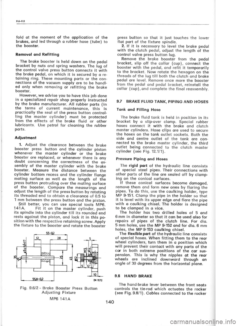
Adiustment 1. Adiust the cleononce
between the broke
booster press
button ond the cylinder piston
whenever the moster
cylinder or the'broke
booster ore reploced,
or whenever there is ony
doubt concerning
the correctness
of the os-
sembly of the moster cylinder
with the broke
booster. Meosure the distonce between the
cylinder bottom recess
ond the cylinder flonge
nroting surfoce os well os the length of the
press button protruding
over the moting surfoce
of the booster.
Compore the meosurings
ond
odiust the length of the press
button by rototing
its threoded
end to obtoin o cleoronce of 0.5 to
1 mm between the press
button ond the piston.
Still better, you
can use special
tools Mp6.
'14'lA.
Fit it on the
moster cylinder, push
its spindle into the cylinder till its rounded
end
rests ogoinst
the piston,
ond lock it in this po-
sitio-n with the respective
retoining screw.
Apply
the fixture to the booster
ond rotote the boostei press
button so thot it
iust touches the
lower
flot port
of the fixture spindle.
2. lf it is necessory
to level
the broke pedol
with the clutch pedol,
odiust the length
of the
contnol volve press
button lug.
Remove the broke
booster from the pedol
brocket, slip off the collor (cup),
connect the
booster with the pedol,
ond refit it tempororily
to the brocket.
Now rotote the hexogon on the
threods of the lug till both the clutch ond broke
pedol ore level. Remove once more the booster
from the pedol
ond pedol
brocket, neinstoll the
collor (cup),
ond complete the f inol reossembly.
9.7 BRAKE FLUID TANK, PIPING AND HOSES
Tonk ond Filling Hose
The broke fluid tonk is held in position
in its
brocket by o slip-over
clomp. Speciol rubber
hoses connect it with the broke ond clutch
moster cylinders.
Hose clips ore used to secure
the hoses on the tonk outlet sockets.
Both the
side ond centre outlet of the tonk ore con-
nected to the bnoke moster cylinder, the third
outlet being connected to the clutch moster
cylinder (see Fig. 12.111).
Pressure Piping ond Hoses
The rigid port
of the hydroulic line consists
of speciol steel pipes.
Their connections with
other ports of the line ore seoled off by clomp-
ing on the conicol surfoces-
lf these conicol surfoces
become domoged,
remove them ond form new ones by floring the
pipes. To do this, use the coulking holder,
type
MP 9-151. Clomp the pipe
in the holder so thot
it is level with its upper edge ond flore the pipe
with c coulking chisel. The holder is designed
to be clomped in o vice.
The holder
hos two drilled holes of 5 ond
6 mm in diometer so thot it con be used olso for
repoirs of pipes
of the clutch line. For dio.
5 mm holes, use the MP 9-152 ond for dio. 6 mm
holes, the MP 9-153 coulking chisel.
The flexiblepqrt
of the hydroulic line consists
of speciol hoses.
When fitting them to the reor
wheel cylinders, turn them in o position
which
will prevent
their contoct with ony ports
of the
cor in both extreme positions
of the cor sus-
pension. This is why the nipples ot the reor
wheels ore inclined
downword through on
ongle of 30 degrees from
the horizontol plone.
9.8 HAND BRAKE
The hond-broke
lever between the front seots
controls the tie-rod which octuotes the rocker
(see Fig.9.8/1). Cobles connected
to the rocker
Fig. 9.612
-
Broke Booster Press
Button
Adiusting Fixture
MP6 141A tx r5?2
140
Page 141 of 238
r 0.3-t0,5
Ihe permissible
out-of-bolonce must not ex-
ceed 50 grommes
on the rim rodius. Every new
tyre is provided
with o coloured dot on its side,
indicoting its lightest point.
Fit the tyre olwoys
with this dot focing
the tube volve.
ln this
position, the volve octs os on odditionol weight
compensoting the wheel overoll unbolonce to
o consideroble extent.
lf dynomic boloncing of the wheel is not
possible, bolonce the wheel stoticolly with the
greotest possible qssuroc|.
Boloncing weights
of 30, 50, 75,
ond 100 grommes
ore ovoiloble.
10.4 TUBED TYRES
For mounting,
dismounting,
ond repoirs of
conventionol tyres with inner tubes (for
por-
ticulors, see the preceding
Chopters), the usuol
procedures ore opplicoble. The permissible run-
out (untrue
running)
of the rim is the some os
for tubeless tyres (Chopter
10.5).
10.5 TUBELESS TYRES
The oir-tight seoling of these tyres requires
more core ond o different hondling thon thot of
the tyres with inner
tubes.
Preporotlon of Rirrr
13elore mounting the tyre, inspect the rim for
ony technicol defects. The points
to be checked
ore the rim shoulder ond the moting foce for
the tyre beods,
in oddition to the overoll con-
dition of the rim. lf ony defects ore found, the
rim must be reconditioned.
A sotisfoctory rim
nrust comply with the following conditions:
o) The
rim shoulder ond the tyre volve hole
must not be distorted;
there must be no
shcrp edges or protrusions
likely to domoge
the tyre beod. Minor unevennesses
con be
hornmered flot ond smoothed
with o file.
The moximum eccentric running
of the rim
side must not exceed 1.5 mm.
b) The moting surfoces
must be obsolutely
cleon (free
from stuck-on rubber, rust,
etc.).
Cleon them with emery poper
or o wire brush
ond coot them with point.
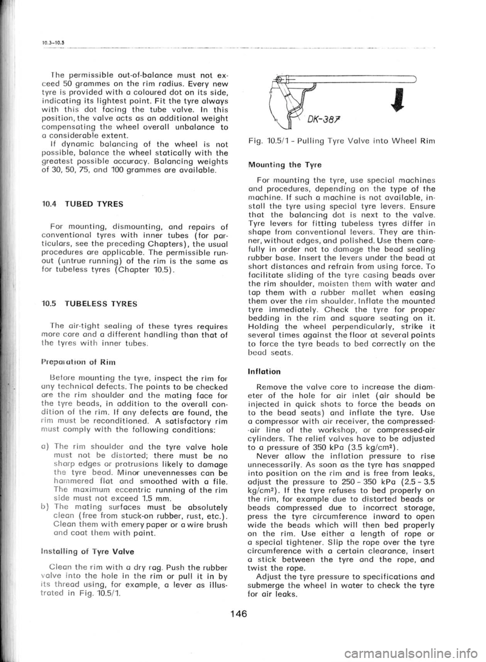
lnstolling of Tyre
Volve
Cleon the rim with o dry rog. Push
the rubber
volve into
the hole in the rim
or pull
it in
by
its threod using, for exomple,
o lever
os illus-
troted in Fig. 10.5/1. Fig. 10.5/1
-
Pulling Tyre Volve
irrto Wheel Rim
Mounting the Tyre
For mounting the tyre, use speciol mochines
ond procedures,
depending on the type of the
nrochine. lf such o mochine is not ovoiloble, in-
stoll the tyre using speciol tyre levers.
Ensure
thot the boloncing dot is next to the volve.
Tyre leverrs for fitting tubeless tyres
differ in
shope from conventionol levers. They
ore thin-
ner, without edges, ond polished.
Use them core-
fully in order not to domoge the
beod seoling
rubber bose. Insert the levers
under the beod
ot
short distonces ond refroin from using force. To
focilitote sliding of the tyre cosing beods over
the rim shoulder, moisten them with woter ond
top them with o rubber
mollet when eosing
them over the rim shoulder. Inflote
the mounted
tyre immediotely. Check the tyre for propei'
bedding in the rim ond
squore seoting
on it.
Holding the wheel perpendiculorly,
strike it
severol times ogoinst the f loor ot severol points
to force the tyre beods
to bed
correctly on the
bcad seots.
lnf lotion
Remove the volve
core to increose
the diom-
eter of the hole for oir inlet (oir
should be
iniected in quick
shots to force
the beods
on
to the beod seots) ond inflote the tyre. Use
o compressor with oir receiver, the
compressed-
.oir line of the
workshop, or
compressed-oirr
cylinders. The relief volves hove to be odiusted
to o pressure
of 350 kPo (3.5
kg/cmz).
Never ollow the inflotion pressure
to rise
unnecessorily. As soon os the tyre hos snopped
into position
on the rim
ond is free from leoks,
odiust the pressure
to 250 -
350 kPo (2.5 -
3.5
kg/cmz). lf the tyre refuses to
bed properly
on
the rim,
for exomple due to distorted beods or
beods compressed due to incorrect storoge,
press the tyre circumference inword to open
wide the beods which will then bed properly
on the rim. Use either o length of
rope or
o speciol tightener. Slip the rope over the
tyre
circumference with o certoin cleoronce, insert
o stick
between the tyre ond the rope, ond
twist the rope.
Adiust the tyre pressure
to specif
icotions ond
submerge the wheel in woter to check the
tyre
for oir leoks.
146
Page 146 of 238

11.4-11.5
I
I
I
F
r
t'
on to the coolont tonk.
Hose
clips ore formed
either by metol strips
or lengths
of wire. When
tightening the wire clips, toke core not to
domoge the rubber of the hoses.
To Fosten Pipes ond
Hoses
A correct winding of the strip is importont
to ensure o self-locking clomping of the strip
clips -
see Fig. 11.411.
Fig.11.Al1- Diogrom showing
the threoding
of
the clip strip through
the clip closp ond
the
direction of rototion of
the tightening cotter
pin -
the diogrom hos generol
opplicobility
1 -
Strip clip,2 -
Closp, 3 -
Cotter pin
The moin pipeline
routed under the cor f loor
consists of front ond reor pipes.
They ore em-
bedded in o chonnel moulded in the floor
boords ond rest on on insuloting (polysterene)
podding. From below, they ore protected
by
o guord,
the copscrews of which ore locked
in
position by spring woshers.
Use pipe
holders (yokes) to fosten the pipe-
line to the floor. In
the front
ond reor port
of
the cor, tighten
the pipes
over the insulotion
lrod ond insert
spring ond ploin
woshers under
the nuts.
Do not use insulotion pods
for bends
forming the tronsition from
the front
ond reor
lower flot ports.
Use spring woshers under
the
heods of copscrews.
Before instolling the pipes, prepore
ouxiliory
yokes (or use lengths of wires ottoched to the
provisionolly screwed-in copscrews of the pipe-
line guord) to liold the pipes
in the moulded
chonnel in
the floor before
the finol fostening
of their guord.
The woter line runs
under the cor together
with other lines, pull-rods,
etc. For their mutuol
ref otive orrongement see Chopter 12.7. Removol
To moke the underbody occessible for hond-
ling the pipes,
ploce
the cor over o floor pit
or
on o romp. The minimum required cleoronce is
obout 650 mnr.
1. Remo.re the guords
of the pipes
ond the
fuel tonk, lift owoy the spore wheel, ond loosen
the yokes
holding the pipes
to the floor.
2. Remove droin screws to droin the coolont
from the pipes -
see the illustrotion in Chop-
ter 15.'13.
3. Remove one hose clip in the middle
of the
cor to disconnect
the pipes
(ottention -
the
remoining coolont will f low out), ond dis-
ossemble the line.
4. Disconnect the pipe
ends from the hoses,
ond detoch the pipes
from the floor or other
ports of the cor.
5. Pull out the reor pipes
possing
them core-
fully oround the vorious cor ports.
6. Pull out the front pipes.
Turn
the front
wheels into their left lock position,
disconnect
the steering linkoge from the steering
reloy
lever ond the steering knuckle orm of the
right-
hond wheel, ond push
the linkoge ogoinst the
oxle body. While removing the pipes,
rotote the
left-hond pipe clockwise (when
viewing the cor
front end), ond the right-hond pipe
onticlock-
wise.
Reinstollotion Reverse the dismontling procedure
when re-
instolling the woter line. While connecting the
steering linkoge, poy
ottention to the condition
of boll pin
seoling cups (fit
new cups if the old
ore domoged). Fill in the recommended
coolont
ond bleed the cooling system.
11.5 COOLANT TEMPERATURE CONTROL
Throughf low Thermostot
This thermostot shuts off the inlet of the
coolont into the rodiotor
during the engine
heoting-up period. lt is mounted on the engine
- see Chopter 2.3, por.
30.
The thermostot operotes within the following
volues:
it begins to open ot 80+2"C
it is fully open ot 90+4oC
its lift ot full opening
11 mm
When closed, it
is permitted
to let poss
o nroximum
of 0.5 litres
of coolont per
minute,
ond it must not be closed by o bock pressure
of 0.16 MPo (1.6
kg/cm2).
When removing the thermostot by rototing
tlre rivet in the volve disk, breok owoy sedi-
I i
i 152