1976 CHEVROLET VEGA turn signal
[x] Cancel search: turn signalPage 24 of 87
Downloaded from www.Manualslib.com manuals search engine is reduced below 5 MPH.
The shift speeds chart indicates
the speeds at which each upshift of
the transmission should be
per
formed to produce the best com
promise between vehicle perform
anceand fuel economy.
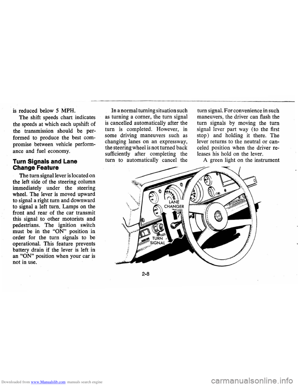
Turn Signals and Lane
Change Feature
The tum signal lever is located on
the left side of the steering column
iIllmediately under the steering
wheel. The lever
is moved upward
to signal a right turn and downward
to signal a left tum. Lamps on the
front and rear of the car transmit
this signal to other motorists and
pedestrians. The ignition switch
must be in the
"ON" position in
order for the tum signals to be
operational. This feature prevents
battery drain if the lever
is left in
an
"ON" position when your car is
not in use. In
a normal turning situation such
as turning a comer, the tum signal
is cancelled automatically after the
tum
is completed. However, in
some driving maneuvers such
as
changing lanes on an expressway,
the steering wheel
is not turned back
sufficiently after completing the
tum to automatically cancel the
2-8
tum signal. For convenience in such
maneuvers, the driver can flash the
tum signals
by moving the tum
signal lever part way (to the first
stop) and holding it there . The
lever returns
tq the neutral or can
celed position when the driver re
leases his hold on the lever.
A green light on the instrument
Page 25 of 87
Downloaded from www.Manualslib.com manuals search engine cluster flashes to indicate proper
operation of the front and rear turn
signal lamps.
If the indicator lamp
remains on and does not flash,
check for a defective lamp bulb.
If
the indicator fails to light when the
lever
is moved, check the fuse and
indicator bulb.
NOTE: For operation of hazard
flasher, see page 3-1, in
Section "In
Case of Emergency."
Horn
The horn on your car is actuated
by firmly pressing on the pad in the
center of the steering wheel.
As a good motorist,
~se of the
horn should be kept at a minimum.
However, acquaint yourself
as soon
as possible with this function of
your car, should it ever become
necessary to give a warning to a
pedestrian
or another motorist.
Power Steering
If the steering system power as
sist fails due to some malfunction,
or because the engine has stalled,
the vehicle can still be steered.
However, much greater effort
is re
quired, particularly in sharp turns.
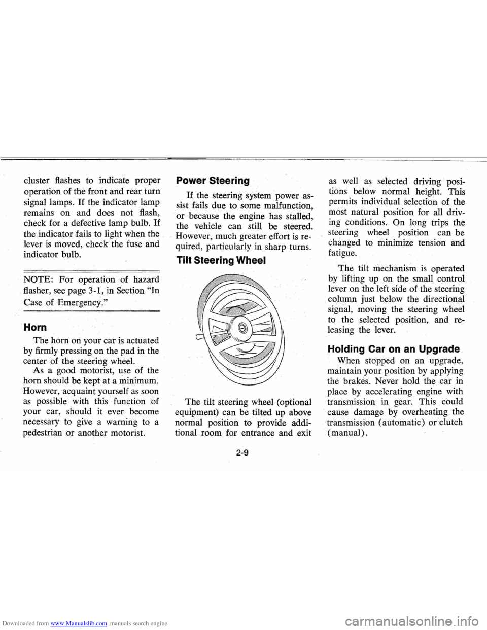
Tilt Steering Wheel
The tilt steering wheel (optional
equipment) can be tilted up above
normal position to provide addi
tional room for entrance and exit
2-9
as well as selected driving· posi
tions below normal height. This
permits individual selection of the
most natural position for
all driv
ing conditions.
On long trips the
steering wheel position can be
changed to minimize tension and
fatigue.
The tilt mechanism
is operated
by lifting up on the small control
lever on the left side of the steering
column just below the directional
signal, moving the steering wheel
to the selected position, and re
leasing the lever.
Holding Car on an Upgrade
When stopped on an upgrade,
maintain your position by applying
the brakes. Never hold the car
in
place by accelerating engine with
transmission in gear. This could
cause damage by overheating
the
. transmission (automatic) or clutch
(manual) .
Page 46 of 87
Downloaded from www.Manualslib.com manuals search engine In Case of Emergency
Four Way Hazard
Warning
Flasher
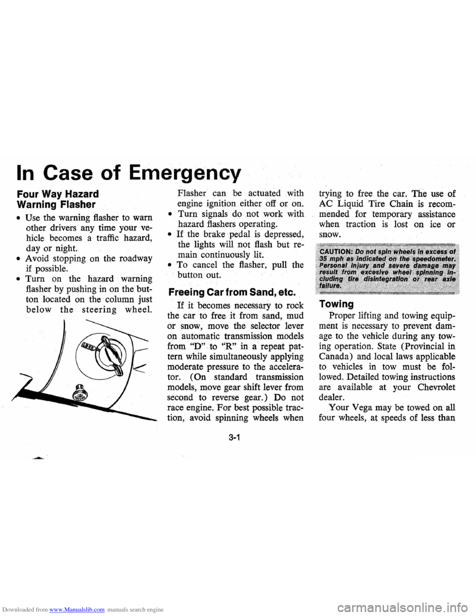
• Use the warning flasher to warn
other drivers any time your
ve
hicle becomes a traffic hazard,
day or night.
• A void stopping on the roadway
if possible.
• Turn on the hazard warning
flasher by pushing
in on the but
ton located on the column just
below the steering wheel. Flasher
can
be actuated with
engine ignition either
off or on.
• Turn signals do not work with
hazard flashers operating.
• If the brake pedal is depressed,
the lights will not flash but
re
main continuously lit.
• To cancel the flasher, pull the
button out.
Freeing Car from Sand, etc.
If it becomes necessary to rock
the car to free it from sand, mud
or snow, move the selector lever
on automatic transmission models
from
"D" to "R" in a repeat pat
tern while simultaneously applying
moderate pressure
to the accelera
tor.
(On standard transmission
models, move gear shift lever from
second to reverse gear.) Do not
race engine. For best possible trac
tion, avoid· spinning wheels when
3-1
trying to free the car. The use of
AC Liquid Tire Chain
is recom
mended for temporary assistance
when traction
is lost on ice or
snow.
Towing
Proper lifting and towing equip
ment
is necessary to prevent dam
age to the vehicle during any tow
ing operation. State (Provincial in
Canada) and local laws applicable
to vehicles in tow must be
fol
lowed. Detailed towing instructions
are available at your Chevrolet
dealer. Your Vega may be towed on
all
four wheels, at speeds of less · than
Page 83 of 87
Downloaded from www.Manualslib.com manuals search engine Air Conditioning System Compressor 011 (525 vis.) '" . • • • . . • • • . • • . . • • • . . . . . .. 11 oz.
Refrlgerant-R-12
...•••.•..........•.......... 2 lb. 13 oz.
Turbo Hydra-matlc ., ......•.....••.
3-speed Transmission •..•....•••.••
4-speed Transmission ............ .
5-speed Transmission
............ .
U.S. Measure
10.0 qts.
3.0 pts.
3.0 pts.
3.0 pts.
Imperial Measure
8.25 qts.
2.5 pis.
2.5 pis.
2.5 pts.
ITEM
Engine Oil Filter
Radiator
Cap
Gasoline Cap
Air Cleaner (1 bbl.)
(2 bbl.)
Carburetor
Fuel Filter
Positive Crankcase Valve
6-2
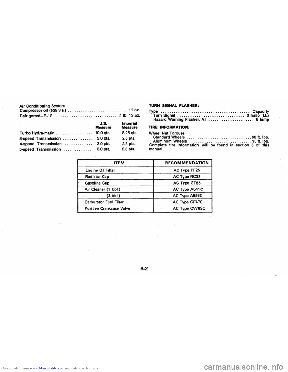
TURN SIGNAL FLASHER:
Type
..•.•.••.•••••••.•••.••.•••••...••••.•.• . Capacity
Turn Signal ..•.•.••.•..•••••••••••.\
•••••.• 2 lamp (LL) Hazard Warning Flasher, All ..••..•.•..•••••.•... 6 lamp
TIRE INFORMATION:
Wheel Nut Torques Standard Wheels .............................. 80 ft. Ibs. Aluminum Wheels ............................. 9011. Ibs. Complete tire information will be found in section 5 of this manual.
RECOMMENDATION
AC Type PF25
AC Type RC33
AC Type GT85
AC Type A541 C
AC Type A595C
AC Type
GF470
AC Type CV789C
Page 85 of 87
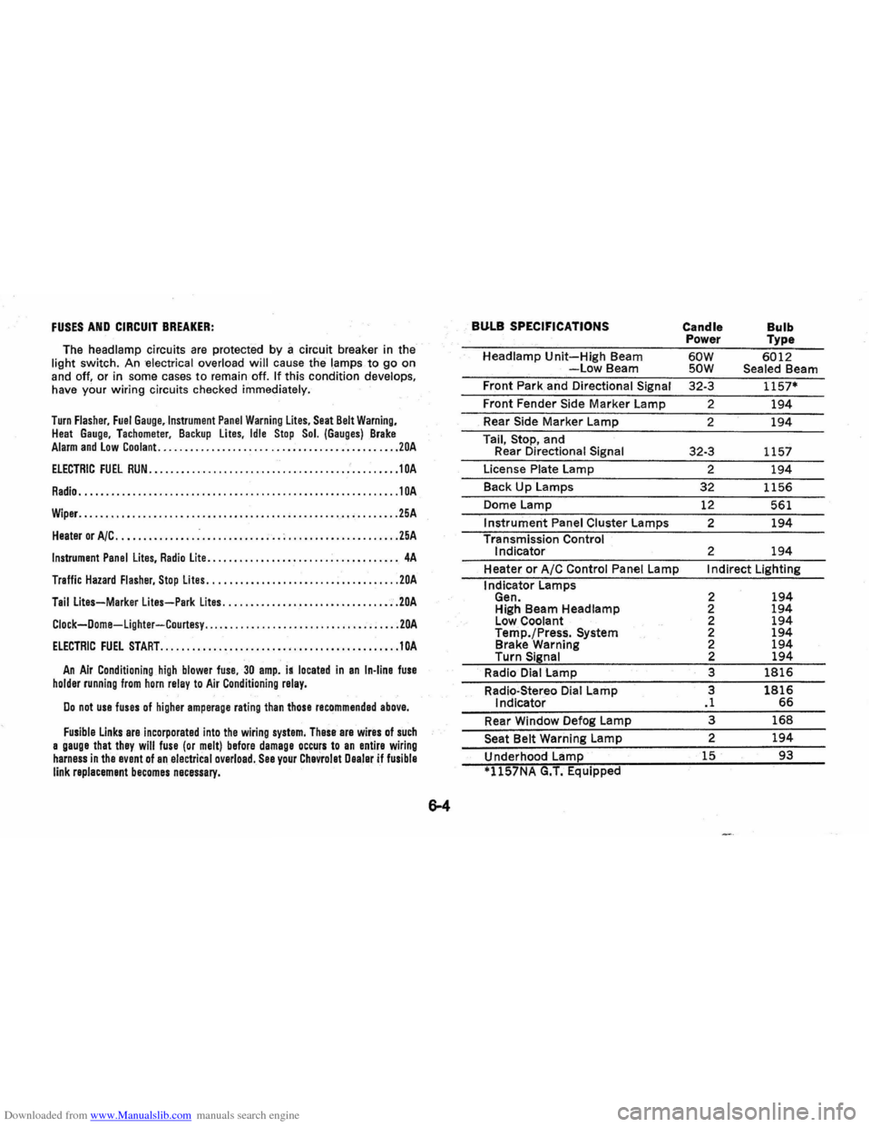
Downloaded from www.Manualslib.com manuals search engine FUSES AND CIRCUIT BREAKER:
The headlamp circuits are protected by a circuit breaker in the
light switch . An -electrical overload will cause the lamps to go on
and off. or in some cases to remain off. If this condition develops,
have your wiring circuits checked immediately.
Turn Flasher, Fuel Gauge,lnstrument Panel Warning Lites, Seat Belt Warning, Heat Gauge. Tachometer. Backup lites, Idle Stop Sol. (Gauges) Brake Alarm and Low Coolant. ............................................ 20A
ELECTRIC FUEL RUN ..................•........................•... 1 OA
Radio ............................................................ 10A
Wiper. ........................................................... 25A
Heater or A/C ............... .-............ ; .. ; ..................... 25A
Instrument Panel Lites, Radio Lite ...........•....... ................. 4A
Traffic Hazard Flasher, Stop Lites ...........•.•................•••... 20A
Tail Lites-Marker lites-Park Lites ...........•.............. .•..... 20A
Clock-Dome-Lighter-Courtesy ..... .......................... ; ..... 20A
ElECTRIC FUEL START ...•................•.•••.•......•.•.••...... 10A
An Air Conditioning high blower fuse, 30 amp. is located in an In-line fuse holder running from horn relay to Air Conditioning relay.
Do not use fuses of higher amperage rating than those recommended above.
Fusible Links are incorporated into the wiring system, These are wires of such a gauge that they will fuse (or melt) before damage occurs to an entire wiring harness in the event of an electrical overload. See your Chevrolet Dealer if fusible link replacement becomes necessary.
BULB SPECIFICATIONS
Headlamp Unit-High Beam -Low Beam
Front Park and Directional
Signal
Front Fender Side Marker Lamp
_ Rear Side Marker Lamp
Tail,
Stop, and
Rear Directional Signal
License Plate Lamp
Back
Up Lamps
Dome Lamp
Instrument Panel Cluster Lamps
Transmission Control
Indicator
Heater
or A/C Control Panel Lamp
I ndicator Lamps
Gen. High Beam Headlamp
Low Coolant
Temp./Press.
System Brake Warning
Turn Signal
Radio Dial Lamp
Radio-Stereo Dial Lamp
Indicator
Rear Window Defog Lamp
Seat Belt Warning Lamp
Underhood Lamp
*1l57NA G.T. Equipped
Candle
Bulb Power Type
60W 6012 SOW Sealed Beam
32-3
1157*
2 194
2 194
32-3 1157
2
194
32 1156
12 561
2
194
2 194
I ndirect Lighting
2
194 2 194 2 194 2 194 2 194 2 194
3 1816
3 1816 .1 66
3 168
2 194
15 93