1976 CHEVROLET VEGA flat tire
[x] Cancel search: flat tirePage 6 of 87
Downloaded from www.Manualslib.com manuals search engine BEFORE DRIVING YOUR VEGA
DRIVER CHECKLIST
Before Entering Car
1. See that windows , mirrors and
lights are clean.
2. Visually note inflation condition
of tires.
3. Check that area to rear
is clear
if about
to back up.
Before Driving Off
1. Lock all doors.
2. Position seat.
3. Adjust inside and outside
mirrors.
4. Fasten belt restraints.
5. Check that warning bulbs light
when key
is turned to start posi
tion.
6. Release parking brake (and see
that brake warning light turns
off).
7. Be sure you understand your
car and how to operate it safely.
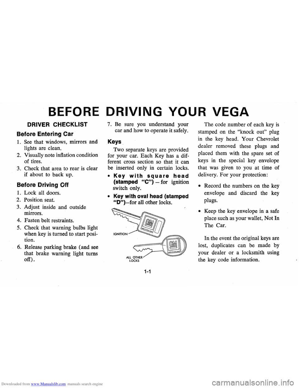
Keys
Two separate keys are provided
for your car. Each Key has a dif
ferent cross section so that it can
be inserted only in certain locks.
• Key with square head
(stamped Ole") -for ignition
switch only.
• Key with oval head (stamped
"D")~for all other locks.
LOCKS
1-1
The code number of each key is
stamped on the "knock out" plug
in the key head. Your Chevrolet
dealer removed these plugs and
placed them with the spare set of
keys in the special key envelope
that was given to you at time of
delivery.
For your protection:
• Record the numbers on the key
envelope and discard the key
plugs.
• Keep the key envelope in a safe
place such
as your wallet, Not In
The Car.
In the event the original keys are
lost, duplicates can be made by
your dealer or a locksmith using
the key code information.
Page 14 of 87
Downloaded from www.Manualslib.com manuals search engine Trailer Hauling
Since passenger cars are designed
and intended to be used primarily
as passenger conveyances, towing
a trailer will effect handling, dura
bility
and economy. Maximum
safety and satisfaction depends
upon proper use of correct equip
ment and avoiding overloads and
other abusive operation.
The maximum loaded trailer
weight which you can pull with
your car depends on what special
equipment has been installed on
your car. Chevrolet does not rec- ommend
towing any trailer
over
1,000 pounds gross trailer weight.
Information on trailer haul
ing capabilities, special equipment
required, and optional equipment
offered by Chevrolet
is available
from your Chevrolet Dealer or by
writing Chevrolet Motor Division,
Detroit, Michigan 48202
(or in
Canada by writing to General
Motors of Canada Limited,
Owner
Relations Department, Oshawa,
Ontario LlJ 5Z6).
To assist in attaining good han
dling of the car-trailer combination,
it
is important that the trailer
1-9
tongue load be maintained at ap
proximately 10%
of the loaded
trailer weight. Tongue loads can
be adjusted by proper distribution
of the load in the trailer, and can
be checked
by weighing separately
the loaded trailer and then the
tongue.
When towing trailers, tires should
be inflated to the highest inflation
pressures shown on the placard
affixed
to the left front door. The
allowable passenger and cargo
load, also shown on the same pla
card,
is reduced by an amount
eq ual to the trailer tongue load on
the trailer hitch.
Page 49 of 87
Downloaded from www.Manualslib.com manuals search engine 4. Attach the remammg jumper Engine Coolant
cable FIRST to the negative ter
minal (black color,
"-" or "N")
of the OTHER vehicle's battery,
(regardless of which vehicle has
the discharged
battery) and
THEN to the negative terminal
of the battery in THIS
car-thus
taking advantage of the flame
arrestor feature on the battery in
THIS car, should a spark occur.
5. Start engine in the vehicle that is
providing the jump start (if it
was not running). Let run a few
minutes, then start the engine in Jacking Instructions
the car that has the discharged
battery.
6. Reverse the above sequence
EXACTL Y when removing the
jumper cables, taking care to re
move the cable from
[he negative
terminal of the battery in THIS
car
as the FIRST step.
3-4
Preparation
• Park on level surface and set
parking brake firmly.
• Set automatic transmission in
park (manual transmission in
reverse).
• Activate hazard warning flasher.
Instructions
1. After removing spare wheel
and tire, jack, jack base, and
jack handle (wheel nut
wrench), proceed with chang
ing the wheel
as follows:
2. Remove hub cap or wheel
cover with flat end of wheel
nut wrench and loosen, but do
not remove nuts, by turning
counterclockwise.
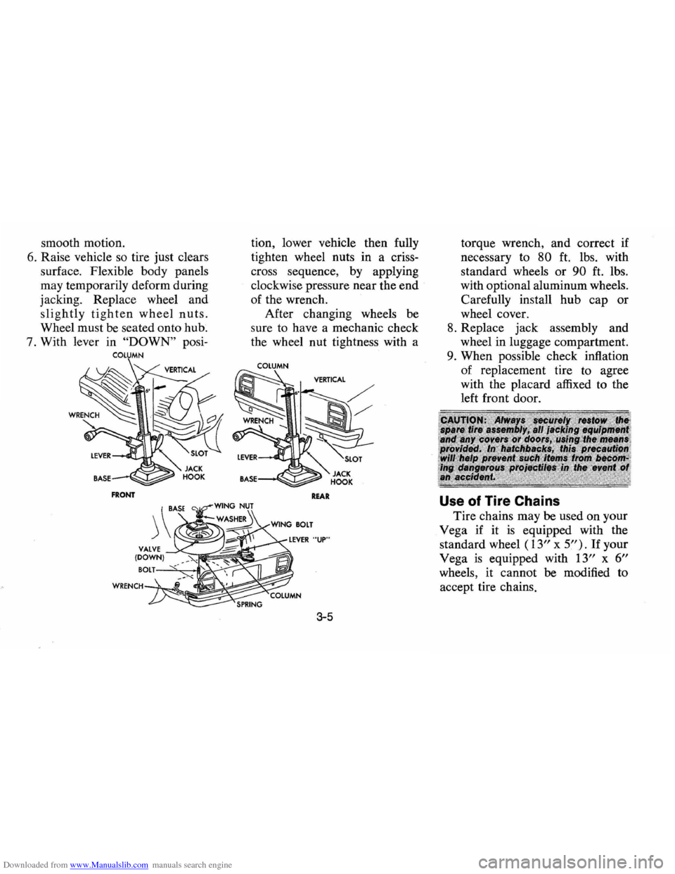
3. With column assembly seated
in base and lever in
"UP" posi
tion, insert jack hook in bum
per slot.
4. Base must sit flat with top of
column angled slightly away
from vehicle,
as shown in illus
tration.
5. Always operate jack with slow
Page 50 of 87
Downloaded from www.Manualslib.com manuals search engine smooth motion.
6. Raise vehicle so tire just clears
surface. Flexible body panels
may temporarily deform during
jacking. Replace wheel and
slightly tighten wheel nuts.
Wheel must be seated onto hub.
7. With lever in
"DOWN" posi
COLUMN
FRONT
tion, lower vehicle then fully
tighten wheel nuts in a criss
cross sequence, by applying
clockwise pressure near the
end
of the wrench.
After changing wheels
be
sure to have a mechanic check
the wheel nut tightness with a
COLUMN
REAR
3-5
torque wrench, and correct if
necessary to
80 ft. lbs. with
standard wheels
or 90 ft. lbs.
with optional aluminum wheels.
Carefully install
hub cap or
wheel cover.
8. Replace jack assembly and
wheel in luggage compartment.
9. When possible check inflation
of replacement tire to agree
with the placard affixed to the
left front door.
Use of Tire Chains
Tire chains may be used on your
Vega if it
is equipped with the
standard wheel
(13" x 5"). If your
Vega
is equipped with 13" x 6"
wheels, it cannot be modified to
accept tire chains.
Page 72 of 87
Downloaded from www.Manualslib.com manuals search engine TIRES
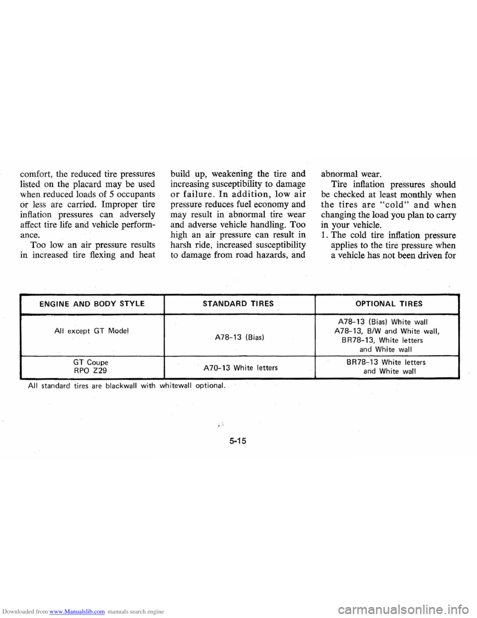
The factory installed tires on
your vehicle, shown in the Tire
Usage Chart, are engineered to pro
vide a proper balance of these per
formance characteristics for normal
vehicle operation:
• Endurance
• Handling
• Noise
• Ride
• Road Hazard Resistance
• Rolling Resistance
• Traction
• Tread Mileage
This section contains some tips
on how you can obtain maximum
benefit from these tires and your
investment in them.
Vehicle Loading
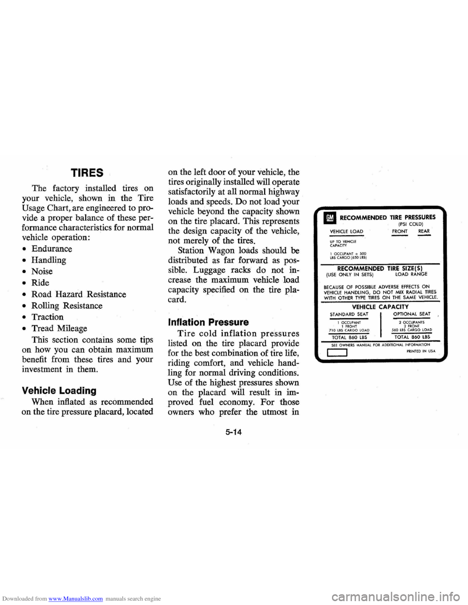
When inflated as recommended
on the tire pressure placard, located on
the left door of your vehicle,
the
tires originally installed will operate
satisfactorily at all normal highway
loads and speeds. Do not load your
vehicle beyond the capacity shown
on the tire placard. This represents
the design capacity of the vehicle,
not merely of the tires.
Station Wagon loads should
be
distributed as far forward as pos
sible. Luggage racks do not in
crease the maximum vehicle load
capacity specified on the tire pla
card.
Inflation Pressure
Tire cold inflation pressures
listed on the tire placard provide
for the best combination of tire life,
riding comfort, and vehicle hand
ling for normal driving conditions.
Use of the highest pressures shown
on the placard will result in
im
proved fuel economy. For those
owners who prefer the utmost in
5-14
II RECOMMENDED TIRE PRESSURES (PSI COlD) VEHICLE lOAD FRONT REAR ----UP TO VEHICLE CAPACITY
1 OCCUPANT + 500 lBS CARGO (650 lBS)
RECOMMENDED TIRE SIZE(S) (USE ONLY IN SETS) LOAD RANGE
BECAUSE OF POSSIBLE ADVERSE EFFECTS ON VEHICLE HANDLING, DO NOT MIX RADIAL TIRES WITH OTHER TYPE TIRES ON THE SAME VEHICLE.
VEHICLE CAPACITY STANDARD SEAT OPTIONAL SEAT
1 OCCUPANT 2 OCCUPANTS 1 fRONT 2 FRONT 710 lBS CARGO LOAD 560 LBS CARGO LOAD TOTAL 860 lBS TOTAL 860 lBS SEE OWNERS MANUAL FOR ADDITIONAL
INFORMATION
c::J PRINTED IN USA
Page 73 of 87
Downloaded from www.Manualslib.com manuals search engine comfort, the reduced tire pressures
listed on the placard may
be used
when reduced loads of 5 occupants
or less are carried. Improper tire
inflation pressures can adversely
affect tire life and vehicle perform
ance. Too
Iowan air pressure results
in increased tire flexing and heat
ENGINE AND BODY STYLE
All except GT Model
GT Coupe
RPO Z29
build up, weakening the tire and
increasing susceptibility to damage
or failure. In addition, low air
pressure reduces fuel economy and
may result in abnormal tire wear
and adverse vehicle handling. Too
high an air pressure can result in
harsh ride, increased susceptibility
to damage from road hazards, and
STANDARD TIRES
A78-13 (Bias)
A70-13 White letters
All standard tires are blackwall with whitewall optional.
f'"
5-15
abnormal wear.
Tire inflation pressures should
be checked at least monthly when
the tires are "cold" and when
changing the load you plan to carry
in your vehicle.
1. The cold tire inflation pressure
applies to the tire pressure when
a vehicle has not been driven for
OPTIONAL TIRES
A78-13 (Bias) White wall
A78-13, B/W and White wall,
BR78-13, White letters
and White wall
BR78-13 White letters
and White wall
Page 74 of 87
Downloaded from www.Manualslib.com manuals search engine for 3 hours or more, or driven
less than 1 mile.
2 .
It is normal for tire pressures to
increase 4-8
PSI when the tires
become hot from driving. Do not
"bleed" (reduce tire inflation
pressures) after driving your
vehicle. Bleeding serves to in
crease tire flexing and heat build
up which can result in tire dam
age and failure.
3. For sustained driving at turn
pike speeds, cold inflation
pressures should be increased 4
PSI above the recommended
cold inflation pressures on the
tire placard up to a maximum of
32
PSI for load range Btires, 36
PSI for load range C, and 40 PSI
for load range D. Sustained
speeds above 75 mph are not
recommended when the 4
PSI
adjustment would require pres
sures greater than the maximum
pressures above.
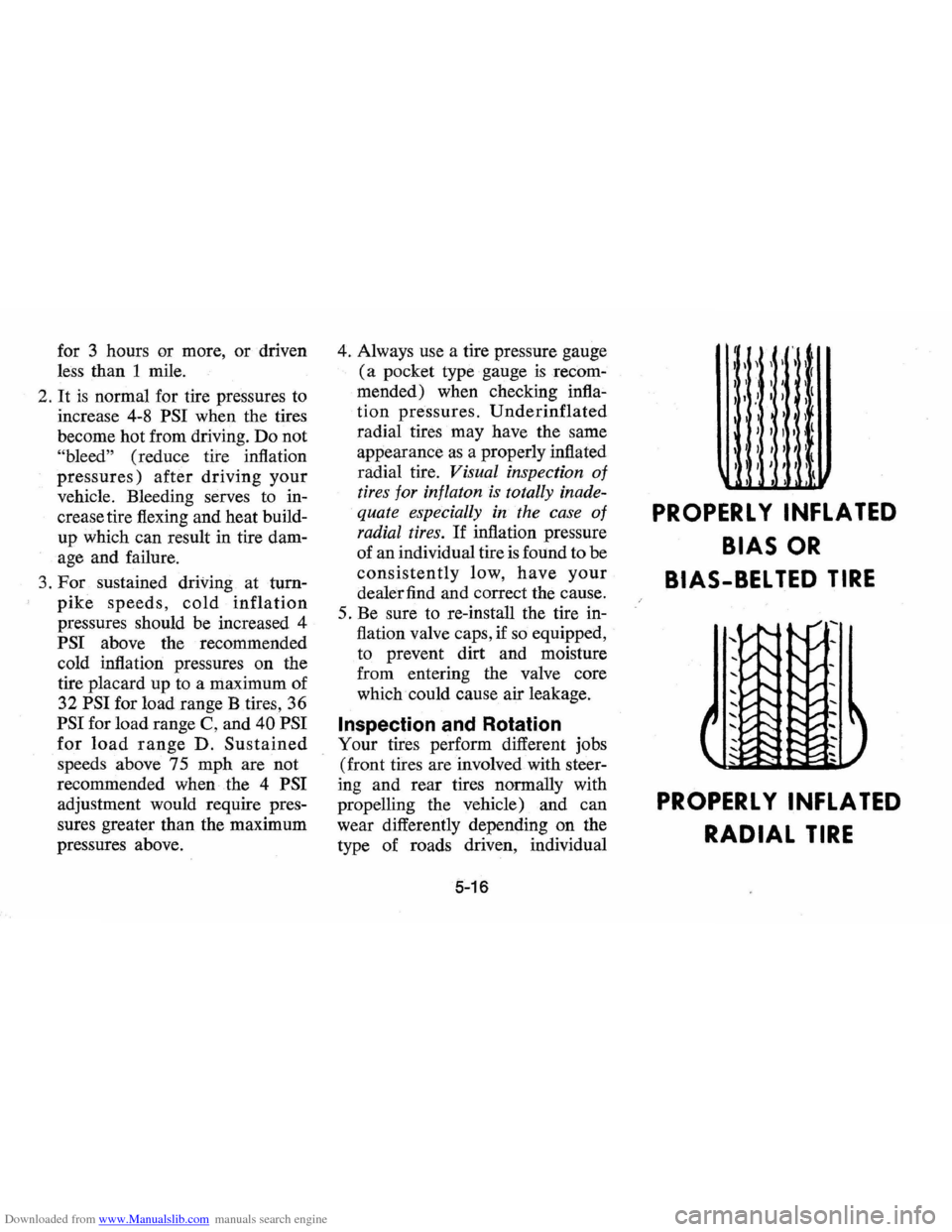
4. Always use a tire pressure gauge
(a pocket type gauge is recom
mended) when checking
infla~
tion pressures. Underinflated
radial tires may have the same
appearance
as a properly inflated
radial tire.
Visual inspection of
tires for inflaton is totally inade
quate especially in the case
of
radial tires. If inflation pressure
of an individual tire
is found to be
consistently low, have your
dealer find and correct the cause.
5. Be sure to re-install the tire in
flation valve caps, if
so equipped,
to prevent dirt and moisture
from entering the valve core
which could cause air leakage.
Inspection and Rotation
Your tires perform different jobs
(front tires are involved with steer
ing and rear tires normally with
propelling the vehicle) and can
wear differently depending on the
type of roads driven, individual
5-16
1\ II(
" I I ,t " I' ,I
I' I I j , I I I
I I , I I I I
I I I I I I
I 1
PROPERL Y INFLATED
BIAS OR
BIAS-BEL TED TIRE
PROPERL Y INFLATED
RADIAL TIRE
Page 76 of 87
Downloaded from www.Manualslib.com manuals search engine a~~~
DO NOT DO NOT
w~ ~"" "." !d'"
REPAIR AREA RADIAL TIRES
Tire Repair
Temporary repair patches or any
repairs made from the outside of
the tire are not recommended ex
cept in emergencies. Such "stop
gap"
devices as plugs and aerosol
type sealants are not recommended
for more than
100 miles of driving
at speeds not over
50 mph. A per
manent vulcanized repair (plug
and patch) applied from inside the
tire should be made
as soon as pos
sible. The installation of an inner
tube in a damaged tubeless tire
is not a recommended repair pro
cedure.
If an air loss occurs while
driving, do not attempt
to drive on
the deflated tire more than neces
sary to stop safely. Driving even a
short distance on a deflated tire can
damage a tire beyond repair.
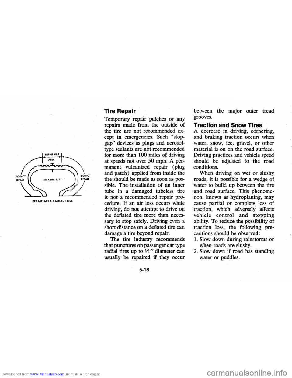
The tire industry recommends
that punctures
on passenger car type
radial tires up to
%" diameter can
usually be repaired if they occur
5-18
between the major outer tread
grooves.
Traction and Snow Tires
A decrease in driving, cornering,
and braking traction occurs when
water , snow, ice, gravel,
or other
material
is on on the road surface.
Driving practices and vehicle speed
should be adjusted to the road
conditions. When driving on wet or slushy
roads , it
is possible for a wedge of
water to build up between the tire
and road surface. This phenome
non, known
as hydroplaning, may
cause partial or complete loss of
traction, which adversely affects
vehicle
control and stopping
ability. To reduce the possibility of
traction loss, the following pre
cautions should
be observed:
1 .
Slow down during rainstorms or
when
roads are slushy.
2. Slow down if road has standing
water or
pUddles.