1976 CHEVROLET MONTE CARLO check engine
[x] Cancel search: check enginePage 3 of 102

Downloaded from www.Manualslib.com manuals search engine ,
BEFORE DRIVING YOUR CHEVROLET
DRIVER CHECKLIST
Before Entering Car
1. See that windows ; mirrors and
lights are clean.
2. Visually note inJIation condition
of tires.
3. Check that area to rear is clear
if about to back up.
Before Driving Off
1. Lock all doors.
2. Position seat, jmd adjust head
restraints, if
so ¢quipped.
3. Adjus!insidean'd outside mirrors.
4. Fasten seat belts.
5. Check that warning bulbs light
when key
is turned to start
position. .
6. Release parking brake ( and see
that brake warning light turns
off). ,
7. Be sure you understand your car
and how
to 'operate it safely.
Keys
Two separate keys are provided
for your car. Each key has a
differ
ent cross section so that it can be
inserted only in certain locks.
• Key with s qua r e hell d
(stamped "e") -for ignition
switch only.
• Key with oval head (stamped
"O")-for all other locks.
,
The code number of each key is
All OTHeR LOCKS
1-1
stamped on the "knock out" plug
in the '
key-bead. Your Chevrolet
dealer removed these plugs
and,.
placed them with the spare set of
keys in the special key envelope
. that was given to you at time of
delivery.
For your protection:
• Record the numbers on the key
envdope and discard the key
plugs.
• Keep the key envelope in a safe
place such
as YOII! wallet, NOT
IN THE CAR.
In the event
the original keys are
lost,
dl!plicates can be made by
your dealer or a locksmith using the
key code information.
Be sure to lock the Klove box
or console
90mpartment and re~
move the key from the car whenever
it is necessary to leave the ignition
key with
an attendant.
Page 9 of 102

Downloaded from www.Manualslib.com manuals search engine o To fasten the· detachable shoul
der belt,
unstow it and place the
knob on the shoulder belt end
into the keyhole on the lap belt
latch plate.
(The latch is de
signed
so that this attachment
can only be completed before
fastening the lap belt.) Tilt the
knob as necessary , to pass it
through the slot.
Pull the knob
firmly upward to seat it at the
narrow end of the keyhole, then fasten
the lap belt. Reverse this
procedure when removing and
restowing the shoulder belt.
o The detachable shoulder belts
are lengthened and shortened in
the same manner as center seat
lap belts.
o The detachable shoulder belt
should have sufficient slack to
in
sert a fist's width between your
chest and the belt. This can be
checked
by inserting a clenched
fist between · the belt and your
chest with thumb against chest
and
back of hand facing upward.
Belt Restraint Inspection
o Periodically inspect belts,
buckles, adjustable latch plates,
1-7
retractors, reminder systems,
guide loops, clips,
and anchors
for damage that could lessen the
effectiveness
of the retraint
system.
o Keep sharp edges and damaging
objects away from belts, and
other parts of restraint system.
o Replace belts if cut, weakened,
frayed,
or subjected to collision
loads.
o Check that anchor mounting
bolts are tight.
o Have questionable parts re
placed.
o Keep belts clean and dry.
o Clean only with mild soap solu
tion and lukewarm water.
o Do not bleach or dye belts since
. this may severely weaken belts.
Head Restraints
o Head restraints are designed to
help reduce injuries due to
"whiplash".
Page 12 of 102
Downloaded from www.Manualslib.com manuals search engine Trailer Halllihg
Since passenger cars are designed
and
i~ended to be used primarily
as passenger conveyances, towing
a
trailer will effect handling , dura-
" bility and economy. Maximum
safety and satisfaction depends
upon proper use of correct equip
ment and avoiding overloads and
other abusive operation.
The maximum loaded trailer
weight which you can pull with
your car depends on what special
equipment has been installed
on
your car. Chevrolet does not rec-ommend
towing any trailer
over
1,000 pounds gross trailer weight
unless the car has the proper (!quip
ment .
Information on trailer haul
ing capabilities, special equipment
required , and optional equipment
offered by Chevrolet
is available
from your Chevrolet Dealer or by
writing Chevrolet Motor Division,
Detroit, Michigan
48202 (or in
Canada by writing to General
Motors of Canada Limited,
Owner
Relations Department, Oshawa,
Ontario LlJ 5Z6).
To assist in attaining good han
dling of the car-trailer combination,
it is important that the trailer
1-10
tongue load be maintained at ap
proximately
10% of the loaded
trailer weight. Tongue loads can
be adjusted by proper distribution
of the load in the trailer, and can
be checked
by weighing separately
the loaded trailer and then the
tongue.
When towing trailers, tires should
be inflated to the highest inflation
pressures
shown :on the placard
affixed to
the left' front door. The
allowable passenger and cargo
load , also shown
on the same pla
card,
is reduced by an amount
eq ual to the trailer tongue load on
the trailer hitch.
Page 20 of 102
Downloaded from www.Manualslib.com manuals search engine such as changing lanes on an ex
pressway , the steering wheel
is not
turned back sufficiently after com
pleting the turn to automatically
cancel the turn signal.
For con
venience
,in such maneuvers, the
driver can flash the turn signals by
moving the turn signal lever part
way (to tlie first stop) and holding
it there. The lever returns to the
neutral
or canceled position when
the driver releases his hold on the
lever. A
green light on the instrument
cluster flashes to indicate proper
operation of the front and rear turn
signal lamps.
If the indicator lamp
. remains on and does not flash,
check for a defective lamp bulb.
If
the indicator fails to light when
the lever
is moved , check the fuse
and indicator bulb.
Power Steering
If the steering system power as
sist fails due to some malfunction, or
because the. engine has stalled,
the car can still be steered. How
ever; much greater effort is re
quired particularly in sharp turns.
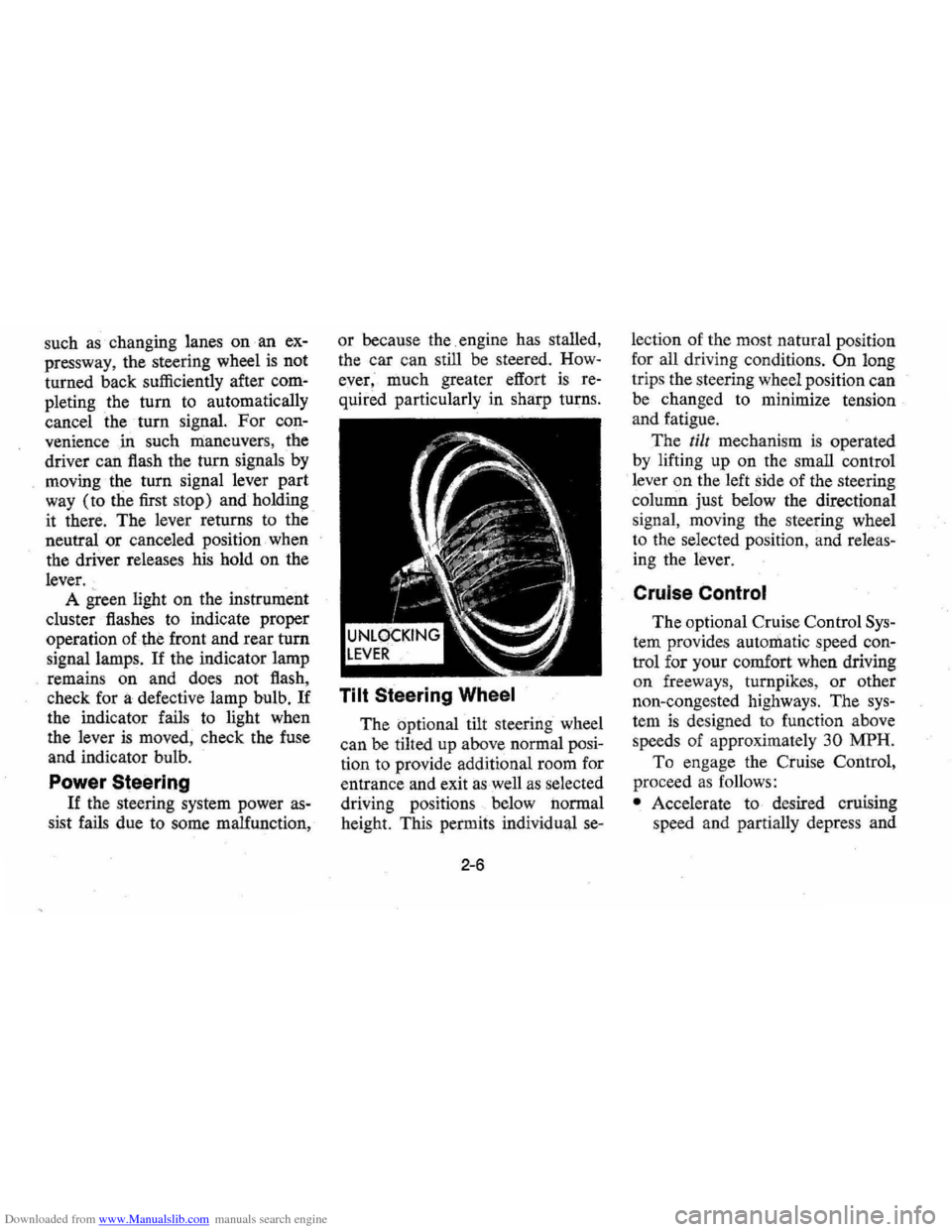
Tilt Steering Wheel
The optional tilt steering wheel
can be tilted up above normal posi
tion to provide additional room for
entrance and exit
as well as selected
driving positions below normal
height. This permits individual
se-
2-6
lection of the most natural position
for all driving conditions.
On long
trips the steering wheel position can
be changed to minimize tension
and fatigue.
The
till mechanism is operated
by lifting up on the small control
lever
on the left side of the steering
column just below the directional
s ignal , moving the steering wheel
to the selected position, and releas
ing the lever.
Cruise Control
The optional Cruise Control Sys
tem provides automatic speed con
trol for your comfort when driving
on freew a
ys, turnpikes, or other
non-congested highways. The
sys
tem is designed to function above
speeds of approximately
30 MPH.
To enga ge the Cr:uise Control,
proceed
as follows:
• Accelerate to desired cruising
speed and partially depress and
Page 23 of 102
Downloaded from www.Manualslib.com manuals search engine NOTE: "Riding the brake" by rest
ing your foot on the brake pedal
when not intending to brake can
cause abnormally
high brake tem
peratures, excessive lining wear and
possible damage to the brakes,
in
addition to wasting.gasoline.
Self-AdjustingiBrakes
• Brakes on th(i; ' car (except for ••.
the parking }prake) are self
adjusting, designed to eliminate
periodic
brake adjustments.
• Drum brake adjustment is made
automatically
as the brakes are
applied while car is moving
backwards.
• Disc brake . adjustment is made
automatical1y with each brake
application.
• If excess brakep~dal travel de
velops, drive alternately back-
ward and forward (several
times) and apply brakes firmly
in each direction.
• See )lour dealer if normal pedal
travel is not restored, or if there
is a rapid increase in pedal travel,
which could be a sign of other
brake trouble.
See y6ur dealer also if
adjust
ment of the parking brake is
required;
REMINDER: The front disc
brakes have a built-in wear indica
tor that is designed to make a high
frequency squealing,
or cricket-like
warning sound when the linings are
worn to where replacement
is re
quired. The sound will occur inter
mittently or continuously when
wheels are rolling, but will
dis
appear when the brake pedal is ap-
2-9
plied firmly. See also the various
brake checks listed in the
Chevro
let maintenance schedule folder.
Headlight Beam Switch
"High" and "low" headlight
beams are controlled by the floor
button at your left foot. The
indi
cator, located next to the speed
ometer dial, will light up when the
high beams are in use.
Page 26 of 102
Downloaded from www.Manualslib.com manuals search engine ble'can be located and corrected .
. Driying the car with low oil pillS'
sure can:cause · serious ' engine
damage.
Genera~orlndicator Light
The red light will go on when
the
ignition key is in the "on " posi,
tion, b~f before the engine is
started.'J\fter the engine starts, the
light .
sho'uld go out and remain out.
If the Hght remains on when engine
is runlling, have your Authorized
Chevrolet Dealer locate and cor,
reCI the trouble as soon as possible,
Engine Temperature
Indicator Light
, This indicator light is provided
in the instrument cluster to quickly
warn
of an overheated engine. With
the ignition switch in the
5T AR T
position, the red TEMP indicator
will light to let you know that it is
operating properly. When
the engine
is started , the
red light will go out immediately,
It will light up at no other time
unless for some reason the engine
.
reaches a dangerously high oper,
atingtemperature. If the light
comes on during
extreme driving
conditions, such
as an extended
idle, turn
off the air conditioner (if
used }.and run the engine slightly
faster than
idle. speed with the
transmission in neutral gear .
If the
light does not go
off within a short
period of time
(F2 minutes), then
tum the engine off until the cause
of the.
overheating is corrected;
Glance at the
Ins.trument cluster
frequently as you drive to see if
this light
is on. '
Brake System Warning
Light
.
The service .. brake system is a
dual system designed
so that. one
part will provide some braking
2-12
action in the event of loss of hy'
draulic pressure in the other part of
the system.
If the ,warning light
labeled
"BRAKE," located in the
speedometer face, comes on .and
stays on when the ignition
is on and
'after · the brakes have been firmly
applied, it may indicate that
there
is a malfunction in one part of the
brake system.
'
•
As ~ reminde;, the light is de,
signed:to
come on with the park,
ing brake applied and the ignition
on.
• The light is also designed to
come on, during ;engine starting
to verify that the bulb is operating
. properly.
• Have system repaired '. if light
does not come
on' during check.
• This warning light, is not a sub
stitute for the visual check of
brake fluid level required
as part
of normal maintenance.
Page 27 of 102
Downloaded from www.Manualslib.com manuals search engine If the light comes oQ:
• The :parking brake control is not
fully
relea sed or, ,,:
• The service brake system is
partially inoperative .
What to do :
1. Check that the parking brake
is released. If it is ...
2.
Pull off the road and stop, care
fully-remembering that:
'
•
Stoppin g "distances may be
greater. ' '0:
• Greater pMal effort may be
required .: ;
• Pedal
travel may be greater.
3. Try out b~ake operati on by start
ing and
stopping on road shoul
der-then :
• If you judge such operation to
be safe , proceed cautiously at
a safe speed to neare st dealer
for repair.
• Or have car towed to dealer
}or repair .
Continued operation ' of the car in '
this condition
is dangerous.
Headlight High Beam
Indicator Light
The headlights of your ' car have '
high and
low, beams to provi(je you
with proper night-time visibility
for most . driving
conditioQs. The
"low" beams are used during most
city driving. The
"high" beams are
especially useful when
drh;ing on
dark roads since
they provide ex
cellent long range illumination.
The headlight beam
indicator will
be on whenever the high beams or
"brights" are in use. The Headlight
Beam
Switch controls the headlight
beams (see
Page 2-9).
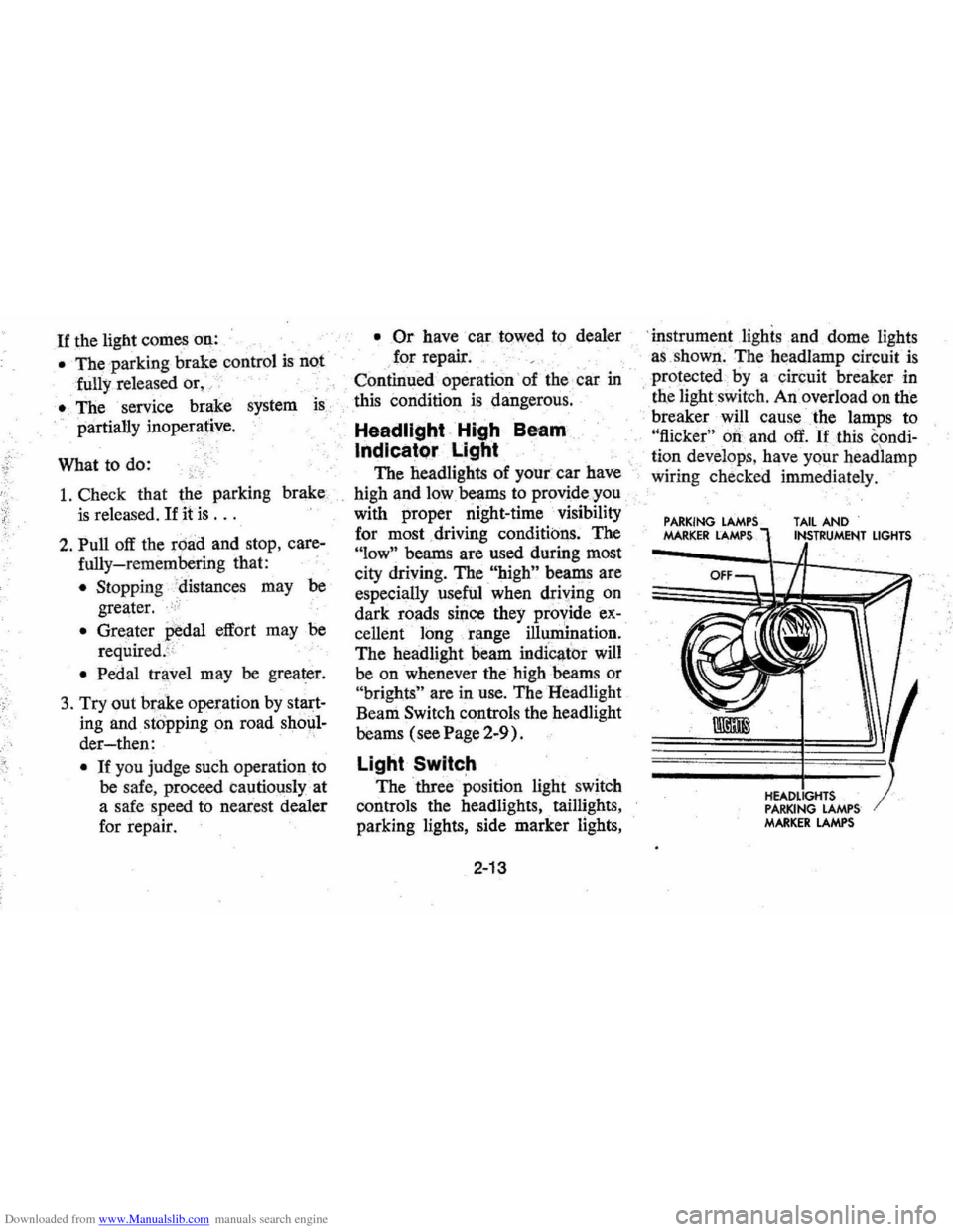
Light Switch
The three position light switch
controls the headlights " taillights,
parking lights, side marker lights,
2-13
'i nstrument lighis and dome lights
a s ,shown . The headlamp circuit
is
protected·· by a circuit breaker in
, tne lightswit ch . An overload on the
breaker will cause the lamps to
"flicker" 00 and off. If this condi
ti on develop s, hav e your headlamp
wiring check ed immedi ately.
PARKING MARKER LAMPS TAIL AND
PARKING LAMPS MARKER LAMPS
LIGHTS
Page 30 of 102
Downloaded from www.Manualslib.com manuals search engine fall low enough to freeze the solu
tion.
• Check washer fluid level regu
larly-do it frequently when the
weather
is bad.
• Use a fluid such as GM
OPTIKLEEN · to help prevent freezing
damage, and
to provide
better cleaning.
• Do not use radiator anti-freeze
in windshield washer; it could
cause paint damage.
• In cold weather, warm the wind
shield with defrosters before us-
2-16
ing washer-to help prevent ic
ing that may seriously obscure
vision.
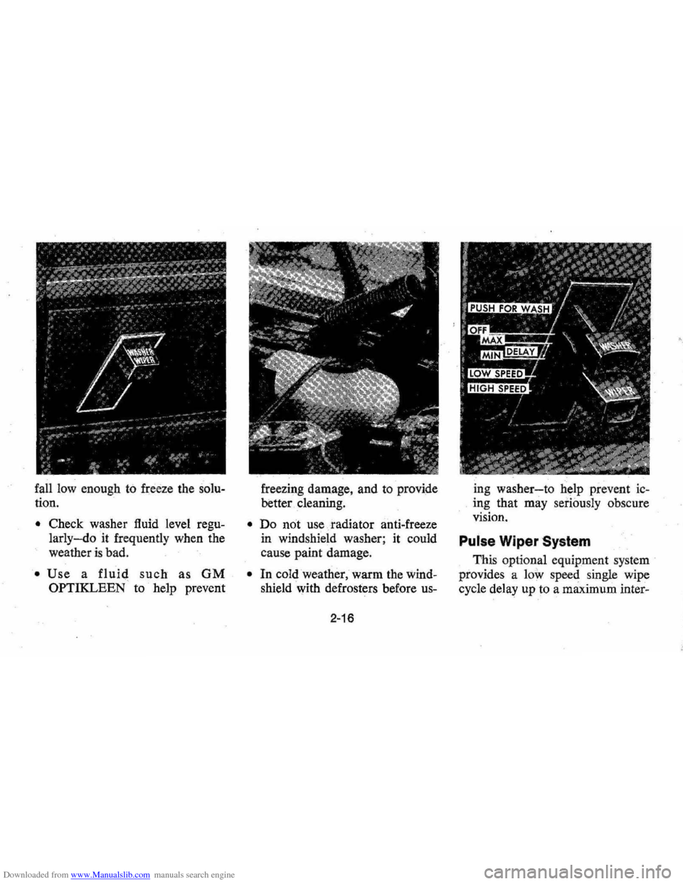
Pulse Wiper System
This optional equipment system
provides a low speed single wipe
cycle delay up
to a maximum inter-