1976 CHEVROLET MONTE CARLO ignition
[x] Cancel search: ignitionPage 26 of 102
Downloaded from www.Manualslib.com manuals search engine ble'can be located and corrected .
. Driying the car with low oil pillS'
sure can:cause · serious ' engine
damage.
Genera~orlndicator Light
The red light will go on when
the
ignition key is in the "on " posi,
tion, b~f before the engine is
started.'J\fter the engine starts, the
light .
sho'uld go out and remain out.
If the Hght remains on when engine
is runlling, have your Authorized
Chevrolet Dealer locate and cor,
reCI the trouble as soon as possible,
Engine Temperature
Indicator Light
, This indicator light is provided
in the instrument cluster to quickly
warn
of an overheated engine. With
the ignition switch in the
5T AR T
position, the red TEMP indicator
will light to let you know that it is
operating properly. When
the engine
is started , the
red light will go out immediately,
It will light up at no other time
unless for some reason the engine
.
reaches a dangerously high oper,
atingtemperature. If the light
comes on during
extreme driving
conditions, such
as an extended
idle, turn
off the air conditioner (if
used }.and run the engine slightly
faster than
idle. speed with the
transmission in neutral gear .
If the
light does not go
off within a short
period of time
(F2 minutes), then
tum the engine off until the cause
of the.
overheating is corrected;
Glance at the
Ins.trument cluster
frequently as you drive to see if
this light
is on. '
Brake System Warning
Light
.
The service .. brake system is a
dual system designed
so that. one
part will provide some braking
2-12
action in the event of loss of hy'
draulic pressure in the other part of
the system.
If the ,warning light
labeled
"BRAKE," located in the
speedometer face, comes on .and
stays on when the ignition
is on and
'after · the brakes have been firmly
applied, it may indicate that
there
is a malfunction in one part of the
brake system.
'
•
As ~ reminde;, the light is de,
signed:to
come on with the park,
ing brake applied and the ignition
on.
• The light is also designed to
come on, during ;engine starting
to verify that the bulb is operating
. properly.
• Have system repaired '. if light
does not come
on' during check.
• This warning light, is not a sub
stitute for the visual check of
brake fluid level required
as part
of normal maintenance.
Page 32 of 102
Downloaded from www.Manualslib.com manuals search engine vides ventilation . coillfort , made
possible
by the additionaf air veilt
provisions ' in the rear 1:>ody lock
pillar. Another feature of the
sys
tem is continuous low:speed opera
tion of the heater and air condi
tioner blower , resulting in an un
interrupted
supply of outside air
flOw into the car whenever the
ignition switch is.on. With
the side windows closed,
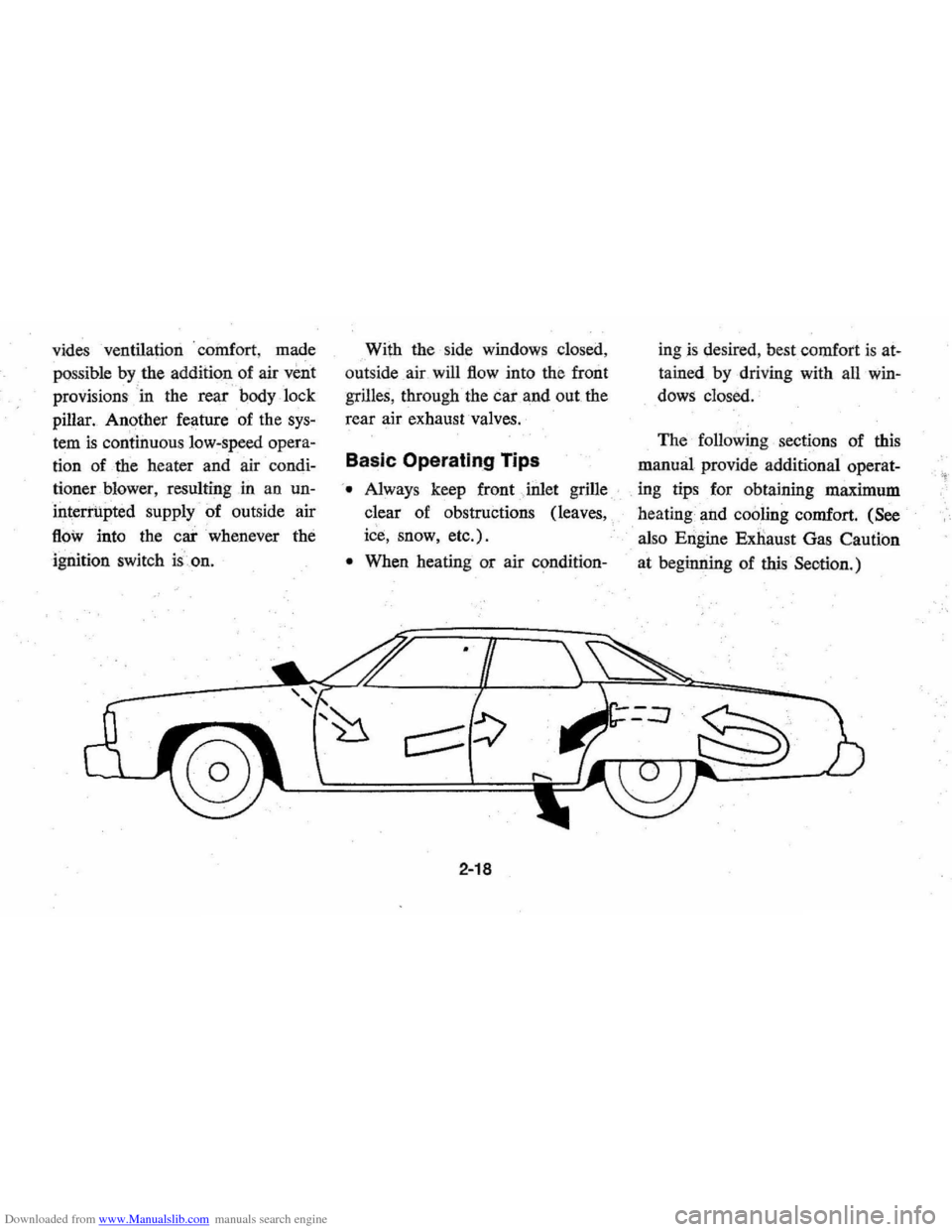
out side air will
flow into the front
grilles, through the car and out the
rear air exhaust valves.
Basic Operating Tips
'. Always keep front Jnlet grille
clear of obstructions (leaves,
ice, snow, etc.).
• When heating or air condition-
2-18
ingis desired , best comfort is at
tained by driving with all win
dows closed.
The following sections of this
manual provide additional operat-
. ing tips for obtaining maximum
heating and
cooling comfort. (See
also Engine Exnaust Gas Caution
at beginning of
this Seotion.)
Page 33 of 102
Downloaded from www.Manualslib.com manuals search engine Heater
The defrosting and
defogging
systenl assists in provid,
ing good visibility through desig
nated areas of the windshield under
most
inClement'Weather conditions.
For immediate operation of the ve
hicle, the windshield should be
scraped clear.
'
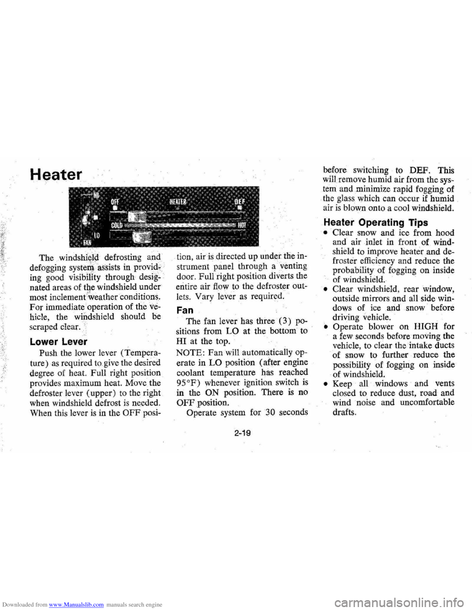
Lower Lever
Push the lower lever (Tempera
ture) as required to,give the desired
degree of heat. Full right position
provides maximum heat.
Move the
defroster lever (upper) to the right
when windshield defrost
is needed.
When this lever
is in the OFF posi- tion,
air is directed
up under the in
strument panel through a'venting
door, Full right position diverts the
entire air
flow to the defroster out
lets, Vary
lever as required.
Fan
The fan lever has three (3) po
sitions from LO at the bottom to
HI at the top.
NOTE: Fan will automatically op
erate in LO position (after engine
coolant temperature has reached
95
OF) whenever ignition switch is
in the ON position. There is no
OFF position.
Operate system for
30 seconds
2-19
before switching to DEF. This
will remove humid air from the
sys
tem and ,minimize rapid fogging of
the glass which can occur
if humid
air is blown onto a coo l windshield.
Heater Operating Tips
• Clear snow and ice from hood
and air inlet in front
of wind
shie ld to improve heater and de
frost er efficiency and reduce the
probability of fogging on inside
of windshield.
• Clear windshield, rear window,
outside
mirrors , and all side win
dows of ice ,and snow before
driving vehicle.
• Operate blower on HIGH for
a few seconds before moving the
vehicle, to clear the intake ducts
of snow to further reduce the
pos sibili
ty of fogging on inside
of windshield.
• Keep all windows and vents
clo sed to reduce dust, road and
wind noise and uncomfortable
drafts .
Page 40 of 102
Downloaded from www.Manualslib.com manuals search engine To Tune Your Stereo Radio
• Tune radio to an FM Stereo sta
tion (one which makes the indi
cator light come on with a steady
glow).
.
. •
Tune .ihe lever behind the sta
tion .selector knob until volume
from . front and rear speakers
sounds equal. .
• Regulate volume and tone con~
troIS' as required.
Stereo Tape System
The optional !ltereo Tape Player
provides prerecorded stereo
pro
grams for you r enjoyment.
To play, turn ignition switch to
"ON" or "ACC " position and in
sert cartridge throu gh tape door
with label
side up arid open end in
first. Tape will play through aU four
program s in succe ssion, then replay
in same sequence. Balancing the
speakers
is not required as this ad- justment
has.
be~n made at the fac
tory. Should it become necessary to
make ihis
adjustPlent, see your
Chevrolet dealer.
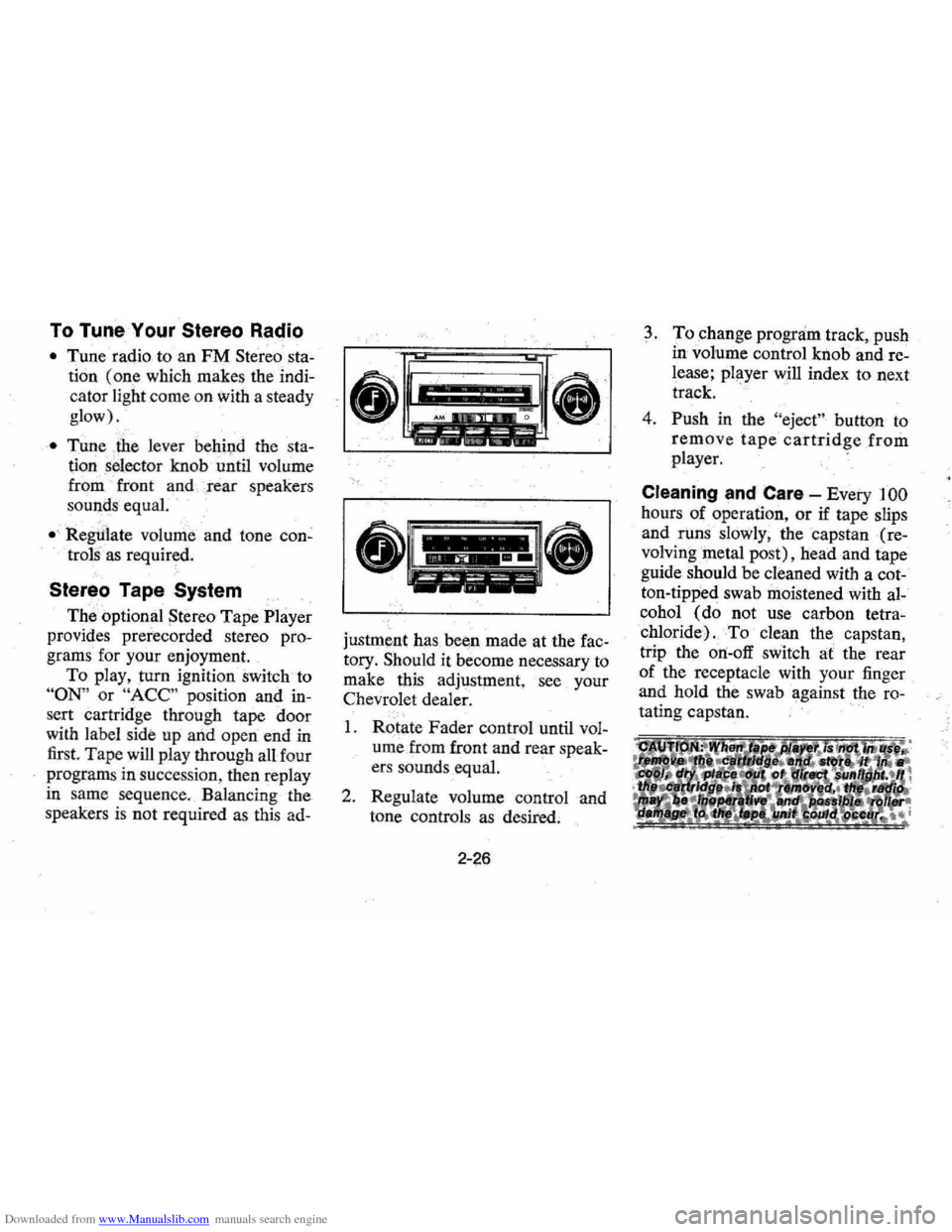
I. Rotate Fader control until vol
ume from front and rear speak-
ers sounds equal. .
2. Regulate volume control and
tone controls as
desired,
2-26
3. To change program track, push
in volume control knob and re
lease; player will index to next
track. .
4.
Push in the "eject " button to
remove tape cartridge from
player.
Cleaning and Care -Every 100
hours of operation, or if tape slips
and
runs slowly , the capstan (re
volvingmetal post), head and tape
guide should be cleaned with a cot
ton-tipped swab moistened with al
cohol
(do not use carbon tetra
chloride)
.To clean the capstan,
trip the
on-off switch at the rear
of the receptacle with your finger
and hold the swab
~gainst the ro-
tating capstan .
' ..
Page 46 of 102
Downloaded from www.Manualslib.com manuals search engine ond seat forward for access to
the third seat area.
2. Lift third seat back hinged filler
panel
rearward onto seat back,
then, grasp seat back handle and
lift seat
back. upward until it
locks
in the full "up" position
(see illustration
0).
Keep belt restraints and buckles
clear of mechanism when folding
seats,to prevent damage to these
belt
systems. C·>·i
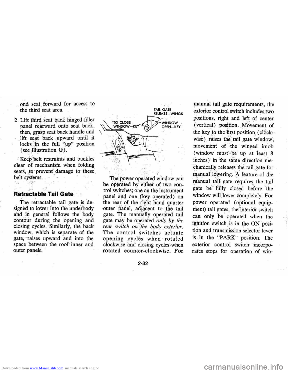
Retractable Tail Gate
The retractable tail gate is de
signed to
lower into the underbody
and in general follows the body
contour during the opening and
closing cycles. Similarly, the back
window, which
is separate of the
gate, raises upward and into the
space between the roof inner and
outer panels.
TAIL GATE RELEASE~WINGS
'TO CLOSE --C~WINDOW ~ WINDOW-KEY ~:/ OPEN-KEY
The power operl)ted window can
be
op~rated by either of two con
trol switches; one on the instrument
panel
~nd one (key operated) on
the
rea~ of the tight hand quarter
outer
panel, adjacent to the tail
gate. The manually operated tail
gate
may" be operated only by the
rear switch on the body exterior.
The control switches actuate
openingcycle.s when rotated
clockwise and closing cycles when
rotated counter-clockwise. For
2-32
manual tail gate requirements, the
exterior control switch includes two
positions, right and left of center
(vertical) position. Movement of
the
key to the first position (cl()ck
wise) raises the
tail gate window;
movement of the winged knob
(window must
Be up at least 8
iqches) in the same direction me
chanical!>: releases the tail gate for
manual16wering. A feature of the
~anual tap gate requires the tail
gate be
fUlly closed before the
window
will lower completely. For
power operated (optional equip
ment) tail gates, thei,nterior switch
can only be operated when the
ignition switch
is in the ON posi
tion and transll)ission selector lever
is in the "PARK" position. The
exterior control switch incorpo
rates stops for operation of win-
< I
Page 50 of 102

Downloaded from www.Manualslib.com manuals search engine 0: K.TO JUMP START
~ DARKENED INDICATOR WITH GREEN DOT .. . •• BATTERY CHARGE OK • FLUID LEVEL OK
Jump Start Procedure:
1. Wear eye protection and remove
rings, metal watch bands, and
other metal jewelry.
3-3
2. Set parl<;ing brake ,firmly. I'lace
automatic transmission in
"PARK" in both vehicles (don't
let
vehicles touch); turn ignition
key to LOCK in car with dis
charged battery (Neutral and
"OFF" in cars with,manual
transmissioJl). Also turn off
lights, heater,
ancl all unh~cessary
electrical loads.
3. Attach one end of a jumper
cable
to one battery's positive
terminal (identified
by a red
color, "+1', or "P" on the bat
tery case, post, or clamp), and
the other end
of the same cable
to the positive terminal of the
other battery.
Page 84 of 102
Downloaded from www.Manualslib.com manuals search engine Important
1. Keep your engine properly tuned. Certain engine malfunctions, particularly involving the electrical, car
buretion or ignition systems, may cause unusually high converter temperatures.
Do not continue to operate
your vehicle if you detect engine misfire, noticeable loss
of performance, or other unusual operating condi
tions.
A properly tuned engine will help avoid malfunctions that could damage the catalytic converter.
2. Do not park your car over combustible materials, such
as grass or leaves, which can come into contact
with the hot exhaust system and cause such materials to ignite under certain wind and weather conditions.
3. Do not push
or tow this vehicle to start. Under some conditions, this could damage the catalytic converter.
DISREGARD
OF THESE WARNINGS COULD CAUSE DAMAGE TO THE CATALYTIC
CONVERTER, TO THE VEHICLE, OR PROPERTY NEAR THE VEHICLE.
5-23
Page 94 of 102
Downloaded from www.Manualslib.com manuals search engine Glove Box ......................... 1·1 Harness, Safety (See Seat Belts) Hazard Wa rning Flasher. . . . . . . . . . . .. 3· t H ead lamp Flickering (Circuit Breaker) ........ 6-3 High Beam Dimmer Switch ..... _. .. 2 ·9 H igh Beam Indicator.... .. .. ...... 2· 13 Ught and Instrument Panel Switch....... .. .. .. .. .. .. . ... .. 2·13 Head Restraints. . . . . . . . . . . . . . . . . . .. 1·7 Heate r Operation .... , ........•...... 2·19 High Speed Operation During Break·In... .... ....... .... ii Tires ............................ 5·14 Hit ches, Trail er ..................... 1·10 Hood latch Maintenance ..•............. 5·12 Release .............. Inside Back Cove r Horn .............................. 2·7
"HOT" Light (See Engine
Temperature Light)
H ow
To Improve Your Gas Mileage Tips ..... ' ................ 5~21 Hub Caps, Replacing.... . . . . . . . . . . .. 3A Hydroplan ing ......... , ... ....• , , .. 5·18 Identificatio n Numbers Body ........................•.... 6-1 Engine ...................... , ... 6-1 Vehicle. . . . . . . • . • . . . • . • • . . . . . . . .. (j. 1 Ignition
Key s .... , .......... , ...• ...... 1-1, 2~2 Lock.. ........ .. .. .. .. .. .. .... .. 2·2 In Case Of Emerg ency ........... , , .. 3·1 Indic ator Lights
Brake .............. , .... , ....... 2-12
Electrical Charging (Gene rator) ..... 2-12
Engine Temperature ............ , .. 2- J 2 Oil Pressure.. . . . . . . . . . . . . . . . . . ... 2-11
In fant Restraining Methods .......... 1·8 Infant Safety Carrier ..... , ... , . • . . .. J·8 Inflation Pressure, Tires. . . .. . . . . . . . .. 5·14 Inle ts, Ventilation System ......•... ,. 2·17 Inside Rearview Mirro r ........•• ,. " 1·3 Instrume m Panel. . . . . . . . . . . . . • . . . .. 2-10
I nterior Appearance Care ......•..... 41 Jack Operation ...... ;." ., .. .. .. .. .... 3-4
Storage .... , . , . , , , , . , . . . . . . . . . . .. 3-5 Jump Starting With Booster Battery. .. 3-2 Key, Buzzer System ... , ... , ... , , . . . .. 2-2 Keys .............................. 1·1 Knocking Engine (See Fuel
Recommendation s)
Lacquer, Acrylic
Care .... , ........ ,' 4-5 Lane Change r and Turn Signal. . . . . .. 2·5 Lap and Shoulder Belts .. , . . . . . . . . . .. 1·6 Latches Door ............................ 1-2 Foldi ng Seat Back .. , ....•........ 1-3
Hood ................. ,..... . ... 5·1 2 Lig hter, Cigarette. .........•.. ... ... 2-15 Lights......... ........ .... ........ 6-3 Backup.......... .. .. .......... .. 6-3 Brake Warning. _, ..... , ....... " .. 2-1 2 Bright Beam Indicator. , . , , ...•. , .. 2· 13 Bright Beam Switch ... ".......... 2-9 Bulb Chart ............ , .......... &.3 Courtesy ....... : . . . . . . . . . . . . . . . .. 6-3 Engine Temperature Indicator. . . . .. 2-12 Generator Indicator ... , . . . . . . . . . .. 2-12 Hazard Flasher ... ..... , .... , . , . .. 3·1 Head lamp Circuit Breaker. . . . . . . .. 6-3 Headlamps ..... " ... , .. , . ,'. . . . . . 6-3 Headlamp warning buzzer. . . . . . . .. 2-15 Maintenanc e ...... ~ ....... , . . . . . . 6-2
Oi l Pressur e Ind icator .. , .... , . , , .. 2-11
6-10
r'
Sidemarker ... , .. .. , , . , , , •• •... ,. (j.3 Switch ........... , .... , ..••.... ,. 2-13
T ail and Brake ......... , . • . . . . . .. &.3 Turn Signal Indicator ......... , . .. 2-5 Thm Signals .............. , . . . . .. 2-5
Lin ings, Brake, . . . . . . . . . . . . . . . . . . .. 2-8 Liquid Tire Chain .................. 3-1 Load, Full Rated (S ee Tire s) Locks DOM ... ,., ........ , .. , ...... , ... 1-2 GI~v.e Box ... , ..... , .. ,.... .... .. 1-1 IgnItion ..... , .. , . . . . . . • • . . . . . . .. 2·2
Powe r Door ...... , . . . . . . . . . . . . . .. 2-27
St ee rin g Column ................ ,. 2-2
l ow -Lead Fue ls ................ , . .. 5-1 Luggage Compartment , Driv ing
Whi le Open ........... , " . ... ,.,. 2-1 Luggage Carrie r, Roof ............. , 2-27
Maintenanc e
Appearance
Care ............ , . . .. 4.'1 Master Cylinder, Brake ... , .......... 5-11 Meta l Cleaners. , , . . . . . . . . . . . . . . . . .. 4-5
M ethods Of Restraining Children .. ". 1-8 Mirrors, Rear View ...... , ...... "., 1-3 Mountainous Terrain
Driving Down Grades.. . ...... .. .. 2-4
Transmissio n Flu id Change Interva l. 5-5 New Car Break-In ........ ,. .. .. .. .. it Oi l In for mati on .................... 5-2 Operation in Foreign Countries ...... , 1-12 Operation of Station Wagon Seats .. , 2-29 Other Controls and Features. . . • • . . .. 2-27 Outside
Air Vents ........... ,. , .......... 2-17 Ove rheated Engine
Indicator Light. ........ " ... .... ,. 2-12 What To Do ........... " .• " .. .. 2-12
O verseas Operation ..........••. , ... 1-12