1976 CHEVROLET MONTE CARLO wheel
[x] Cancel search: wheelPage 14 of 102
Downloaded from www.Manualslib.com manuals search engine Operation Foreign
Countries
.
In
Your car is designed to operate
on unleaded fuel
of approximately
91 reseljl'ch octane number.
If you plan to' operate your car
outs ide . the Continent al limits of
the
U niled States or Canada, there
is .a possibility that the best fuels
available
in some countries are so
low in oclane rating that excessive
knocking and serious engine dam
age may result from their
use. Also,
if leaded fuels are used in vehicles
designed for unleaded fuels, it may result
in the
deactivati on of the
catalytic converter, if the vehicle
is
so equipped , and possibly other
related problems.
The use of leaded
fuel
in a vehicle designed for un
leaded fuel
will require different
maintenance intervals.
To obtain in
formation on the
octan~ rating and
availability of non-leaded fuels
available in the countries in which
you plan to travel , and a mainte
nan ce schedule to
be used when
operating on leaded fuel, write to
Chevrolet Motor Division, Service
Department,Detroit, Michigan
48202, (or in Canada write to
General Motors of Canada Limited,
Owner Relations Department,
Oshawa, Ontario LlJ 5Z6), giving:
1-12
• The vehicle identification num
ber (on plate on instrument
panel ahead of the steering wheel
and vis ible through the wind
shield , or from registration slip
or title)
,.
• The country or countries in which
you plan
to travel.
It is recommended that you not
operate your car in any country not
having fuels meeting the require
ments of your car's engine
as these
may cause engine damage for which
Ch evr olet is not respon sible under
the term s of the Chevrolet New
Vehicle Warranty or Emission
Control Systems Warranty .
Page 16 of 102

Downloaded from www.Manualslib.com manuals search engine STEERING COLUMN CdNTROLS
Anti-. Steering
Column Lock
The
anti-th eft lock, located on
the right side of the stee ring col
umn, has five positions:
• Accessory -Permits operation
of electr i
cal accessories when
engine is not running. To
en
gage, push key in and turn
toward you (counterclockwise).
• Lock-Normal parking position.
L
ock s igniti on and provides added
theft protection
by prevent
ing normal operation of steering
wheel and shift controls . to
"lock"
po sition and removed until trans
mission is placed in "park".
• Off
-Permits turning engine off
without locking steering wheel and
shift controls.
• Run (ON) -Normal operating
position
. .
•
Start -Permits engagement of
starter.
NOTE: The ontl-theft otee,lng column lock is not 8:,lubltItUte tor· the parking brake. Always let the , parking brak, when leaving the car una"ended.
If difficulty is experienced in
turning the ignition key and lock
knob to unlock the ignition,
at
tempt to turn the steering wheel lIS
hard as possible in the direction the
wheels are turned.
At the same
time turn the ignition-lock knob in
2-2
a clockwise direction wi(h as.much
effort
as you can apply with your
own hand. Do not attempt to
use
a tool of any kind to apply addi
tional force on the lock knob, as
this could break the knob.
Parking
When leaving your car unattended:
• Set parking brake.
• Place automatic transmission se
lector in Park.
•
Turnkey to LOCK position.
• Remove key (the buzzer will re
mind you).
• Lock all doors.
IMPORTANT : Do not park your car over combustible materials, such 8S grlss or leaves, which can come Inlo contact with the hot exhaust system and cause such materials to Ignite under certain wind and weather condition ••
NOTICE:
Do not I.ave your car unattended with ~ engine running. If the engine
should overheat While your car is -unat·
tended , the temperature warning light or gauge would go unheed9d, which could result in extensive damage to your car.
Page 19 of 102

Downloaded from www.Manualslib.com manuals search engine Turn Signals and Lane
Change Feature
The tum signal lever is located on
·the l eft side of the steering column
immediately under the steering
wheel. The lever is moved upward
to signal a right tum and down·
ward to signal a left tum. Lamps
on the front and rear of the car
transmit this signal to other motor
ists and pedestrians. The ignition
P PARK R REVERSE N - NEUTRAL
D DRIVE
TURBO HYDRA·MATIC
Use only when vehicle is stopped . For backing vehicle from stop. For standing (Brakes Applied), For forward driving.
Depress accelerator to floor for extra acceleration below 65 mph; depress accelerator half-way at speeds below 30 mph. For driving in hea.vy traffic or on hilly terrain. Shift Into l2 at any veh icle
speed. The transmiss ion will shift into second gear and remain in sec ond until the vehicle speed or throttle are reduced to obtain first gear operation in the same -manner 85 in 0 r a n ge. ~ range posit ion prevents the
transmiss ion from shifti ns to 3rd gear.
For hard pulling through sand, snow or mud, and for climbing or descending steep /lrades. Shift in~o LI at any vehicle speed. Depending upon the axle ratio of the v. ehicte the transmission will shift to sec~nd gear at any
speed above approximately 40 mph and will shift to 1st \gear 2IS speed is reduced below 40. II range position pr~vents the transm iss ion from shifting out of first. gear.
2-5
switch must be in the "ON" posi
tion in order for the turn signals to
be operational. This feature pre
vents battery drain if the lever is left
in an
"ON" position when your car
is not in use.
In a normal turning situation
such
as turning a comer , the turn
signal
is canceled automatically
after the
tum is completed. How
ever, in some driving maneuvers
Page 20 of 102
Downloaded from www.Manualslib.com manuals search engine such as changing lanes on an ex
pressway , the steering wheel
is not
turned back sufficiently after com
pleting the turn to automatically
cancel the turn signal.
For con
venience
,in such maneuvers, the
driver can flash the turn signals by
moving the turn signal lever part
way (to tlie first stop) and holding
it there. The lever returns to the
neutral
or canceled position when
the driver releases his hold on the
lever. A
green light on the instrument
cluster flashes to indicate proper
operation of the front and rear turn
signal lamps.
If the indicator lamp
. remains on and does not flash,
check for a defective lamp bulb.
If
the indicator fails to light when
the lever
is moved , check the fuse
and indicator bulb.
Power Steering
If the steering system power as
sist fails due to some malfunction, or
because the. engine has stalled,
the car can still be steered. How
ever; much greater effort is re
quired particularly in sharp turns.
Tilt Steering Wheel
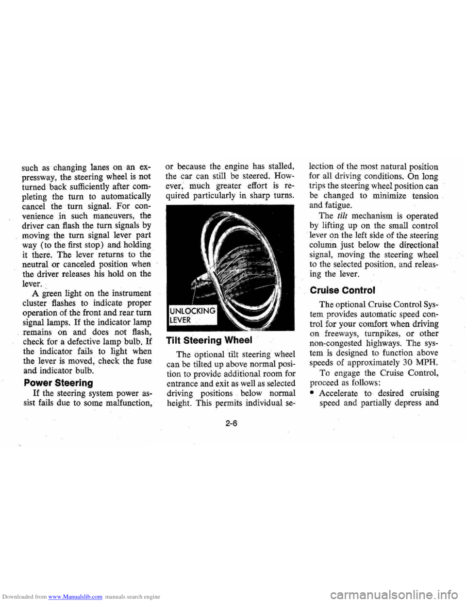
The optional tilt steering wheel
can be tilted up above normal posi
tion to provide additional room for
entrance and exit
as well as selected
driving positions below normal
height. This permits individual
se-
2-6
lection of the most natural position
for all driving conditions.
On long
trips the steering wheel position can
be changed to minimize tension
and fatigue.
The
till mechanism is operated
by lifting up on the small control
lever
on the left side of the steering
column just below the directional
s ignal , moving the steering wheel
to the selected position, and releas
ing the lever.
Cruise Control
The optional Cruise Control Sys
tem provides automatic speed con
trol for your comfort when driving
on freew a
ys, turnpikes, or other
non-congested highways. The
sys
tem is designed to function above
speeds of approximately
30 MPH.
To enga ge the Cr:uise Control,
proceed
as follows:
• Accelerate to desired cruising
speed and partially depress and
Page 21 of 102
Downloaded from www.Manualslib.com manuals search engine release the controlputton at the
e,ndof the turn signallever.
'. ~
• Remove your fool from the ac
celerator pedal and desired speed
will automatically
be maintained . /.
• To change autoIllfltic speed set
ting , press
con.tllol button until
it bottom s and
hold until desired
speed is attain!id.
•
Before releasi~g control button,
hesitate at
th!'!igartially depresse\l
position, th~I},:,remove your foot
from the
ac~,~lerator. If control
button
is IIW t fully depressed,
whenchangi#g speed setting, the
car
will resume your previously
selected
spe~d.
To disengage system, lightly de
press brake
p~al.
, ,.,
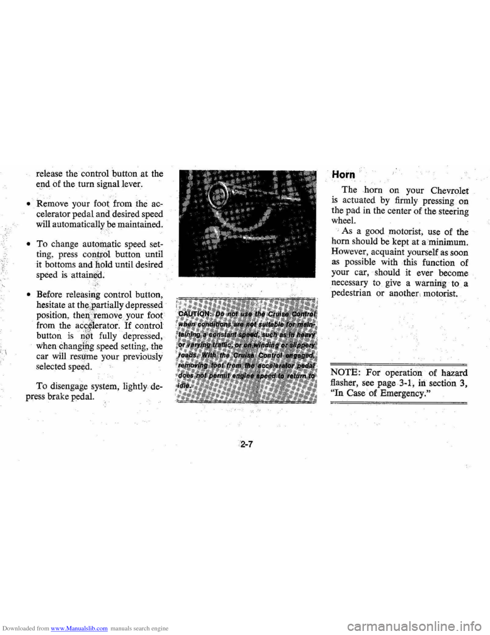
Horn
The .horn on your Chevrolet
is actuated by firmly pressing on
the pad in the center of the steering
wheel.
' As a good motorist, use of the
horn should
be kept at a minimum .
However , acquaint yourself
as soon
as possible with this function of
your car, should it ever become
necessary to give a warning to a
pedestrian or another , motorist.
NOTE: For operation of hazard
flasher, see page .3-1, iii section 3,
"In Case of Emergency."
Page 23 of 102
Downloaded from www.Manualslib.com manuals search engine NOTE: "Riding the brake" by rest
ing your foot on the brake pedal
when not intending to brake can
cause abnormally
high brake tem
peratures, excessive lining wear and
possible damage to the brakes,
in
addition to wasting.gasoline.
Self-AdjustingiBrakes
• Brakes on th(i; ' car (except for ••.
the parking }prake) are self
adjusting, designed to eliminate
periodic
brake adjustments.
• Drum brake adjustment is made
automatically
as the brakes are
applied while car is moving
backwards.
• Disc brake . adjustment is made
automatical1y with each brake
application.
• If excess brakep~dal travel de
velops, drive alternately back-
ward and forward (several
times) and apply brakes firmly
in each direction.
• See )lour dealer if normal pedal
travel is not restored, or if there
is a rapid increase in pedal travel,
which could be a sign of other
brake trouble.
See y6ur dealer also if
adjust
ment of the parking brake is
required;
REMINDER: The front disc
brakes have a built-in wear indica
tor that is designed to make a high
frequency squealing,
or cricket-like
warning sound when the linings are
worn to where replacement
is re
quired. The sound will occur inter
mittently or continuously when
wheels are rolling, but will
dis
appear when the brake pedal is ap-
2-9
plied firmly. See also the various
brake checks listed in the
Chevro
let maintenance schedule folder.
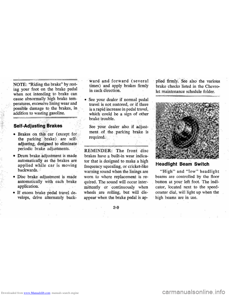
Headlight Beam Switch
"High" and "low" headlight
beams are controlled by the floor
button at your left foot. The
indi
cator, located next to the speed
ometer dial, will light up when the
high beams are in use.
Page 41 of 102
Downloaded from www.Manualslib.com manuals search engine OTHER CONTROLS AND FEATURES
PO$itraction Rea~ Axle
The optional Positraction axle
can provide
additional traction on
snow, ice, mud,
s~d; gravel,etc.
During
normal :4riving and cor
nering, the Positraction unit func
tions as a standard : axle. However ;
when either
drIv&\vheel encounters
a slippery,enoug~urface,the Po;i,
traction can ~i>~~ue to provide
driving force
to.: the wheel havin,g
the greatertr~ction, in,stead of
merely
'" the wheel which
has the least
tra,c:tion.
Power Door Locks
The optionally : available power
door
lo~ks allow you to unlock
, or lock your doors by operating
the switch marked
"LOCK" located
on either door panel. The
auto
matic locking mechanism does not,
at any time, interfere with
mart,ual
operation of any door lock button.
The doors
will not unlock or open
with the inside door handle when
the lock button
is depressed, but
can be unlock .ed individually by
lifting the lock button.
Root~uggag, Carrier
The optionalcarrier allows load
ing of items onto the roof of your
station
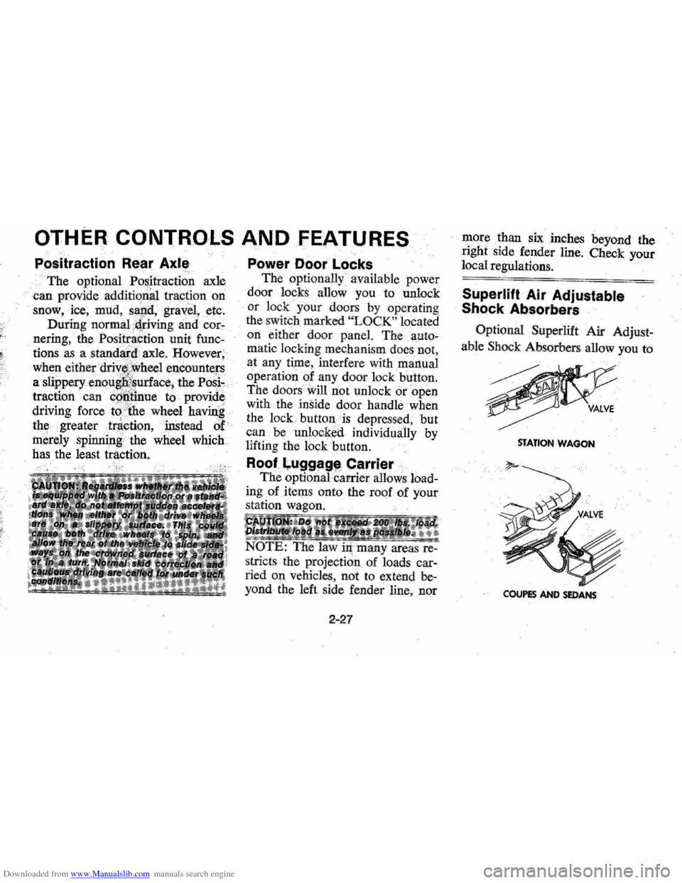
~~~;;;;
stricts the projection of car
ried on vehides, not to extend be
yond the left side fender line, nor
2-27
more than six .inches beyond the
right side fender line. Check your
local regulations.
Superlift Air Adjustable
Shock
Absorbers
Optional Superlift Air Adjust
able Shock Absorbers allow you to
STATIO,.. WAGON
COUPES AND SEDANS
Page 45 of 102
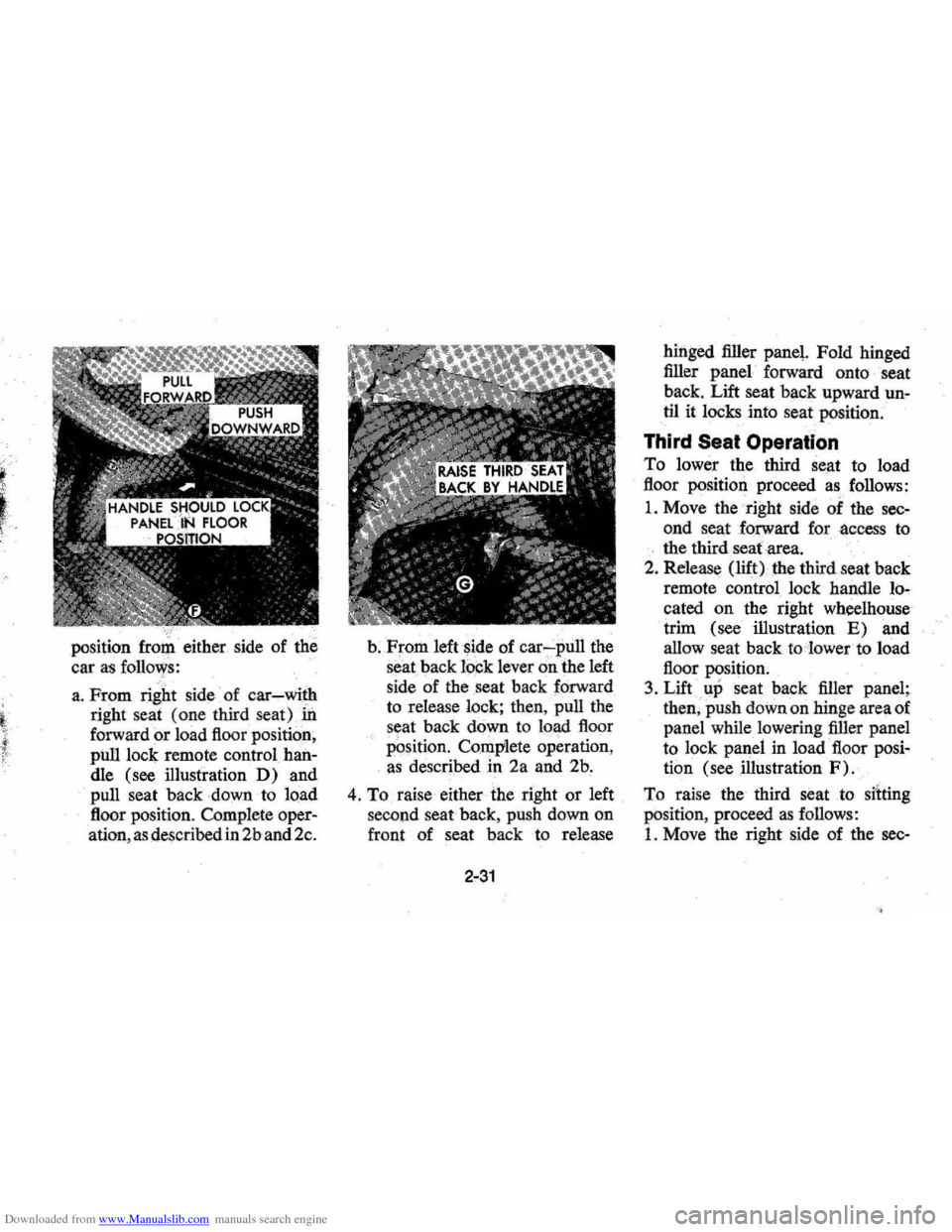
Downloaded from www.Manualslib.com manuals search engine position fro1)1 either side of the
car
as follows:
a . From right side of car~wi~
right seat (one third seat)lfi
forward or load floor position,
pilll lock remote control han
dle (see illustration
D) and
pull seat
baclcdownto load
floor position. Complete oper
ation , as described
in 2b and 2c.
b.From left side of car-:-pull the
seat back lock lever on the left
side of the seat back forward
to release lock;
then,. pull the
s eat back
down to load floor
PQsition. Complete operation,
as described in 2a and 2b.
4. To raise either the right or left
second seat back , push down on
front of seat back to release
2-31
hinged filler panel. Fold hinged
filler panel forward onto seat
back. Lift seat back upward
un~
til it locks into seat position.
Third Seat Operation
To lower the third Seat to load
floor position proceed
as follows:
1. Move the right side of the sec
ond seat forward for ·access to
. the third seafarea .
2. Release (lift) the third . seat back
remote control lock handle lo
cated on the right wheelhouse
trim (see illustration
E) and
allow seat back
to lower to load
floor position.
3. Lift up seat back filler panel;
then , push down on hinge area of
panel while lowering filler panel
to lock panel in load floor posi
tion (see mustration
F).
To raise the third seat to silting
position , proceed as follows:
1. Move the right side of the sec-