Page 16 of 86
Fig. 2
Rear side doors
(inner door handle) 1 - Opening2 - Locking
3 - Access for hand
BOOT (TRUNK) LID (Fig. 3 & 4)
To open: Insert the side door key into lock (1). Unlock and turn the
handle (2), the lid will open slightly. Completely raise the lid and
keep it open by engaging the end ot its stay (3) in the support (4).\
To shut: Withdraw the stay from its support, secure it on the lid
and lower the lid slowly while holding it.
To lock: Use the side door key. With the lid locked, the handle
should turn loosely.
To remove: The boot lid can be removed completely by raising it
to its maximum extent and by sliding it in its hinges towards the left
or right.
Never drive the car with the boot lid open, supported by its stay.
Fig. 3
Boot Lid 1 - Lock
2 - Handle (opening)
Fig. 4
Rear Boot Lid 3 - Stay
4 - Support
Page 35 of 86
MINOR REPAIRS
Headlamp Adjustment
To avoid dazzling oncoming drivers the headlamps should have a
range of between 30 to 50 metres (33 to 55 yards).
Adjustment from inside the car (Fig. 39):
To lower the beams: turn the knob (1) anti-clockwise.
To raise the beams: turn clockwise.
Adjustment from outside the car:
The range and direction of each headlamp can be modified by
operating the hexaganol nut which secures the headlamp to its ball
joint support.
As these adjustments from outside the car can only be carried out
in a workshop containing the necessary checking equipment, have
them done, or checked, by a specialist in these matters.
Fig. 39
Headlamp adjustments
from inside the car (LHD)
1 - Adjusting knob
Fig. 39a
Headlamp adjustments
from inside the car (RHD)
Page 67 of 86

DRIVING
DRIVING POSITION
Seats, Rear-view Mirrors, Seat Belts
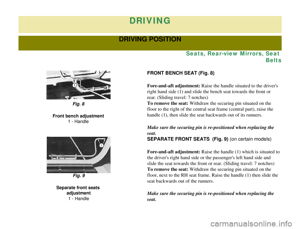
FRONT BENCH SEAT (Fig. 8)
Fore-and-aft adjustment: Raise the handle situated to the driver's
right hand side (1) and slide the bench seat towards the front or
rear. (Sliding travel: 7 notches)
To remove the seat: Withdraw the securing pin situated on the
floor to the right of the central seat frame (central part), raise the\
handle (1), then slide the seat backwards out of its runners.
Make sure the securing pin is re-positioned when replacing the
seat.
Fig. 8
Front bench adjustment 1 - Handle
SEPARATE FRONT SEATS (Fig. 9) (on certain models)
Fore-and-aft adjustment: Raise the handle (1) which is situated to
the driver's right hand side or the passenger's left hand side and
slide the seat towards the front or rear. (Sliding travel: 7 notches)
To remove the seat: Withdraw the securing pin situated on the
floor, next to the RH seat frame. Raise the handle (1) then slide the \
seat backwards out of the runners.
Make sure the securing pin is re-positioned when replacing the
seat.
Fig. 9
Separate front seats adjustment
1 - Handle
Page 68 of 86

REAR BENCH SEAT (Fig. 10)
To remove the seat: Release the rear peg (1) by turning the lever
towards the centre line of the vehicle. Tilt the seat forward to
disengage its lower securing pegs from the floor.
Make sure the securing pegs are re-positioned when replacing the
seat.
Fig. 10
Removal of rear bench seat 1 - Release lever
REAR-VIEW MIRROR
These vehicles are equipped with an interior rear-view mirror and
an exterior one on the driver's side. On "Commercial" versions
(French market vehicles) an additional exterior rear-view mirror
has been fitted on the passenger's side of the car.
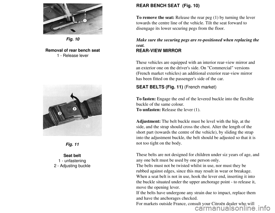
SEAT BELTS (Fig. 11) (French market)
To fasten: Engage the end of the levered buckle into the flexible
buckle of the same colour.
To unfasten: Release the lever (1).
Adjustment: The belt buckle must be level with the hip, at the
side, and the strap should cross the chest. Alter the length of the
short part (towards the centre of the vehicle), by sliding the strap
into the adjustment buckle, the belt should be adjusted so that it is
not too tight on the body.
These belts are not designed for children under siz years of age, and
any one belt must be used by one person only.
The belts must not be twisted whilst in use, nor must they be
rubbed against edges, since this may result in wear or breakage.
When a seat belt is not in use, hook the lever end, inserting it into
the buckle situated under the upper anchorage point - to release it,
move the opening lever.
If the belts have undergone any strain due to impact, replace them
and have the anchorages checked.
For markets outside France, consult your Citroën dealer who will
Fig. 11
Seat belt
1 - unfastening
2 - Adjusting buckle
Page 80 of 86
DRIVING
Comfort
Folding canvas hood
The canvas hood can be fixed in two positions when open: mid-way
or right back above the rear window.
Half-open
Open the hood from the inside of the vehicle but never when in
motion.
Pivot the locking levers (Fig. 24, Mark 1) to release the retaining
hooks. (2)
Raise the front of the hood so as to disengage it completely (Fig.
25).
Pivot the frame (Fig. 25, Mark 1) while pushing the cross-bar (2)
and tip over the frame towards the centre pillar.
Secure the frame (Fig. 26) by means of the strap (1) and press-stud \
(2).
Fig. 24
Opening the front of the hood
1 - Locking lever
2 - Retaining hook
Fig. 26
Opening the front of the hood 1 - Strap
Page 81 of 86
2 - Press-stud
Fig. 25
Opening the front of the hood 1 - Frame
2 - Cross-bar
Fully open
Open out from the outside once the front of the hood has been
opened:
Remove from the tube of the frame (1), the pins (Fig. 27, Mark 2)
attached to the canvas hood, and tip over the frame towards the
front (3).
Secure it by means of the hooks (Fig. 24, Mark 2).
Free the hood securing plate (Fig. 28, Mark 1) from the lugs (2).
Roll up the hood as far as the rear window and fasten it down by
means of the straps (Fig. 29, Mark 1) and press-studs (2).
Fig. 27
Opening the hood completely 1 - Pivoting frame2 - Retaining pins
3 - Tipping over the frame
Fig. 28
Opening the hood completely 1 - Securing plate2 - Lugs
3 - Securing strap Fig. 29
Opening the hood completely 1 - Securing strap2 - Press-stud
3 - Securing plate
[Contents] [Notices] [Important Points] [Driving] [Maintenance] [Minor Repairs] [Miscellaneous Information]
Page 82 of 86
DRIVING
Comfort
Accessories
ASHTRAY (Fig. 30)
To open: Pull on the movable moulding (1).
To empty: Press on the leaf-spring and withdraw the ashtray.
To replace and close: Reverse the sequence.
Fig. 30
Ashtray
1 - Opening direction
INTERIOR LAMP (Fig. 31)
It is located at the top of the Left hand centre pillar and fitted with \
a
built-in switch.
REAR HAMMOCK FOR PARCELS
It is secured between the rear seat and rear window.
It can be removed with the rear seat so as to enable the maximum
capacity of the boot to be used.
MOVABLE REAR FLOOR (on certain models)
Fig. 31
1 - Interior lamp