1974 FORD CAPRI ECU
[x] Cancel search: ECUPage 152 of 205
-
)
Chapter 9 Braking system
,,-
")_'J ,
: ~~ 11111JIII/IIIJ II /I /III Ii hIIllllIlIlIllllIlll 11111#111111 III! -------
8
9
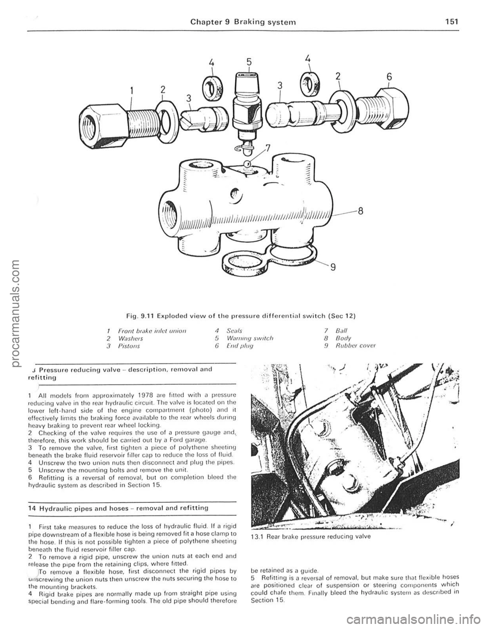
Fig. 9.11 Exploded view o f Iho pressure d ifferenti
J Pressure reducing vulve -description. remalln' nnd refitting
<1 SCi/Is 5 W,If/ll//y $wl(ch (j [lid ilIIIY
All models from ~pproxirniltely 1978 me lilted with il pressure ,educing valve in the rC~f hydraulic Cifelli!. The IInlve is IOCillCd on the lower Icft- hJrHJ side of the engine compn((mcnt (phOIO) ,mel 11 effectively limIts the hrakin\1 force DV
5 Unscrew the mounting bolts ,md remove the unit.
6 Refitting is a reversal of removal, but on completion bleed the
hydraulic system as descrihed in Section 15.
1 4
Hydraulic pipes and hoses -removal and refittin g
7 8.1/1 8 Body 9 R(lb/w( cover
First wke meilsures to reduce the loss 01 hydraulic fluid. If ~ rig id
pipe downstream of a fle~ible hose is being removed fit ~ hose clamp to
the hose . If this is not possible tighten a piece 01 polythene sheetinu
beneath th e livid reservoi r filler cap. 13
.1
Rear brake pressure reducing valve
2 To femove a figid pipe, unscrew the union nutS;]1 each cnd and release the pipe from the retaining ctrps. wh(Jre /riled.
be retained as a gUide.
151
)TO remove 11 fle~ible hose, lirst disconnec t the rigid pipes IN u"screwing the union nuts then unscrew the nuts securing the hose to
the 1l10unting brackets .
4 RiUid brake pipes arc normally made up from straight pipe using special bending <.rnd flare· forming lools. The old pipe should therefore 5
Refitt ing
is J revNsal o f removal, but make sure thJtlle~ible hoses
arc positioned clear of suspension or steering cOlilpo rwnts which
could chafe them. Finally bleed the hydrauhc system as deSCribed in Section 15.
••
procarmanuals.com
Page 156 of 205
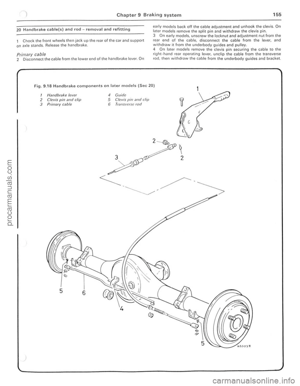
) Chapter 9 Braking syste m 155
20 Hllndbrake ctlble(s) and rod -removal and refitting
I Chock the hon wheels Ihen jack up Ihe rea, ollhe car and support on a~le stands. Release tho handbfilke .
p,imary cable 2 Disconnect \heCllble flom Ihe lower end of Ihe handbrilke lever. On
c1'IIIy mOdels back 011 the cable ad,ustment and unhook the clevis . On latcr models remove the split pin and withdraw the clevis pin. 3 On early models, unscrew the locknut and adjustme nt nut hom the rOlll end 01 Ihe cable. disconnect the cable Irom Ihe lever, and withdraw it Irom the underbody guides and pulley.
4 On l
•
I HaN/brake lever 2 Clevis pin lIml chi) 3 Prif!!lIfY clIble
4 Gllidc 5 Clevis {lin illld r:hiJ 6 TWf/sveISC lOti
3
, , ,
, '. , /
·f
! I i ,
I:
!
1 1
i 1·
!
j j
procarmanuals.com
Page 157 of 205
,
156 Chapter 9 Brakin g syste m
Secondary cc1ble (early models) 5 Loosen 1I1c lock.nut ~nd unscrew the adju stment ferrule from the right-hand rear clevis.
6 Remove the split pin and clevis pin securing the secanda.v caulo \0 the left-hand Icar operating le ve l. 7 htrac the clip, remove the clovis pin. and withdraw the pullcy wheel from the lever on the Ical a~le. 8 Remove Ihe cable from the lever.
Transverse rod (later models) 9 Disconne ct the cable from the righi-hand rear opCfating Icvcr by
removing the split pin and clovis pin. to Uncl.p the cable hom the 'Hlnsvcrse rod . 11 Remove Iho spli, pin and clevis pin securing the fod 10 the Icft·h~nd le;!1 operating lever . 12 Slide the transverse rod Irom the guide on the rOM axle . 13 Check thO {luide bush lor wear and dama ge and renew It il necessary by prising il oul and pressing a new bush irllo POSilioll.
All models 14 Refining is a r e versa' of removal. but lubr icllto the lin kage as )scflhed in Section 2, and atljl' stthe cable as (fescri bed in Section 18.
21 VilCUUrll sorvo unit -dosCrilHion
A vacuum servo unit is linod Into the lir,lk e hydrallirc cil cu il. 111 series with I he 111,1S ler cylinde f. to provide assiswnco to the dllver whlln Ihe brake pedal is depressed . Thi s reduces the eHolI le{luired try the driller to oper,lIe the brakes, under all brak ing condi tions .
This unit operates by vacuum, obtained from Ihe indu ction mnni rold and comprises basicall y iI booster diilphragnl and check lIallle . The servo unit and hydraulic master cylinder are connected
t o gether so that th e serllO unit piston rod acts as the master cylrnder pUShrod. The driller's b rilking ellon is trilnsmitted through allot her PIi ShlOd 10 the serllO unit piston and ils built-in COmrol system . The scrllo unll pislon docs not fit tightly inro the cylinder. but has a strong ,lltl flhril!Jlllto ke el) liS edges in COllst ilnt COntaCI with I he cylinder Willi_
23 rilult diagnosis -hrilking system
~ylllptom
-'ceSSllle ped,,1 u;tllel
nrakcs pull 10 ono Side
Or;tke ludder
E~cessive eHor l to stop car
so ensuring an i1inigh t seal between the two parts, The fo rward
chamber is held undelllaCUUm condi tions cleilted in the inle t manifold of the engine and during periods when the brake pedill is not in use, the controls open a passtlge 10 the rear ch ambe ., so placing it under lIacuum conditions as well. When the b.ake pedal is dep.essed. the lIacuum pass.Jge to the rear chamber is CUI oH and the chamber expos ed to atmospheric pressure. The consequent rush 01 ail pushes
the servo piston lorward in tile lIacuum chamber and operates the main push rod to the m.Jster cylindcl. The controls are designed so that assistance is given under all condllions. When the brakes are 1'101 requ ired, vacuum in the rear chamuer i s .e -es tabl ished when the br.Jke ped.J1 is released . All air Irom the atmosphe.e entering tho rear ch.Jmbe. is passed through II sma ll air trlter. Und er normal opcr.Jting cond itions tho IIflC(IUm serllO unit is lIery relraule and does not require ollerhaul e~cepl at IIcry high mile,1geS. In this case it is far bcner 1 0 o bta in a serllice e~hange uni l. r,1the, than rcp;ti . the o,igi'lo11 unit . Although inlernal components we,e once .Jv'lIlaule 10 ' ovcrhauling purposes this service has no w been
d,scont,nue(t .
22 Vacuulll servo unit _ remOlla l MId re filtillg
I RemOIlO the master cylinder as desc.ihed In Section 10. 2 D,scolllwc l thc vacuum hose from the non·return lIalve on the serllo \lI1it. 3 Work i,,!) insido thc cal. remOlle th e lower l;t cia panel below the stccring column. 4 E~tractlhc clip and l)ul1 outlho clellis pin attaching Ihe push.od to the l ootu .ake ped;t!. 5 Unsc.ew the nuts securing thc mount ing b.ack.et to the bulkhead.
then withdraw thc serllo unit and bracket from the engine COlllp,lJtlnen t, 6 UnSClew th e nuts ar1(1 serlar,lle the braket 110m the SCIIIO uni, . 7 netrning IS;t rell e.sal 0 1 remOllal w ith leference .Jlso 10 Section 1 0 when retrumg Ihe master cylrnder.
Renson(s)
RC.Jr blake self adju sting mechanism faulty All i n hydrilulic system
WOIll or cont,llllina led /rnin{Js Seized Caliper or wheel cy linde r
E~cessille run-out or distortion of discs o. drums
Worn Of cont aminated linings Brake backplate or caliper l oose WOIll suspensio n bailloints
SerllO unit faulty
Worn or conwmin.Jted linings
I
J
procarmanuals.com
Page 162 of 205

Chapter 10 Suspension and steering 161
fig. 10.11 Drivebelt [ldjustlllent pulley holts on 3.0 litre models -arrowed (Sec 2)
2 Routine maintenance
At the "*',vals spec ,f,ed III the Routine MainhHlance $()(;t,on in the front of til() manunl c,lIIy out the 101l0wlIl\j p,o(;cdures.
Check lyres for illflalioll, wear and conditioll 1 Check [lnd If necessary adjust the tyre pressures .
2 Check [III t yres for WC[lr and condition with referenc e to Section 21
Check power steering pump drive belt tensiof) 3 Check thm the deflection of the drivebelt m,dway ulon!) its lonyest nlll between upper pulleys is approxirn
(photo).
Clwck puwer steering fluid levef (lnd hydraulic huses II pOSStble the level should be checked w,th the Buid [It nOll1lal
uper,\!mg tClIll)Cr[lture . 6 On c;lrly modcls unscrcw the wing nut nnd relnove Ihe rese,voir cover ilild uaskel. The flu,d should be up 10 Ihe MAX level mark on the
reservo". 7 On later models, wrn tht! hiler C
Fig. 10. 5 Topping·up the power steering reservoir on early models (Sec 2)
8 Whele nec.ess.1'y ~dd Ihe ~pccilled lIU1d to bring Ihe level up to the
correct ,nilrk. 9 ChC(;k the hydr[luhc hoses for comJit,on and security.
Check steerinfj ,-md suspension components 10 n,ll$O tilt) front ilno reM 01 the Cill or position over an inspeclion pn. 11 Check the SleetinlJ wck and t'e 'rods for d[lm3ge und weM. Also check the wek HJbber bellows and track rod end rubber bOOIS for spfilS
ilnd leilk[lge. 12 Chec k the front ,md reilr suspension components lor d"m.Jge [lnd wear. In particuf;lr check the front suspension tr.Jck control Mm ilrod stahiliwr r"bber mounling bushes. Usc a lever to check that there is no excessive we[lr III the Iron I slispenSlon lower IJ[ll lJoints which Me
"'\()\JIill wnh the track conlrol ilflllS . 13 Check the operat,on of the I,ont ;IIHt rear shock absorbers This is
be st ilchievcd with thO} Cilr on the \lfOlind by depressing euch corner of the ca' 1111\I1. On 'ele[lsil\ljthe C()"H~r helllU checked Ihe body should ,,~c thell s"llie IIlIl11ed,mely on ,t~ way down. II there nrc sever.J1 ()sclll;ot'ons the sho(;k absorber IS weilk nnd should be renewed.
3 Front hub _ removal. refitliny and bearing adjustillent
Apply the h[llldhr[lke then Jilek tip the front 01 the cm ilnd support
on axlt! standS Remove til(! rOildwhecl 2 Rernove the front ul;lke CJllper With ,elerence 10 Ch.Jpter 9. Whele the flex,ble br[lke host! is connecte(t dueclly to the cililper ther e IS no need 10 disconnect the hose i1S thO} caliper can be suspcnded by wire
aWily from the diSC. 3 By calelul 1
" :<>,:,~,.
Adjusting the power Sleering pump drivebelt tension on the 2.8 litre engine
2.7 Powcr steeling filler c.Jp/d,pstlck for the 2.8 hIre engine
3.3 Removing the dUSI cap from the front
hob
i
i ,
~ !
procarmanuals.com
Page 163 of 205

162 Chapte r 10 S uspension and steering
)
Fin· 10.6 Front
@",.,i
, 5
Y 6
hub cOnll)oncnts (Sec 3)
12
1 0,1 seal 7 Diller be,?li/!{J Iwck 2 IIIlIcr bcaring wee 8 GUiN Iwmitlfl filct' 3 Inner bemiJlg /I,?ck 9 ThlllS! wilslwf 4 Screw 10 NIII 5 Disc 11 Sf"il (lin 6 H", 12 01151 C.1jJ
4 Remove the split pin frorn the nul rC\;linCf and undo the adluS\ing nul from the stub a xle. 5 Wilhd,nw the thr ust washer and the outer tapered he,..ing. 6 Pull off the complete hub ;111(1 disc ilsscrnbly ffOIl11hc s tuh tlXlc. 7 To refit locale the huh tlSscmb ly on the stub il~lc <'Ind slide on the outer hc"rinu nnd II1
1 0 Rei" the nut ret;)u)Cr SO th~t the spill pUl holes ~re ~lIg"ed. Fit a
v split pin
2 Cmelully prise out the gre.lse senl Irom the b~ck 01 the hub
Scoop out the grease 110m inside the huh imd wash clea". S Drive the new bearing tr
glease well into th e beiu ings. lully p
Front Suspension strut _ renl0v
Apply the handbrake then jack up the Iro"t of thc car ilnd SuppOrt r ViC S\Jnds, Remove the roadwheel.
.lel1love th e front hub with referen ce to Sec lion 3,
56 Front SllSI',,"~'nll Slrut uppe, moullt"l{j
5.7 Lowellnl) 110" f'o"l SUSrlt''' S'OIl ~lr"tlro"'ll"der the wheel a,ch
I !:'~
!; ... ~
-;;
3 On e~rly n,,,dds. Icmove the "\lI d brake p'pu ""d dew ch Ihe flex'hle hose 1,0 '" the br.1ckct on thu strut (, f neccssilry ruler to Ch"p ll'r 9 ).
4 OlsconneClilHlu.u:k rod l'nd from the steer;ou n'm (Sect ion 14) 5 Extrncllhl' spirt p,,'
tool.
6 Workrng Ul1d'; r Ihe bonnet. un screw the three mounting nuts sec(Jl iog the 51'Ul 10 the wheel arCh (photo). Where applicable note the location 0 1 Ihe ilce ele r" tor cnble Slipporl bracket be ne3th one of the
nulS .
7 Lower the stru t ~ssembly from undl'r the wheel arch (photo).
8 Refll,!n\) '5 i' reve rsal 01 removal. hut ti\)htcn all nuts 10 Ihe
specified torq(,e fl"fe r 10 Section s 14 and 3 as necessary.
6 F ront coil sp ring - removal and refitting
Note: In Off"" /0 ,(:mo ve Ihe corl .~"{!finy ffOIl! the strut it writ be neccssa,y /0 ub/."" .1 sui/able sP"".
Page 164 of 205
Chapter 10 S uspension and steering 163
~~--,,$iJO
~~\~
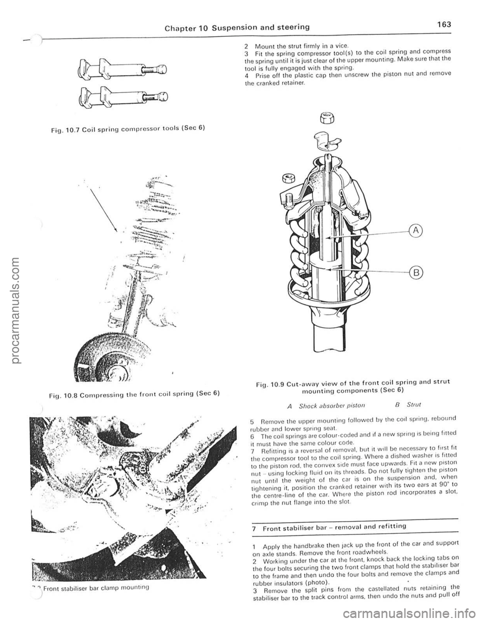
Fig. 10.7 Coil spri n g compressor lOo ls (Sec 6 )
\.
FiU. 1 0 .8 C o rn pressi nu the frOllt Goil spring ( S ec 6)
~ " / ron t stobiliser bar clamp mountrng
2 Mount the strut firmly i n ~ vice .
3 Fit t he spring compressor tool(s) to the coil spring and compress the spring until it is juSt clear of the upper mounting. Milke sure tho t the
1001 is f ully engilged with the spring.
4 Prise off Ihe plastic cap then unscrew Ihe pis ton nut ~nd remove
t he cranked
retoiner .
F ig . 10 .9 CU\·
ilWilY view o f th e front coil spring nnd strut mountin g compo nents (Sec 6)
A Shack absorbfN pis/ull B 51,,11
5 Remove Ihe upper 1110unling lollowed by Ihe corl spring. rebOllnd
rubber and lowe r sprrnU seal. G The coil springs are colour· coded ,1nd II a new sprong 's being I,!led
il muSI hilve the same colour code.
7 Ref itting is a reve,sal 01 removal. but il Will be neceSS
lhe centre.line of Ihe CM. Where the p iSlon rod incorpor
II~nge into the 5101
7 F ront stabiliser bar -removal
he hand brake then Jack up the front of the car and supporl
on axle stands. Remove Ihe fronl roadwheels.
2 Working under Ihe CM at the Irani. knock back the loc king tabS on the four baits securing tile two f,ont ct~mps Iha t hold the swb,hser ba r
t o the frame and then undo t he four bol tS and remove lhe clampS
,
I " I , ,
j
!
procarmanuals.com
Page 165 of 205
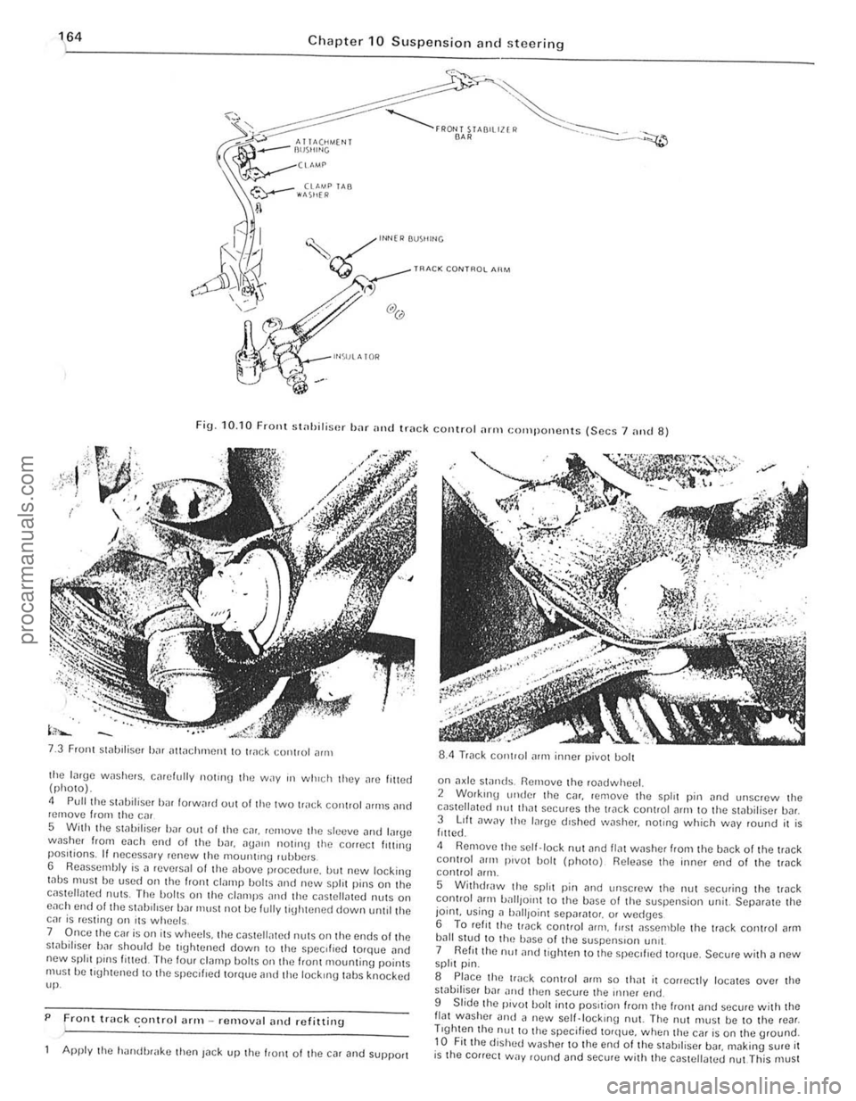
Chapter 10 Suspension and steering
~ l"Nfl> BUS"'''G
~ TRACK CONT~O~ AIIM
Fig. 10. 10 FrOllt st
Front Slilblliser bJr iltlilchmCIll to tr
5 With the stilbiliscr bilr out of tire Cilr. rernovtl the sltltlve Jlld lilrge wnsher from each end 01 the bar.
7 Once the car is on its wheels. the c(lsteli,lted nUlS on Ihe ends olthe st,)bifiser bar should be tl\[htened down to the specIfIed torqlJe .. nd new spill pinS filled The four cl(lmp bOilS on the IranI mountinu poinlS must he tluhtened 10 the specliled torque and tile lockIng whs knocked up.
P
Front truck conlro l ;lrm -removal alld refitting .
Apply the h'lIldl.>r
on a~le swnds. Remove the roadwheel. 2 Working ullde! the C(lr. remove the spirt pin (lnd unscrew Ihe cilslellmed 11111 Ih"t secures the trilck coniroi
5 WithdrJw the split pin [lnd Ullscrew the nut securing the trilck control Jflll battlOIl1 10 the base 01 the suspension unit. SCpar[lte the joint. using n ball,oinl Sepnr[llo,. or wed(Jcs 6 To ret, I thc lI"ck conlrol arm . fllsl JsscOlble the track conlrol [lrm bJIl stud to Ih(~ bilse of the suspenSIon !m't 7 Reflllhe nu! ilnd tighten to the speCIfIed torque. Secure with a new spirt pin.
S Place the track control (lrill so IhJt il conectly locates over the sliIbiliser hJr nltd then secure the iIlller end.
9 Slide Ihe pivot bolt into pOSItion "0111 the "onl and sccure w ith Ihe flat washer Dud il new scll.lock,no nut. The nut must be to the rear . Trghten the nUl to Ihe specified torque. when thu car is on the ground. to Fit the dished washer to the end of the stabll iscr bDr. making sure it is the cOllect way round and secure wit h the cas tellated nut This must
-------------------------.. procarmanuals.com
Page 168 of 205
) Chapter 10 Susp e nsion an d steerin g 167
• ____ I,,, .. r,,,.,
.. , ..
"""""
/
..... . '''M'
""'''''' . ..... >'< '.' AU ... , ..... • Ut ~" ... '''toI •• " .. (', @
........ ' ........ -~~ ' • • ~Mr
.,,·,"'·'·,v"""" ".$"'" ''''.''''.",,~. ~
."', ~
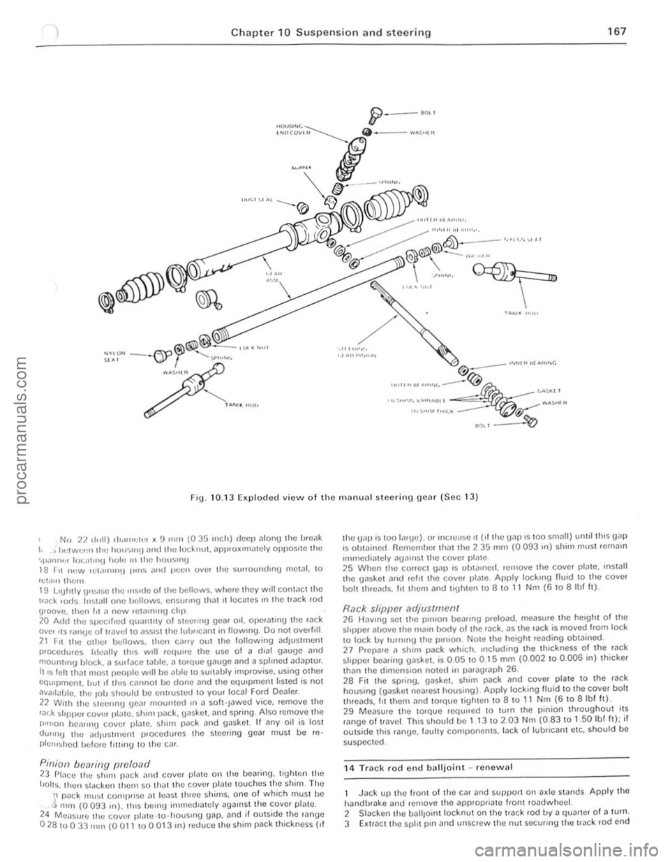
F ig. 10. 13 Ellplodcd view o f the IlHII HHl I steering gear (Soc 13)
No 7.7. d"lI) ''''''''':1\:1 )( !) nit" (035 Inch) deep
22 Wllh the ~Ieelmg Ueilr mountud III iI so h·Jawcd yice. remoye the r,:u:k ~I'ppur coy", pl!!Ie. shim p,1ck. {lilskor. mid sprIng . Also "Jmoye the I"n'on bOilflll\J coyer plalC. sh im pac k and gaskot. It i1ny oil is lost dUIIIl!) thc adJustfllenl procedures thO steering gea r must be rl!'
plc'''~hcd hclore IllIIng to Iho cm.
P,niOIl bec1ring preload 23 PlilCC the shun p,l c k alld covcr pl1lle 011 Ihe bearinU. lighten the 'JOlts. then s lacken Ihcm 50 .hal Ihe covel platc louches the shim The \' pilck Illll~t (;omj}lIs e ill hlil st three sh ims. one 01 which musl bc Q m,n (0 093 In). tlus bern!) ullllledlalely agaIns t the COYcr plate. 24 Measure Ihl! COV'" pl,lle .to·housllIg gilp. and if outside I he ranUe 02810033 fllill (0 all 10 a 013 In) reduce 'he shim pack th ic kness {If
Ihe UilP is '00 li1rud. or Illcrei lse II ("the gap IS 100 slllilll) unlll Ihls gill) IS Ob'ilillcd Remembe r Ihat lhc 2 35 111m (0 093 III) shim Illustrcmillll
Immcdiately "UilIllSt Ihe cover pl;)'e 25 When the COIICCt \1.11) IS ohl!!lIlcd. rernoye Ihc coy!;'. pl"le. IlIs!.111 thc gasket ilild r efit ,ho coyer ,)IJ tc. Am)ly locklllg lIuid 10 Ihe coyer hOi' th.eilds. lit Ihem ;)"d lighlen,o a 10 11 N m (6 \0 albf It).
Rack sl/iJpcr .1djus(mell( 26 HilYlllg set thO pOlllon bearing preloJd. measure 'he heIght 01 the stopper il!J.OYC the IIIillll body 0 1 the rJck. as ,he rilck is moyed Irom lock \0 lock by turnIng 'he pillion NOIe thc height reilding obtained. 27 Pr CPilre ;l shim pack w hiCh. Including the thickness 01 the 'ilck sloppe r beJring {JilslIet. is 0.05 to 0 15 mill (0.002 10 0 .006 in) thicker than ,he dimcnSlo n lIoted In piuagrilph 26. 2a FII Ihe spring. gas ke t. shim pilck and coyel plate to 'h e ra ck housing (gaske l ncareSt housing) Apply locking lIuid 10 the coyer bolt thrcads. III them illld 10rque tigh.e n to 8 10 11 Nm (6 to 8 Ibl h). 29 Measur e thc ,orque rC(tullcd \0 lurn Ihe p inion throughout i,s mnge of I!.lY cl. ThiS should bc 1 t 3 10 2.03 Nm (0.83 to 1.50 Ibl It); if oulside th,s ,ange. Iilul,y componcnts. lack ollubriCilnt etc. should be
suspected.
1 4
Track rocl end balljo int -renew al
Jack up thc loon. Of thO Cil r and SUf)pOrt on Jx le stands Apply the halldbrilke ;)nd re!llove Ihe applopriil'C Iiont roadwhcel. 2 Slacken Ihe baliJo in l locknut 011 the track rod by iI quarter 01 a turn. 3 Extra ct the spl, t p,n Jnd unscrew thc nul securrng the !Jilc k .od ond
, .. • • ..
::
procarmanuals.com