1974 FORD CAPRI ECU
[x] Cancel search: ECUPage 131 of 205

130 Chapte r 7 Pro pelle r sh aft
14
. 12 ~
"> ., I>
" 10 11
9 a
·6)6f
. -r 3
~I"")~ 2
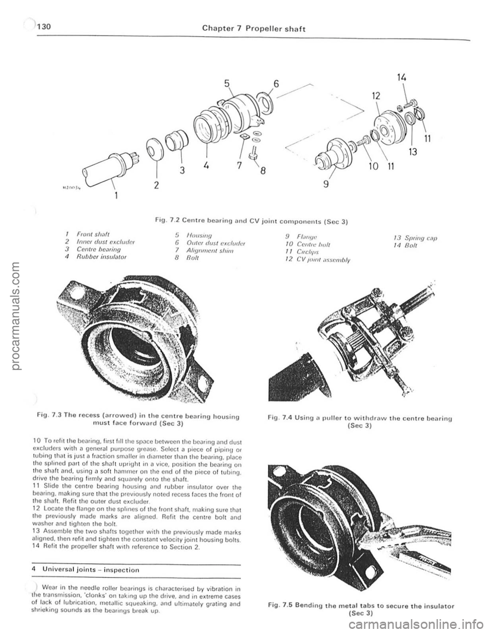
Fig. 7 .2 CCllIre bearing and CV joint cOIll I)onenls (Sec 3)
1 FIO,,/ sll,1// 2 Inncr (/(IS/ cJ(cfudm 3 Cemrc bC.1riny 11 Rubber in$u/.l/(J'
5 1f00wl/f/ 6 Du/!)( rlusl cXl;/mh'I 7 AIlYflml'lJ/ shim 8 flull
FiU · 7.3 T ho recess (;ufo\l\lcd) in the <:orllre bearing housing m ust la ce forw(.rd (Soc J)
10 To lI~fll the bearing. first f,lI the 51)
alrgned. Ihen refit and tighten the constanillclocity joint housing bolts. 14 Refit the propeUef shalt With ,efefcnce to Section 2.
4 U nillorsal joints in sp ectio n
) Weaf in the
needle rollef heafings is Ch,Uoclefi sed by vibfalion in the tfan srnission. 'clonks' on takrng up the drille. and in e~treme cases 01 tack 0 1 lubficat ion. mOlalhc squoaking. and ultimately grating and
shrie king sounds as the bOilflngs breiJk up.
9 Fl.",!!.: /0 C('/IIf<.' 1",11 /1 Cllcllf'S 12 CV /01111 ilssl:mbly
13 Sprillg c.lf' 14 Boll
Fig. 7.4 Using.~ plillor 10 withdraw the centre bClI ring (Sec 3)
Fig. 7.5 Bendi" g the metal tabs to secure the insulator (Sec 3)
procarmanuals.com
Page 135 of 205

1
134 Chapte r 8 Rea r axl e
FiO. 8.5 Discorlllccti!l9 the rcar sI"biliser Iwr (Sec 3)
7 U~"'!I u"ps (FlU 8 5) I)UU rile s1.1h,l,s(lI b.ll 10 lilt:! lCol. while unstocwIIlIJ the mOlllllnlU I)oIIS from the Ie;)' ;l~II!. flcl110vc the C!JIllI'S 8 W,lh the rC:II Ildc sUlt,lbly SUIlI>o.ICd. lIIlSCICW rhe nulS hom the hallom 01 the U-bolts i1rld reOlOlle rhe lowel S I)llrlU p l;lrcs .. ",t! 1115 .. 1<11015. 9 Wllh rhe help of an asslSlilnt. hft the rem a~lc over the "~
Chock Ihe front wheels then jack up the re,lr of the c~r ilnd support with onle stilnds. Remove the .ear wheel 2 Ilelea se the hilndb.nke and .emove Ihe brake drum.
3 USIng a socket through the special holes in the drive lI.::tnge. unsc'ew the bollS secu.ing the b.::tckp late and bearing ,el.::tinor to tho a~le cilSln g (pholo). 11 Withdraw tho a~leshnft. together with the bearing. " it is tight due 10 tho oulor Ir
ig. 8
.6 RelHoving t h o Mdeshalt .e l'l ining hoits (Soc 4)
If
I
/1
II
I
\,
Fig 8 .7 U sing long bolls to ""ithdra"" tho a~leshaft (Sec 4)
cd
procarmanuals.com
Page 136 of 205

m
)
Chapter 8 Rear axle 135
Fig 8 .8 Drilling the beMing rf!t
5 AxlcshiJft homing -renewal
Noto: A SfJL'CI.1f 1001 IS "Hlliller! /0 n'III1:''''''[1 (,0111 lilt' axles/mIl (s,:c Fly 89) 1 Remove the ;,xlushalt as ,h:sG"hcd 1(' St;CIl0n 1 2 Usin\J all 8 mill (0.31 In) dldl, 1Il;,kc a hole III the he,Hlnt! ,etauun\1 119 . t
G Cleiln the l1xlcshnf1. be,non\) ,,,t;WlC' ,Hld "xle C.,1511l\) 7 Locl1le the loe1ll1ll9 HIWlIlel 011 the l1xleshl1lt. followed uy tho new uoa,ing wIth the 001 sel1l [l1CIll\) l1WilY ['om the l1~leshaft Hallge. 8 Slide on the new hea'lIl\) rcta"lIn\) '1119 and pr ess J fully 11\l111l1st tile hearing inner IWck. uSIng a slJItJIJle puller or J ICWlth oftuue. 9 Re fIt Ihe l1xleshalt wllh refe'ence to S ectIon <1
6 Axle reM cover relllov,,1 ilnd refitting
Chock the hont wheels then lilck up the re,l( o f the Cl1r il'l(l SOPPOI1 on axle stands.
2 Cl em1 the reM cover .Jnd surroundIng .Jre" (photo) 3 Remove the hllmlbr"ke relay le ver lind seco nd.Jry cable. or
transverse ,od (as ;;Jpplicilblc) with reletCnce to Ch"pter 9. <1 Place a suitable container helle~th the reM "x Ie to c~tch the oil as the rear cover is removed.
5 Undo and remove t he ten IJOlt s and sprinU washers lhilt securo the reill cover to the llIl,l l drive housillg LIlt aWilY th e re"r cover and its
\Jasko!. ~ Before refitting the ,oar cover Illilke sure thm the mating fJces ilre free of th() old Uaskct or 10nlting compound.
7 FIt a new uasket Jnd then the lea, cover and secure wIth the ten bolts and spring washers. The cover bolts protrude IntO the fillal drive hOUSor1U so it is important that a SUlwble oll·resist.Jr1t scaling
... __ ro*
Fig. 8.9 Usill(J the special Ford tool to removc the axlesllilfl henring (Sec 5)
r;olllpoulid IS SlIll:ilr() d onto lioe Ihro,'ds of each boll bef ore it IS [,twd. 8 TIUhwll tllr: cover secu,,"!.! holls 10 lhe spec,[,ed torque Wfl:IICh
se ttln\)
9 ReCOlillect
Iht! h,lndbr,l~e components with re ference to ChJp ter 9. 10 R efil l ti,e 1e;1I ,ule with the correct 9rJde 01 oil then lower the C,lr to
the UIOUIl(i
G
2 Axle reM cover
7
Pinion oil seal -re"cw,,1
This ope r,ltion may be performed WIth the rear axle in position or on
the benc h
2 Undo ~nd remove the two holts. sprinU Jlld plain washers that secure lhe centre bearing support to the under51(fe of the body (reler to
Chapter 7) 3 With a sc"ber 0' fde. Ill
propeller sha h to ttt() flool I I
J m
procarmanuals.com
Page 137 of 205

Chapter 8 Rear axle 136 )
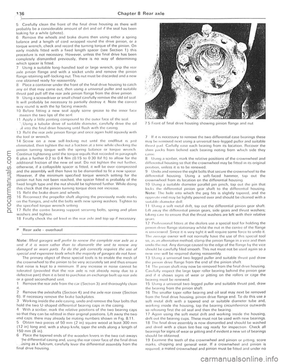
5 C~rellJlly cle~n Ihe Ir Oll 1 01 the Im,ll d"ve housinU ~s there will Ilroll
P ReM axle -o verh;;lul
Note: Mosl ymilycs wtlf Ilft'h" 10 If.'IWW Iflt' comfllelC IC,ll ,Jxfc ,15 .1 111111 d II IS WOII! ,.II/IC' I/Ioll! 10 rf,SllliI",fc Ille UII/I 10 lel/t·w '''IV r/;/11I.Jycd 01 WOIII poll Is ro do tlw ,ob correclly Icquires Ifle usc 01 spccial <111(1 cxpellsive loofs willch tin' "'",u/lly of y"WY"'S do 1/01 h,lVl' The P"n1
,' . 2 Remove the a xlesh;;lhs (Sec lIon 4) "nd the;lxle ,e". covel (Secllon 6) . If rleceSS;;Jry remove lire !H" ke !liIckpl;,ws 3 WOlk,n!) inside IIlI! axle casUlU . undo .lnd .emove Ihe four bolts th" t hold Ihe IWO U'Shill>cd dlllerentl,ll be"rmg CilPS III the Cilsing. 4 W,lh a sc.iber. m
15 Froni I'll Im
",.IY I,,, ",move(1 Ih:xl uSlnU " ulllvers,,1 two·leuged puliCI and sui!
NOLI! : 1 hu h"le 11110 willch thc peu Irts IS shghlly "'I>c.ed. lind the I>pl''''.'I'! "",1 may he IrIJhLly peelH)d over ;'Iml should he r.:!e;rned with a ·.u,I.II,I" ,".11111;1". ,tr,ll 11 th'''!1 a ... "It IIlI;t.11 dllfl. "'i> out Ihe drllelenli"l p"uon Ue", slr"h. 1.011 .Iw.ly tlr" d,lh;u!Oltl;r1 pinian ue,us. sido {leMS "lid IhruSI was hers; IA"'!l':,"" 10 ell::ure Ih"t the th,usl washe.s ",e lell wllh Ihe ir relative
liP,"" 12 1'",1"~"If)f .. ,1 Il1te.s (It Ihe
procarmanuals.com
Page 140 of 205

•
Chapter 8 Rear axle 139
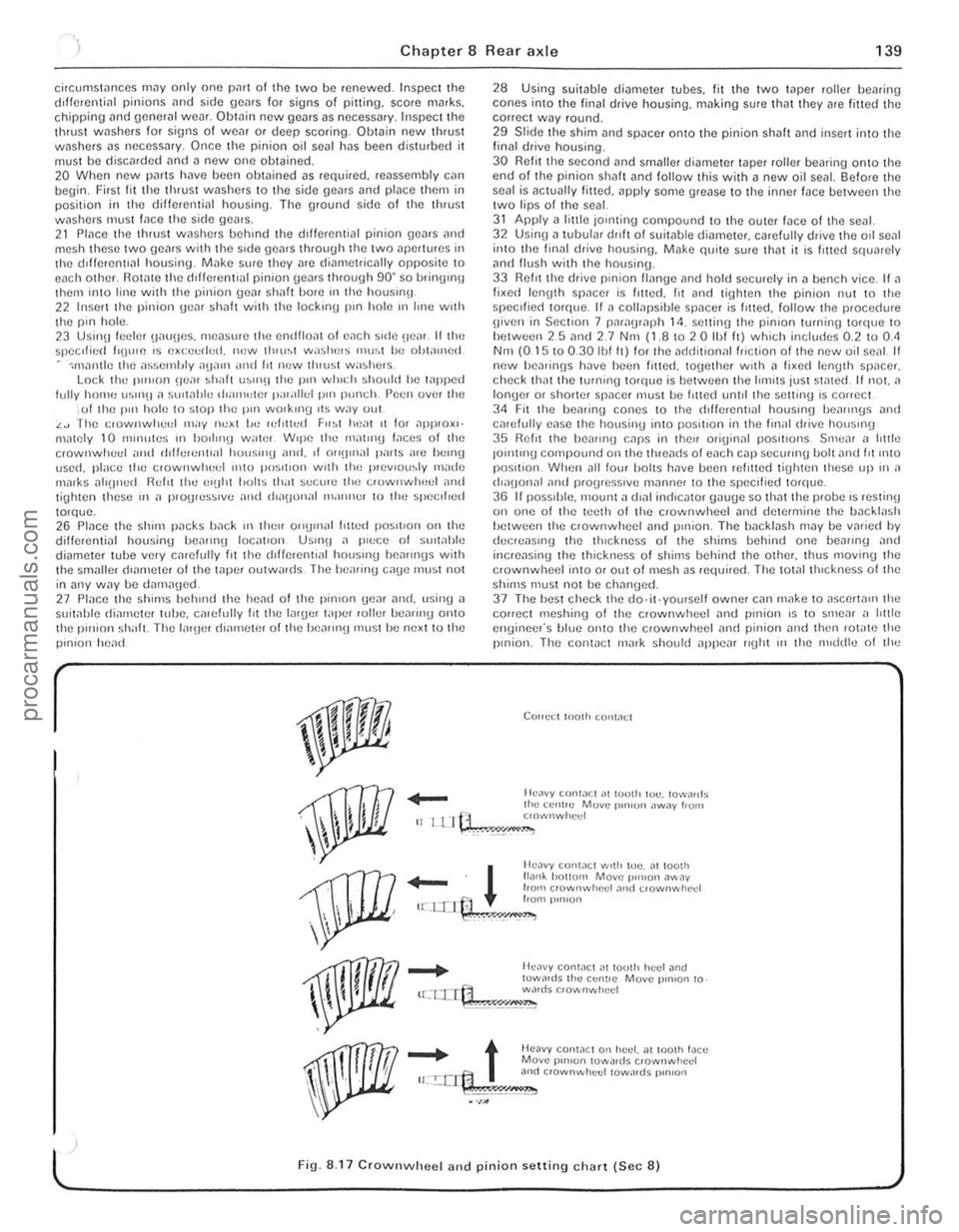
ci,cumS«"Ulces mny only one pmt of the two be renewed. fnspect the dllfe,enti,ll pinions nnd side gems for signs of pitting. score mMks. Chipping nnd general wem. Obtain new gears as necessa,y . Inspect the th,ust washers lor signs of weM or deep sco,ing. Obwin new thrust wnshe,s as necessary. Once the pinion o il senl has been disturbed it must be discMded and a new one obtained. 20 When new pnrts have been obwined ns required. reassembly cnn begin. First lit the thrust washers to the side gems and place them in position in the differential housing. The ground side of the thrust washers IllUSt lace the side gC.Jrs. 21 Place tile thrust wilshers behind the dillelentini pinion genrs i1nd mesh these twO Oems with the Side gears through the tWI) ilpertores in the lilllerentlill housing. Milke sure they ilre diametlicilily opposite 10 each other. RO«l!e the clillerent'i11 pinion gears through 90' so brinUlI1\j them into line with the pinion genr shnlt bore 111 the housinlt 22 Insert the pinion genr shnft with the lock In!) p'n hole III line with the pill hole. 23 Usinu leeler 1),IU!Jcs. measure the en{lll(",t 01 ench s,de Be,,,. II the speclficd h\Jure IS excecrt"d. IU!W tl"u~t washlllS mu"t he olJt,uned
-omnlllie the a~~el)lhly ,lg,llll ,trld ht new thll,st wa:,lu'
28 Using soitable diameter tubes. fit the two Wper roller bearing cones into the finnl dlive housing. making sure that they ale litted the correct way round. 29 Slide the shim and spncer onlO the pinion shalt and insert inlo t he final drive housing. 30 Relit the second and smaller diameter wper loller bea,ino onto the end of the pinion shaft lind 101i0w Ihis Wilh a new oil seal. Sefore Ihe senl is nctually fitted. apply some grense to the inner Ince between the two lips of the seal. 31 Apply n little jOinting compoond to the outer Ince of the seD I. 32 Using n tuhulilr dllft 01 suitable dinmeter, carefully drive the oil seal into the fillal (hive housinlJ. Make quite sore thnt it is lilted squarely and flush with the housinU. 33 Refn the drive pinion IInnge nnd hold securely in n bench vice. It II fixed lenIJth spncCl is Itlted. fit ilnd tighten the pinion nut 10 the spec ,lied lorque. If a collapsihle spnce r is f,tte d. follow the prOCedlHe
g iven in Section 7 paragraph 14. setting the pinion turning to'que to hetween 25 nnd 2.7 Nnt (1.810 2 0 Ihf It) which includes 0.2 to 0.<1 Nm (0.15 10 0.30 Ibl It) lor the ndriitional friction of the new oil senl II new hea,inns h~ve heen filted. logether With n li~e(l len(Jth SP,lCer. check thm the tOrlllllg torque is bel ween the limits just stmed. If not. a longer or shorter spilcer must he I,tted until the setting IS correct 34 Fit the healing cones to the cf,fierenllal houslIlg heallll(Js and carefully ease the housing Into posilion in the finill drive housmg 35 Relit the be,IIII'!J CilpS in thell originnl pOSitions. Srnc,ll n httle JOlntmg compound on the threilcfs 01 each cnp secuIII'O bolt nnd fit 11110 position. When ,111 low halts have bcen rein ted tiUhten these up in a (h"IJonal and progresSive milnne, to the speCi fied torque. 36 I I pOSSIble. 1Il00nt n dlnl in(licntor onu(Je so thnt the probe IS resting on one of the teeth of the crownwheel and determine the backlash hetween the clownwheel and pillion. The bileklash may be vMicd by elecreasll'\) the thickness of the shims bellind one beilling nnd incrensing the thickness of shirns behind the othcr. thus moving the crownwheel ;nlO or out ofmcsh as requi,ed. The tOt.llthlckness 01 the shims must not be chnn\)ed. 37 The hesl check the do·it·yourself owner cnn make to aSCerta", the correct meshinu of the crownwheel ilnd pinion is to smear ,I htt le engineer's blue onto the crownwheel and pinion iJnd then lot"te the pinion. The con1
_
t Heavy conWCl 0" huel. at 100lh !,leu Move p'",on lowa,ds crownwhcd u:.!:.crt:1 3nd c,ownwhuel towards p,n,on
.~\;!~" •. ,;.';,;,"",.,=,"--
l ' Fig. 8.17 CrownwheeJ and pinion setting chart (Sec 8)
, ,
, ,
"
procarmanuals.com
Page 143 of 205

Chapter 9 Braking system
Fault rflnunosis -hrnking sys tem Foothrnk.c I)(!dnl -removal .1nd refluing From m ake caliper -overhau l .. Front blake cillipCf -removal ;1nd 'Cl,UUl\1 .... ______ ._ .................... . Front brake discs -inspection, ,enlov,,1 and rcl,!\in(J Front disc pilds -renewal , ....... _ ...... .. General description ..... .... ........ . ............ . H andb
Syste m type
I=rOl1t brakes ~c tt,ickncss :
Now ....................................... .
Min rmum.
Oisc fun ·out (ma~inlum including hub).
Mini'l1ulll disc pad lining Ihickness
Re ar brakes MInimum bfake shoe lining thickness.
Torque w re nch settings Caliper ....... ................. ................................... . Brake disc .................... . Backpl"te ........................... .................... .......... ................ .... .. .. .......... . Hydraulic unions. Bleed screw (ma~) .... Aecuf>Cfaling valve 'Clainel (Gi,ling)
Gonoral description
23
16
5 ,
G 3 1 18 20 19 14 15
Oisc brakes aro f;tted 10 Iho front wheels and drum brakes to the lea. wheels. Tho cable or cablo and rod opelilled handbrake oper:11es independently on the real wheels. A vacuum sorvo unit is fiued
" "tween the mastel cytinde. and loolbrake pedal to provide assistance 'en the pedal is depressed.
T he hy,aulic circui t is split frOnt and rear. Undel normal conditions
M,lSIC' cylinder -ove.hilul Milsle. cylinder -removill ilnd .e liuing . P.eSStue d,ffcrenliill swit c h -desoiplion .• e m ov,,1 and .el,ning P,essure ,educing valve · description. relllovill ilnd .er,llonu
Reil' i),lGkplilte · ,emov"r ilnu refining Hei!( i)r"ke shoes -renewal ....... .................. .............. . . Routine m"intenance ........ . ................. .
SlOp·lilmp switch - removal. re/rUlng and ildJustmcflI . Vilcuum servo unil _ description . Vncuum servo unil -rcrnovnl nod rcfiUing Wheel cylindcr -rcmovnl. ove.haul and ref'lIing
11 10 12 13 ,
7 2 17 21 22 8
Dlml hyd'i1ulic cif cuit. snlol Ironl i1nd rCilr WIth IlreSSU,e reducing v:llve in reil r ci.cui t on Iiller models. DISC I,onl brilkes i1nd self·ndjust illu rca .
(!rum brilkes. all wilh servo aSSIstance. Calrle or c.,blc .1nd rod operated handbrake on rear l)f"k es
12 .7 mm (0.5 in) 11.4 rnm (0.45 in) 009 nlln (0.0035 in) 3 .0 mm (0.118 in)
1.5 mm (0.059 in)
Nm 471068 41 1046 271031 71010 10 491062
Ibl It 351050 301034 20 to 23 5 to 7 7 36 to 46
both ci.cuilS operale in unison. howeve •. in the event of faIlure o f one circui t Ihe lemaining ci.cui l will p
Page 145 of 205

144 Chapter 9 Braking systom
9 II there Dre no inspec tion holes, remove the wheels and drums In inspect the linings . 10 Where any lining is less Ih,111 the nllnimufll thickness, renew Ihp. complete SCI 01 re,ll b,~ke shoes. 11 Refi ' the drums lind wheels as necessary then lowe. tho em \0 thl) 9lOund.
Ch eck operation of servo lIoil 12 Visually inspCCllhe vaCUUll1 hose IClIding hom the inlet mlllllfolll Of air box 10 the servo unit fOf dc\c,iOf1l1lon and security. 13 Wit h the engine Slopped. dCI).es s the bra ke pedal several ,imes to dissipate t he VOC U\Ull hoUl the sorvo Imit. 14 Depress the b'i1kc 11Cdll1 wilh moderate pressure then Sin' I the
cnU illC . As the V
R/mew fhe /)rilke I/Ilid 21 lJIucd Ihe hyd.; ."loc sySle m as d"scllherl III Seelloll 15 ilUOwnl! II",
Ihe new h ,,,k\) Ih"d to COnlph: lely 1,lIlhe C:"CUtt he"I!1 bled . 22 AI Ihe sanl\) I"ne rcn,uve Ihe 'Ci" ",ake \I'lOn,s alld check tho wlu,,,1
cylonclers 10' leak"IJe.
3 Front disc pl1ds - renewal
Apply t
he handbr
I .
. ~ .. " ,) •. :Y.
2 RemOV(l Ihe hont wheels.
3 It Ihe fhnd level in the maste' cylondel reservoir is high. when the pistons l1re moved into thei, respecI,ve bo,es to accommodate new pi1ds. thO leyel could rise sulticienlly fo, Iho fluid 10 oyerflow. Place ilhsoruent clOlh .1round the reSe,yO". o. syphon a Imlo Ituid oul. so 1)'Cven tUlg Pil"ltwOlk
<1 F rollt brake caliper _ rcmoy'll iltld refitting
1 nemove the f,on! disc pads i1S tie sc"lJc(/ in Section 3. 2 1111 'S Itll,,,,d,,(1 10 lit ncw Ci1tiper pistoll s "nd/o, seals. dep,ess the tH.1k'J Iwel,,1 10 hlUlU the pistons i"to COI11i1ct with thO (fisc and
'-.. ~
, .
3 .9B Fitting the tenS ion springs
.--.::.:.:; .
....... . ~,'
灲潣慲浡湵慬献捯m
Page 150 of 205

1 Chapter 9 Braki ng system 1 49
,1 M aste r cylinder -overhaul
With tho m
recuperating valvo. Oepress Ihe primll'y piston during Ihis procedure. 5 Exl.;'!ct Ihe primary and secondary pistons. IOgether wi,h their associated components. noting Ihe order of lemOlln l. H nccessary top Ihe master cylinder on a block of wood or use air pressure from il foot pUIllP through the inlel porlS. G Separate rhe primmy ,10d secondary l)is10 11S irani lha intermediilte
sprinu . Uso tho !inUe.s 10 remove tile Ulilnd seDI from the primil'Y
r""' lon .
The secondil'y piSlon assembly should ho sOfh"ated by lilting the u"mblo leaf ove , Ihe shouldered cnd 01 tho viston . Using the lingo,s.
rr 'wo the se
9 Dotach lhe villve space ,. tilking c
master cylinder on a block of wood or use air pressure from a 1001 pump through tho inlet ports. 12 Prise the seals from the pistons, nOling which way round they are lilled. then il necessary remove tho springs and seals. The prima ry
pis ton spring is retained by a screw.
Both types 13 Clean all tho components in melhylated spirits or brake fluid then
inspec t them for wear and damage. Check the cylinder bore and pistons for scorinu and corrosion. and if eviden t renew the complete nI
1
2~
3~
13
1
2
3
4 5 6
7 8
R
22
21
Fig. 9
.8 Exploded view 01 the Girlin g master cylinder (Sec 11)
Filler cap 9 Seal 16 Secondary piston
Seal 10 MaSler cylinder body 17 Seal
Seal !Clainer
11 WiJslrer 18 Rell11i1er
Fluid reservoi r 12 Reservoir relaining screw 19 Spring
Seal
1 3 Seal 20 Spring fl/Miner
Relainer
14 Primary piSlon 21 Valve
Primary fCCllpCfaling valve
15 Spring 22 Seal
Circlip
10
!
" 1 ,
1
I
!
!
I ,
J
,[
1
I
I
; .
!I ' i ;.
procarmanuals.com