1974 FORD CAPRI lock
[x] Cancel search: lockPage 88 of 205

Chapter 4 Ignition system
Contents
"'ondcnsc! (30 Iotre cnUIIlC) teslI llU . removal and rc h1!ln g .... 5 '"tact b.ellkc . POIllIS (3 .0 litre CIlUIIlC) ,lI 11us1mC lll 3 ConlilC ! brCi.ke< POintS (30 lIue cnumc) -Hlllloval fllIIl rclr ninH . " f" '~lnb\llo, (1111 CIl\ Ji llCS) lema",,1 .lIlt! .cll1l1n\) (j nhlllOr (28 lilre Cilomo) -overhalll.. 8 D,stributor (30 h\le cnuinc) overhaul . 7 Faull diagnos is -iUm\loll system. 12
S rICcificin ion s
System ty pe
3.0 lit.e engine 2.8 litre engine
Convent ional ignition
Distributor
ROIDlion Condense, cnp
c 1 !H6 model yC
I',im
Type Elect. ode U
8reaker/ess igllilion
Distributor
Rotation .. HT lead rCSlstn llCe .
Firing order
Ignition timing
Coil
Primary rcs,sWnce
Secondary resis lan ce ............... .
Spark plugs
Type Electrode {jap .
,1/ systems
Torque w rench settings SpD,k p lugs (3.0 litl(l CIl!JUlC) SPD,k plug s (2 8 hl,e engine)
Geller,11 dCSCfll>, ioll 19r1lllon tnnphlicr Inodule (2 8 hire engine) -. emov,l l and 'Ch1tmO ... ......... .............. . IUrlltlon timinlJ -ndJuslmcnl . flOulUl!) Ill;untenancc . Spark plugs -rem Oval, servicing an d .cl'!lu \g ,
ConvcmiOllill. with cantilCl tu cilke. Br eake rlcss. clCCltOnic
Clockwbe 0 2110025 mid
0 .61 mm (002510) 36" t o <10 · 30000 ohm mOlX"U,uU 1 <1 2 5 3 6
10"' B1 DC 11\· BTDC
0!l5 10 1.60 ohm 50001 0 !l300 o h m
M ot
o,,,,,lt AGR 22 o. Ch;lIllp lon RN 9Y C 060 IlHIl (0024 in)
Cl ockw,se 30000 ohm Il1
BTOC
0 .
75100.85 o hm 5000 to 6000 ohm
Moto"ra" Super AGR O .GO mill (0024 in)
N rn 30 to GO 25 to 38
22C 0' ChJlllplon RN 7YC
Ibl It 22 to 30 1 8 to 28
10
9
2 11
procarmanuals.com
Page 91 of 205

90 ) Chapter 4 Ignition sys tem
' .
. ' =-,,":.
:f/~jI
iJ -~
, .. '
k~
~
<1 3 Contact hlcnkc. mOUIlJrrlO ~CH)WS (,lrrowcd) 63 Dlsconncclinu the V
(
/
r
I
I
I
,
. '. f
'1,j , , , ,
65 Pull tile wires 10 rhSCOlll1CCl the mull"I)I.,\) COlll1eClor 6.6 flOIO. arm al;\jncd with the slOI on t he d,strlhutor hrnly rim (allowed) 6 .7 C'ilnkshall polley nOlch and Imling covel gr,1(lahOn (28 hIre cn!l'ne)
5 Condenser (3.0 l itrf~ rnllJillo) -testing. removal (lnd rcf ittinu
The PU'I'OSI) 01 tilt) ccmd"",.er (sorllclull(!S know .15 .1 capacItor) IS ensure lh.1I wli,m II", ',()IIi."; ( I!UJakcr POUllS open thew IS no ~po1'~""1 a~Hl"S ilWlll whIch would C,llIlie ,ap,d weill 011hcu r .. ees ilnd
'!I'Il' ",slue 2 The CUIHIUIlSt" .s hUed !II I>luallel wnh the conlJCI h,e;)kc. points. II '1 becomes r""lly, ,1 w,lI C;II,,'" 'IJ'''IIOI' fa,lure ,15 the conlilCl hreaker 1'011115 1'0',11 he pH)VI!fIl,:ti hom cOllcclly 1Il1elfurlcmu che low ccnsion qrCIIIL 3 II Ihe en!)'lIe becomes very dlHlcul1 co SWrl 01 begins to I11ISS afrer
severill null'S of I lInl1l11\l . and che I)lcilker poinls show signs 01 e l\ceSSlve blllllllll/. Chen chI) condlu o n of Ihe condenser muSI be suspecI One f".ther !C:.t can II" milde hy sepa,ahl1U che points by hilnd wilh the ,umtlon 5WIICtl(:(1 on IItl"5 IS ilCCOoul),,"Il1led by a mighl trash. II IS ,ndu;:allve Ih .... 1 the comlcuscr has I0111cd
6 D istributor (illi en\)ines) -rcmoval and relittin\)
1 k ,1pphcablo II.HlH>VU the 1111 ele,me" ilS descllbed in Chapler 3
2 Remove Ihl! dl ~l"bulo' C;Ij> only (SeClion 2) 3 D,sconlle\:t Ill.., V
1 1 Relit the securing bolt 10 the bnse of Iha dlSlrrbulor bUI do nOt fully Ilghlen ;IllhlS Slage. 12 Check 11I11t on Ihe 3.0 hlr a engme the dlstrlbulo, VJcuum unil is lilcing fo,wilrds. parilliellO the centrO line of Ihe el1\)ine. or on Ihe 2.8 lil,e engine Ihe VilCUIIIll unil is lacing in Ihe duection shown in F ig. 4 .4 . 13 Reconnect Ihe IllUlli·plu\) conneClor. The manlJf~Clurers recom· mend Illill Ihe Illulli·plu!) is 'illed wilh il lilhium hased grease. 14 fleconneCllllu earlh lead (it applicable) and t he vJCUUm advance pipe. 15 Reier 10 Section 9 and se l Ihe 'gnition IlmlllO. 16 Refll Ihe all cleane. (if applicable).
procarmanuals.com
Page 93 of 205
![FORD CAPRI 1974 Workshop Manual Chapte r 4 Ig nitio n sys te m
6,SA Unsc rew the clamp bolt, 680 ... and remove the (tistJlbu to. 68C Rotor nnn alignmen t ;]lter re movnl Irorn engine
~ I
~.
F ig . 4.3 IU "i\iol1 timinu ma FORD CAPRI 1974 Workshop Manual Chapte r 4 Ig nitio n sys te m
6,SA Unsc rew the clamp bolt, 680 ... and remove the (tistJlbu to. 68C Rotor nnn alignmen t ;]lter re movnl Irorn engine
~ I
~.
F ig . 4.3 IU "i\iol1 timinu ma](/manual-img/11/56932/w960_56932-92.png)
Chapte r 4 Ig nitio n sys te m
6,SA Unsc rew the clamp bolt, 680 ... and remove the (tistJlbu to. 68C Rotor nnn alignmen t ;]lter re movnl Irorn engine
~ I
~.
F ig . 4.3 IU "i\iol1 timinu ma,ks o n the 3,0 lit.e e:1Uine (Sec 6)
Allow ;//(lic<1leS din'cliu" 0' !(JIM;oll
7 Distributor (3.0 litre engine) -overhaul
W,th the diMJlhuto. removed from the entl,ne. 'emove the rotor arm and the cont.1CI breaker assembly . 2 Prose Ihe small Clfclll} I'om the v"cuum u,,,t p,vo l IXJSt. 3 flemove th e two sc,ews wh,ch sucure the hfllaker pl,lI!! to Ihe d,slJlbu tor body and hit the ,}I'rte orl.
" Slacken Ihe self'lappmg SCfew which SC<:UlCS the condense, and low tenSion leads 10 Ihe contact l .. eaker a ssembly and shde OUI Ihe lo.ked ca ble terminations, 5 Undo imd remove Ihe condenser rCI.1,nlfl!.l screw and remove the condense •. 6 Remove the c" chp. lIiJt washer and wavy wash er from the pivot post. Se parat e the two plates by h,ingmu the holding down se,ew Ihrough Ihe keyhole sial in Ihe lowe. 1)late , Ta ke care not 10 lose the e.Jrt h spring on the prvo t flOst. 7 Remove the two se,ews seeu"n\) Ihe vilCuum un,t to the d IS t"lHIIO' hotly .Jntl remove the vacuum uni t. S To d,snl.JllIle Ihe vacuum unll, remove the plug I.om the end 01 the
unit (md withdraw the spring. vacuum stOp and shims 9 Oelo,e disll1<1ntling th e centJllugal .Jtlvance mech.Jnism. note thM th e tw O spri ngs arc d.lle.ent and ma,k them so th.Jtlh ey .Jre ref'tled in th ei r OJlgHlall}lilces . Remove the sp. ings. pJlse all the circ lil)S securong the cenlJlluga i weights. nl.J.k the weight s 10 'dent'fy their o"ginal positions and then remove them ,
1 0 M3
x - ------:::-.
z
y -
Fig . 4.4 Distrihutor lilting position on the 2.8litrc e ngine (Sec 6)
XX Re.1r "U;,.' of ellgmc yy V,1CI/(JIII flllil Mas Z = 0 '10 11/'
A Triggcr (lffll U Slillor l!fII!
whICh'S Ihen exposed Ilntl ,emove ,I L,lt all Ihe Ci"n and 1l(IV3ncc plJle ;Issemul y,
12 Do nOI .cmove t he d,stJluutor Sl)indle unless II 's necess.l'y to "1 a new ge.n. 0' S I)iJldle To remove Ihe uear . usc <1 IlUnch Ilnt! hJmmer t o dJlve outlhc lock P'" and Ihon pull tl)() !.Ic", frO'11 Ihe sprndle T"ke cn,e
1 0 rOIil'" ilny slums, 0' wllshe,s wh,ch fll.Jy be In led . W,t h the ueJ' lell'Ov\:(\. the sl)lIldle .Jsscmbly can be withd,awn hom the d ,s'Jlhu tor 13 Belore reassembhng. ca,elully clc.J1l the body 01 th e d,s lnbulOr and "II a s CO'llpo llent p"'ts. II th e sp,n(!ie has been .emoved. lulmenlC II w'lh e'lu",e oil h efor e ,ellssemhly. 14 Reassenlbly.s <1 SUa'ghtIOrw<1Jd ,eve'SilI 01 d,sman tling bUI t he,e Inc several pointS which shoold be noted.
15 Lut)JJc;]te th e ce Jltlil ugnl weights and otho. p3rtS ol the cenlrifugal
advnnce mechanism. the diSlrrbutor shah a nd Ihe pa'l 01 the spindle wh,eh c.l"'es Ihe cam assembly. using engine all. Do not orl excess,vely. 16 " Ih e dr'veshnlt hilS heen .emoved. firSt re fi t th e thru st wash ers below tho action plnte. bolore "'se,ting the S h .l h into thc disl. ih llto,
hody . FII the w3vy washer .Jnd IhrUSI washcr to the lowe! end 01 the shah and then relilthe ge.Jr. secuJlnU it with a new spring p in. II a now gear. or a ne w u"ves hnfL h,15 been fllt ed . a n\lW hole should be d"lIed .1t 90' 1 0 Ihe e~is'U1g hole 17 Alte • .Jssemhhng the centJll ug.J 1 weIgh ts .Jnd sprrngs. check that Ihl!Y movo hccly. w,thout I)inding, 18 8clOle assemblmg Ihe breaker pla tcs . make sure thill the three nylon bearing slUds a.e located "1 tht) h oles ,n the uPllC' uearinU plale and Ih3tthe e.Jrth,ng sprrng ,s foiled to the p,vOt post 19 On complet'on of assemlJly. adlust the conlnCl b'eake , gilp to the spc cified selling
procarmanuals.com
Page 95 of 205

94 Chapter 4 Ignition system
i ' .
. --8 2A Removill{J the IllnSlre dust COve, (28 hl'c Cllume)
./ :,
, , ,
(\. I ,
" 'v
J 2C W'''I1!j connector i'Uld seCUJlIlg screw (lHOwS)
9 Ignitio n timing -adjustment
Wnh the (.lIs\"OuIO' III!Cd ilS dcscllbed OIl SectIon 6, check Ihilt 1Ill! COHCCt llllllng m;l!ks "'0 ;1119110d. 2 To check the ;1111,,11 (5 t;1I,e) setting, .emovc the (I'51"lIu I0' c;lll [11l\( check IhJllhc rOl0' ;lIm IS PO"1I1119 to the No 1 cylmdc. scgmon!.n the Cill) rndlcmed by the sial on the 11m. 3 On the 3.0 lUre engIne the cont,le l poullS ll\u~1 he ,ust SCI)ilril\U'!J Tho e~ilCt Instant C,1" he checked by connect"'u il 12 vol1 lest lamp between the contilC, brcilke r low tenSIon Iemur),,1 iUl(t O,"lh, W,th the iUnilion Oil, tho d is trlbuto. ShOllld be turn ed nrl\,·clockwisc unlol lho bulb luSlligh(s. " On (he 28 li(re enuule the ("gger arms and stator ;HIllS must bc aligned It not. (um I he (hst"bulOr as necessary . !:i Tighten the (hSI"buto. clamp boll and .ehl the cap 6 Set In thIS way the lUlling WIll be alll)'Olmalely co
8 2B UtJlle. vIew 01 the l.imJer Mrn .lrld Call (28 lIt Ie enU"Wj
.1
,I,
.. .."
8 20 Vacuum un.1 sC(:u"ng screw WIth e')Hh lead termmal
10 W,lh Ihe enij1l1e I(lIrng pornt thc \fmlng hgh( at the cr",lksholl1 pulley The wh,le 1),1mte
12 To check the mechanrcat adv.1nce. Increase the engIne speed and note whelher the wh,te malk on the pulley moves away Irom the mark on th e pOInter . 11 It docs the mechanical advance is lunctioning 13 W,th the enOlile Idlmu the vnCU\ Jm advance can be checked by suc kIng the oldv~ncu pIpe that W.1S removed from the carburellOI o r air box ThIS should also c.Juse the while rnark on the pulley to move away horn the mar k on the pointer 14 On completIon remove Ihe timlllU hght and rC(:onnec lthe v.1CUUIll pIpe
10 Ignition illlllllifier module (2.8 l i tre enuine) -removal and rClittinu
Thc Iunitlon illl\J}l lflcr module is locmed on Ihe left· hand SIde of the engIne COnlpar tment. tUSI behind Ihe hOnt suspenSIon strut upper mounting.
procarmanuals.com
Page 97 of 205

,6 Chapter 4 Ignition system
9 The spark plug gaf} is 01 conside rable impor1~e. as. if it is too lilrge or too small. the size of the spark ilnd its efficiency will be seriously impilired. The spilrk plug should be set to the ligure given in thl} Specifications ill the beginning of this Chapter; IOTa sel it, measure the gilp with a/cere, gauge. and then bend open. or close. the outer plug electrode untillhe correct gap is achieved. The centre electrode should never be benl as this may crack the insulation ilnd cause plug fAilure if nothing worse. 11 Relit the plugs, and re/ilthe leads from the distr ibu tor in the correct I"ing order. which is given in the Specifications. Screw the plugs in by hilnd initiilily then tighten them to the specified torque using the plug spilnnel.
12 Fault diagnosis -ignition system
By lar (he nlo1jori (y 01 brCJkdown and running troubles ilre caused by InUits In the igrlOlron system er(her in (he low (enSlon or high tens ion circuns There
Engine fails 10 staft 1 If the engine falls to StM( and t he cal was IIJnning norll1t1l1y when.t wns IJst used, first check ther e is fuel in the petrol wnk. If (he engille tums ovel normally on (he starter 1I10tor and the bilHery is evidently well chmged. then the lault mny be in either the high or low tension circuits. Firs( check Ihe HT circuit. Note: If lire hal/cry is known 10 hI! {(Illy ch,}lged, Ihe ignilion liglll cOllies on, ,1I)d Ihe s/arler 1II010r {,lils /() tum IIIe ongine check the tightness o f the le'lds on the biltlely terillinilis ,1I)d <1Iso (lte seCUIIHWSS oflhe e,l,th leold (0 irs cOllllec/ion 10 tire body It is qui(e common for tlie le,1(ls /0 Ii,}ve wOlked loose. l.'vc'1I If Ihey look ,1n(/ lecl seclI,e. /I one 01 the boll/my ((:{minM {Josts [11.'1.1' vC'IV liot wi".." (Iyiny (0 wOlk Ihe s/mler 1II0tOl (his is ;/ sUie IIId'C,7/IUI/ 0/ ;/ I;wlty COllllel;('On 1(1 1h.11Ie"lIillal. 2 One of tile commonest rOilsons lor bad stmtln!J IS wet or d;UllP sp,uk plug lead~ and dlstribu(or. Hemove (he distllblltor cap. H "JOdenSil(Ion is v iSIble IIlte!llillly dry the CJp With il rag and also wIpe ;lCf the leads nelu the cap_ 3 If (he enUiue sull fmls 1 0 St.l.t. check that cunent IS reachlllg (he JUS, by dlscounectln!1 ench plug le,l<1 in turn ilt the sp1Hk plllU end, .. ,ld holdlllg Ihe end olthe callie about 5 mm (0.2 Ill) aWilY from the cylillder block. Spin the enu'ne all the sta rter motor. 1 Spa,klllg between the end of the cable ilnd Ihe block should he fa"ly strong With J strong leuulm blue spark_ (Hold (he lead WI(h wbber to ilvold elec(IIc shocks) If Clluelll is reilching (he plugs. then rel110Ve them and clean and reg,lp them. Tho engine should now SWrt 5 If there is no spilrk ilt the plug leilds. wke of! the HT lead from the cenlre of the d'sltibutor C
Engine misfires 10 If the enOlnr. mlsfues re!Julariy. run It ilt a f~st irllrng speed. Pull off eilch 01 the plu(! C,lpS III hUll nnd hsten t o (he note 01 the engrne. Hold the phl(J cnp In il dry cloth or with a rubber g love
(,J) The cOllm.lV be {,lufly giving ,111 iniNmil/elll mislile (b) Thele limy he ,1 (/iJmiJged wile or loose cOrlflee/ioll in till! low (eflsion circuil (c) The condensel /II,lY I;e shOll circuiling (i{ filled) (d) There nwy be a meehanic,lllolUI! IiI Ihe dis/flbll/or (bfOken dliving spindle or eOlllac/bleaker spring. if filled)
17 If the ignition (iming is too far reto1lded, it should be noted thallhe engine will tend to overheat. and there will he a quite no(iceable drop in powel. If the engine is overheating and Ihe power is down, and Ihe ,oni(ion tim in!) is correct. then Ihe carburenor or fuel injection should be checked, i1S ,I is likely that this is where the Iilult lies.
procarmanuals.com
Page 99 of 205

Chapter 5 Clutch
?
4 7
/ ,
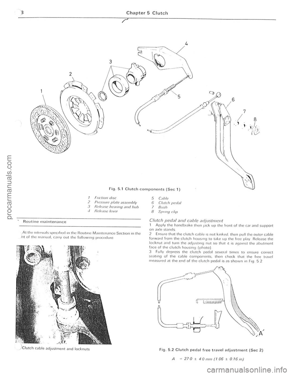
Fig 5.1 Clutch components (Sec 1)
Ruutine 1\1,lintC!1aIlCC
I FrwllO" d,sc ? }"".HIlfL' II/"'e ilHL'wlJly J "''''I.·o'R' /II .'''''''fJ oml 1001, ./ 11"',.""se /,."w"
AI tl1" U(itHv;lls spec(hud ((1 lh" llolll((1(J M ,((ntcnanCI! SeCI(OIlIll Ihe 111 of 11((1 Inilnu;!l. callY (Jut Ihe follow,,,\) pI<)c"dUlu
5 C"Ma 6 CI(I((:/' /1I:d,d 7 Rllsh 8 SI>tJlly dil'
CII/teh pUdo1l and c,1hle adjustment 1 Apply the handlH,lke til(:" J'lck lip the h01l1 ulthe Cill iII ld support 011 ilxle sl,lnds 2 Ensure thilt the c illtd, c;Jble 'S not klilked. Ihell pull the nllwr cilbt e 10lWilid hum the ch,tch houslI1g to lake up the f rec pl,lY Release the locknut ,1ud lurn the a(illlstln9 Ilut ~o thilt 11 IS an,lulst thc "i>utl1lenl f,Ke of the clutch houslnU (photo) 3 Fu lly dcp,e~s Ihe clutch pedill seve'ill ulnes 10 en~u'e correct seat ln\! of Ihe cable components. then check thilt the hOI! t(<
A .. 270t40mm(106± O/6J1l)
procarmanuals.com
Page 100 of 205

Chapter 5 Clutch 99
--.;,:;.~.--.
. '
3 I V,,'W 01 Ihe clutch wIth the Ue,IIbox r~movcd
1 If IH,<:~SS;lIy. ill'" Ihe
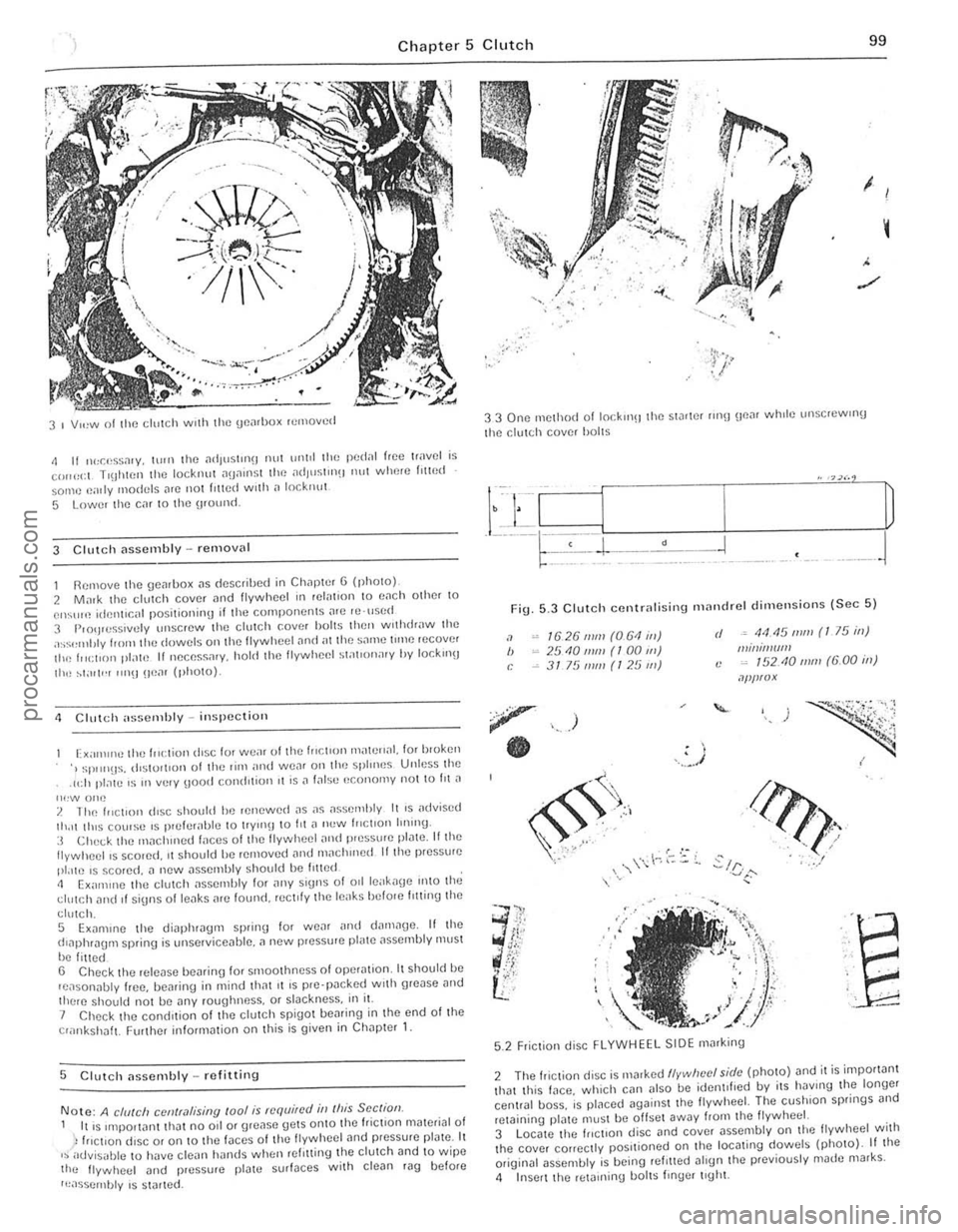
I Remove the ~Jenrbox .. 5 described in Chapter G (photo). 2 Ma,k Ihe chltd, cove,
II", ~1'''I'·r ""!I Uoar (photo).
1 Cili lch assemhly -inspectioll
Ex;"nIlIO IllI] 1", :lio n dISC lor we,ll ollhe In<:lIon 1ll'lIe"al. for bwkell .j ,;pllilUS. (ilSlull rOll of the rilll "ml we;lr all the splmos Unless the
. 1I:h plate IS In ve'y \Jood condlliull II is ;I false "cono"'y not 10 hi J
II""" ono ? The I"ctron d,sc should he ren ewed as as "ssemhly II IS adviscd Ih.ll th,s co\m;r~ IS prelelahle to lIymB 10 1'1 .. IIew I"ctlon IIIHIlU· :3 Chec k tho tnJchlned Iilces 01 Ihe flywheel "nd p'essure plate . lithe Ilywheells scoled. II should he relllove<1 "lid m~ch",cd Illhe preSSIJle pl.lIe IS scored.
cluic h nnd II si9nS 01 le"ks "re found. rec t,ly Ihe le"ks be/Ole hlling Ihe
clutch.
5 E x nmlllC Ihe diapl""9fll sprinu lor wear ,lIld <1
., Ch eck Ihe comt.tion ollhe dolCh spigol be .. ring in Ihe end 01 Ihe o""kshillt. Further inlorlllillion on this is given in Ch;lpICr 1.
5 Clu tc h assembly _ relitting
Note: A chI/eli CCII(r,l/ising roo/ is required in (his See (ion. I IllS IInpOllanllhal no od or gre.lse gelS onlO th(l friction mated,,1 01 h,c t,on diSC 01 on 10 the laces of Ihe lIywheel find pressure plalc. It ,~advisi,llle to have clean hands when rel'lIing the dolCh and 10 w ipe lho lIywheel ;lIld pressure [lla\\! surfaces wilh clean rag belore
I~assernhly IS s1
.... , ... "
'.
33 One method 01 10cklllH the Slarter lin!) \lo"r wlHle \II1SCleWll1U
the clulCh cover hailS
•
Fig . 5.3 Clulc h centr" lising nHllldrel dimellsio ns ISec 5 )
"
" ,
1626 111111 (061 ill) 25101ll11! (100 1ft) 3175 mill (125 1ft)
)
.. , . I .. ~ .
rI .• 44.15 mm (I 75 ill) IIImil!l(IfII (: ~ 15210111111 (6.00 ill)
.l/lf!f(!X
./J?f1. ' ,
.?!<'. , , ..... /
~/ r .... :./ .:..1('":'
'''r' ....... , .
. )i";; , i ,
. . ~:.. • j • ,
/'" , , -..
··E
"
.. . -
5.2 Friction disc FLYWHEEL SIDE marking
2 The friClion disc is Il,arkcd flvwlwcl shit· (photo) and il i$ impol1anl Ihal th is face . which can 11150 be idenl,lled by ils haVing the longe, cenllal boss. ;s plnced againSI Ihe lIywheel. The cushion springs and reJaining pl"te muSI b(l ollsel away hom lhe Ilywheei. 3 Loca te the Inctlon disc "nd cover "ssembly on t he lIywheel with the cover cOlleclly positioned on J he loc .. ting dowels (phOto) . If lhe oliginal assembly is being , efllled .. lIgn Ihe previously made marks .
<1 Insell Ihe reta,ning boilS I"'ger Ilghl.
,
I
I
I
I,
procarmanuals.com
Page 104 of 205

Chapter 6 Manual gearbo x and automatic tran smissio n
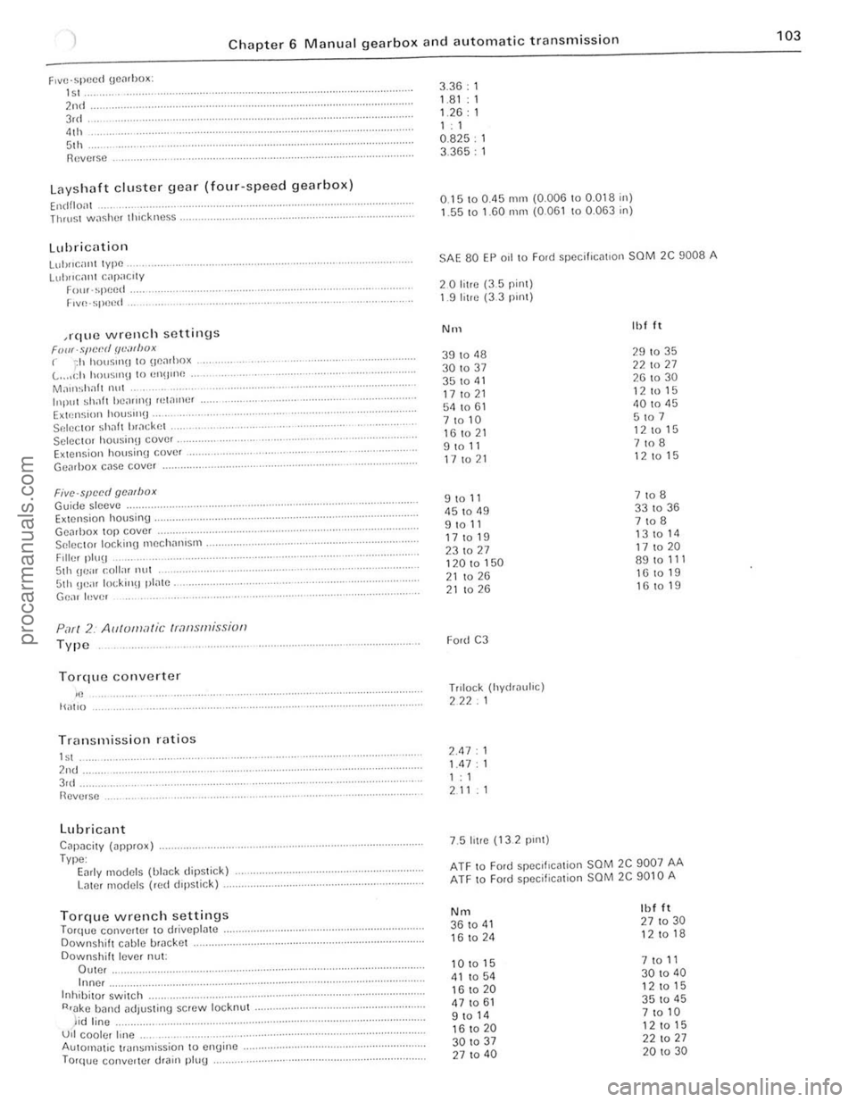
F1VO.Sp()od \joiuhox:
'" 2nd 3rd 41h .. 51h f\ovr;,so
Laysh aft cluster gear (f our-speed gearbox )
Elldfio
Luh"(.
InplIl shafT hoaun» 11,IJIIUlr ExtellSl!lIl hous',,» ... Sf:h,ClOr Shilh IJJil~kel . Sciccto! housinO cove, .... Extension housin\1 cover . GeJlhO x casc cover
Flve·spccdgc,lfbox Guide sloeve Ex lOnsion housing. Geol,hox top cover Seleclor locking mechanism .... FilII), plu(1 51h He,ll cull,H nul 5th
Type
Torque converter
if! IWtlO
Transmis s io n ra tios
1 st 2nd. 3'd . Reverse
Lubricant
C~pacily (ilpprOX) . Type :
Early models (blnck dipsl ic k ) Laler Illodels (red dipstic k) ..
T orque wrench settings Torque convcrter 10 dr;veplille .
Do wnshift cable brac ke l
Downshift lever nUl: Duler. Inner.
Inhibito r swilCh
R'ake b;"Uld ~d!usling screw loc knu l .. .
lid l ine .... ... .. ...... ........................... .... . ULI cooler Ime . AU10lllilllC t",n~lI1ission t o engine. To rque conveilei drJin plug
3.36 : 1 1.81.1 1.26: 1 1 ,
0.825. 3.365 :
0.15100.45 mill (0.006 to 0.018 in)
1 .55 to 1.60 m!11 (0.061100.063 in)
SAE 80 EP oil 10 Ford spociflCatlon SCM 2C 9008 A
20 lit,e (35 pim) 1.9 lilH! (3.3 PUlt)
NIl
39104 8 30 to 37 35 to 4 1 17 10 2 1 54 to 61 71010 161021 9 to 11 17 to 21
9 to 11 4 5 10 49 9 to 11
17 to 19
231027 12010150 21 to 26
2 1 1026
Ford C3
Tnlock (hydrnulic)
222.1
2.47 : 1.4 7 : 1: 1 2 11 : 1
7 .5
htre ( 1 3 2 pUl1)
Ih l It
29 10 35 22 to 27 261030 12 to 15 40 to 4 5 5107 12 10 15
7 to 8 1 2 10 15
7108 331036 7 to 8 13 10 1 4
17 1 0 20 89101 1 1 1610 19
16101 9
ATF to Ford spec,fIC~lion SaM 2C 9007 AA ATF to Ford specification SCM 2C 9010 A
N m Ill f It
361041 27 10 30
16 to 2 4 1
2 to 18
1
010 15 7
to 1 1 41 1054 3010 40
1 6 10 20 12 10 15
4 7
10 61 35 10 45
9 10 1 4 7 10 10
1610
20 12 10 1 5
3010 37 22 1
0 2 7
2 7
10 40 2
0 to 30
, . ,
!
.5 ________________ ........... ........
procarmanuals.com