1974 FORD CAPRI ABS
[x] Cancel search: ABSPage 158 of 205

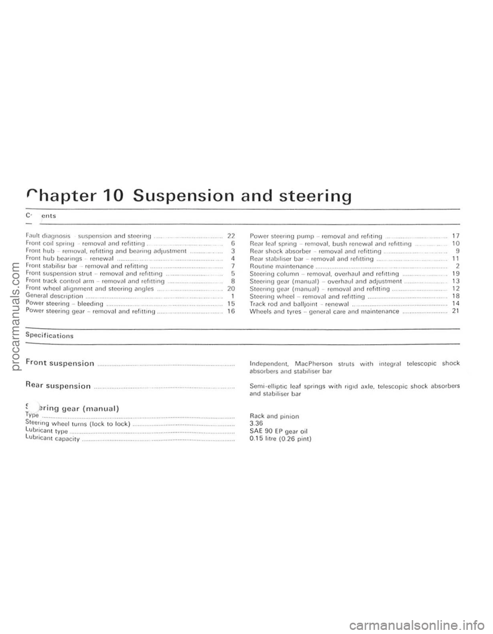
rhapter 10 Suspension and steering
F
Front suspension
Rear suspension
, . , enflg gear (manual) Type ................... ....................•................ Steeling whecl turns (lock to lock) .. . LUbrican t type ............. ................. ...... . lUbricant capacity _ ............................. .
" G 3 ,
7 ,
• 20 1 15
"
Powel stCCIlIlg Ilump .. remOllal ,111(1 fcllting RCiU leill SI)II119 . emoval. bush renewal .1nd Iclottlng Flo;"), shock iJbSOfOO' removal ,m(/ felUtlng , ............... , Rein sl
Steering column -rCmov
Steeling wheel -rCfllov
Wlleels nlld lyres -uencrill CilfC and maintenance ...................... .
17 10 9
" 2 19 13 12 ,.
" 21
Independent. MacPherson strutS with Integral telescopic shock
ab sorbers
Rack and
pinion 3.36 SAE 90 EP gea r oil 0.15 IlIre (026 pint)
i
i.
!
I (
!
:~
I:
II
procarmanuals.com
Page 159 of 205

)8 Chapter 10 Suspension and steering
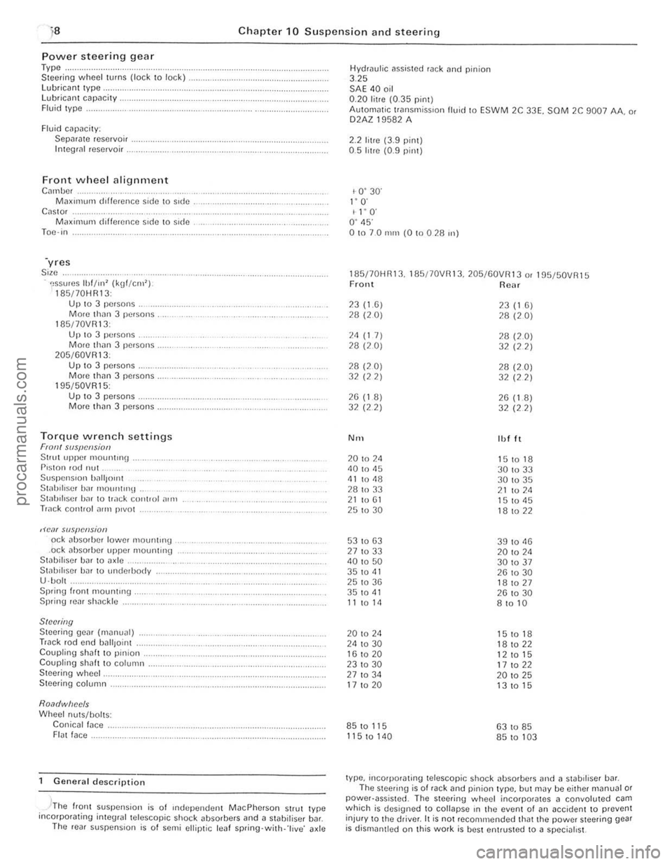
Power steerin g gear Type .. Steer ing wheel turns (lock to lock) lubrican t Iype, Lubricant capacity . Fluid Iype .
Fluid cilpacily: Sepilrilte reservoir . Integli!1 reservoir .
Front wheel alignment C",nbc, M;lXll11um dlffcrence side \0 side C
195/50VR15: Up 10 3 pe.sons . Morc th(ln 3 persons.
Torque wrench settings Fran! SIIS{!cl!siotJ Stlut upper 1110untrng . P,ston rod nut Suspen Sion ')~",{Jont St;rhiliscr birr mount"'lt . Stab iliser h;rr to track control ,)In,
Track cOIHlol ~rrn p,vot
,H'o1( slIspCIlsion od abso,bcr lower mountH'g .ock absorber upper mounting Stabillser bar to axle .. St;rl.lIlIscr har 10 underbody
U ·bol . Sprinu I.ont mount"'g . Spring rear sh;rckle
SINNing Steering gear (m~nual) Track rod end uall,oint Coupling shaft to pinion. Coupling shah t o column . Steering wheel.
Steering column.
Roa(/wiJec/s Wheel nuts/holts: Conicall;rce . FI(lt face.
General description
, -'The flonl suspension is of Independen t MacPherson Strut Iype incorpotating inleglal telescopic shock ~bsorbers and a stabilisel b~r. The ,eal suspens ion is o f semi ellip tic leaf spring·with· 'l ive ' axle Hydrau
l
ic assisted rack tlnd pinion 3.25 SAE 40 oil 0.20 litre (0.35 pint) AulOm
1- 0 ' 30' I" O· I l' O' O ' 45' 01070 nun (0 !O 0 28 ",)
185170HR13. 185/70VRI3. 205/60VR13 o. 195f50VR15 Front Rear
23(1.6) 23 (1 6) 28 (20) 28 (20)
2<1 (1 7) 28 (2.0) 28 (20) 32 (22)
28 (20) 28 (2.0) 32 (22) 32 (22)
26 (1 8) 26 (1.8) 32 (2 2)
32 (22)
N'H Ibl It
20 to 2<1 151018 40 to 45
30 to 33 <11 to <18 30 to 35
28 to 33 21 to 211 21 to 61 15 to <15 25 to 30 18 to 22
53 to 63 39 to 11 13 27 to 33 20 to 2<1 40 to 50 301037 35 to 41 26 to 30 25 to 36 181027 35 to <11 26 to 30 11 to 14 8 to 10
20 to 24 15 to 18 24 to 30 18 to 22 16 to 20
12 to 15 231030 17 to 22 27 to 34 20 to 25 17 to 20 13 to 15
85 to 115 63 to 85
115 to 140 85 to 103
type, incorporating telescopic shock absorbers and ;l stabdiser bill. The steering is of rack and pinion type, but may be either m(lnual or power·assisted . The steering wheel incorporates 11 convoluted cam which is designed to collapse rn the event 01 (In accident to prevent
injur y to Ihe driver. It is not reco mmended that the power steering gear is dismantled on Ihis work is best entrusted to a specialist.
procarmanuals.com
Page 162 of 205

Chapter 10 Suspension and steering 161
fig. 10.11 Drivebelt [ldjustlllent pulley holts on 3.0 litre models -arrowed (Sec 2)
2 Routine maintenance
At the "*',vals spec ,f,ed III the Routine MainhHlance $()(;t,on in the front of til() manunl c,lIIy out the 101l0wlIl\j p,o(;cdures.
Check lyres for illflalioll, wear and conditioll 1 Check [lnd If necessary adjust the tyre pressures .
2 Check [III t yres for WC[lr and condition with referenc e to Section 21
Check power steering pump drive belt tensiof) 3 Check thm the deflection of the drivebelt m,dway ulon!) its lonyest nlll between upper pulleys is approxirn
(photo).
Clwck puwer steering fluid levef (lnd hydraulic huses II pOSStble the level should be checked w,th the Buid [It nOll1lal
uper,\!mg tClIll)Cr[lture . 6 On c;lrly modcls unscrcw the wing nut nnd relnove Ihe rese,voir cover ilild uaskel. The flu,d should be up 10 Ihe MAX level mark on the
reservo". 7 On later models, wrn tht! hiler C
Fig. 10. 5 Topping·up the power steering reservoir on early models (Sec 2)
8 Whele nec.ess.1'y ~dd Ihe ~pccilled lIU1d to bring Ihe level up to the
correct ,nilrk. 9 ChC(;k the hydr[luhc hoses for comJit,on and security.
Check steerinfj ,-md suspension components 10 n,ll$O tilt) front ilno reM 01 the Cill or position over an inspeclion pn. 11 Check the SleetinlJ wck and t'e 'rods for d[lm3ge und weM. Also check the wek HJbber bellows and track rod end rubber bOOIS for spfilS
ilnd leilk[lge. 12 Chec k the front ,md reilr suspension components lor d"m.Jge [lnd wear. In particuf;lr check the front suspension tr.Jck control Mm ilrod stahiliwr r"bber mounling bushes. Usc a lever to check that there is no excessive we[lr III the Iron I slispenSlon lower IJ[ll lJoints which Me
"'\()\JIill wnh the track conlrol ilflllS . 13 Check the operat,on of the I,ont ;IIHt rear shock absorbers This is
be st ilchievcd with thO} Cilr on the \lfOlind by depressing euch corner of the ca' 1111\I1. On 'ele[lsil\ljthe C()"H~r helllU checked Ihe body should ,,~c thell s"llie IIlIl11ed,mely on ,t~ way down. II there nrc sever.J1 ()sclll;ot'ons the sho(;k absorber IS weilk nnd should be renewed.
3 Front hub _ removal. refitliny and bearing adjustillent
Apply the h[llldhr[lke then Jilek tip the front 01 the cm ilnd support
on axlt! standS Remove til(! rOildwhecl 2 Rernove the front ul;lke CJllper With ,elerence 10 Ch.Jpter 9. Whele the flex,ble br[lke host! is connecte(t dueclly to the cililper ther e IS no need 10 disconnect the hose i1S thO} caliper can be suspcnded by wire
aWily from the diSC. 3 By calelul 1
" :<>,:,~,.
Adjusting the power Sleering pump drivebelt tension on the 2.8 litre engine
2.7 Powcr steeling filler c.Jp/d,pstlck for the 2.8 hIre engine
3.3 Removing the dUSI cap from the front
hob
i
i ,
~ !
procarmanuals.com
Page 164 of 205

Chapter 10 S uspension and steering 163
~~--,,$iJO
~~\~
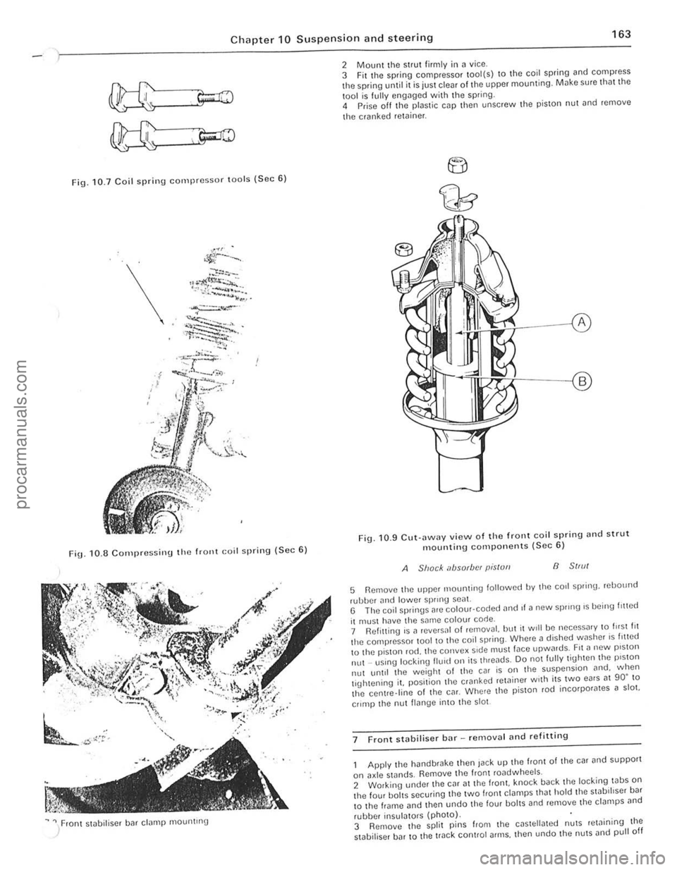
Fig. 10.7 Coil spri n g compressor lOo ls (Sec 6 )
\.
FiU. 1 0 .8 C o rn pressi nu the frOllt Goil spring ( S ec 6)
~ " / ron t stobiliser bar clamp mountrng
2 Mount the strut firmly i n ~ vice .
3 Fit t he spring compressor tool(s) to the coil spring and compress the spring until it is juSt clear of the upper mounting. Milke sure tho t the
1001 is f ully engilged with the spring.
4 Prise off Ihe plastic cap then unscrew Ihe pis ton nut ~nd remove
t he cranked
retoiner .
F ig . 10 .9 CU\·
ilWilY view o f th e front coil spring nnd strut mountin g compo nents (Sec 6)
A Shack absorbfN pis/ull B 51,,11
5 Remove Ihe upper 1110unling lollowed by Ihe corl spring. rebOllnd
rubber and lowe r sprrnU seal. G The coil springs are colour· coded ,1nd II a new sprong 's being I,!led
il muSI hilve the same colour code.
7 Ref itting is a reve,sal 01 removal. but il Will be neceSS
lhe centre.line of Ihe CM. Where the p iSlon rod incorpor
II~nge into the 5101
7 F ront stabiliser bar -removal
he hand brake then Jack up the front of the car and supporl
on axle stands. Remove Ihe fronl roadwheels.
2 Working under Ihe CM at the Irani. knock back the loc king tabS on the four baits securing tile two f,ont ct~mps Iha t hold the swb,hser ba r
t o the frame and then undo t he four bol tS and remove lhe clampS
,
I " I , ,
j
!
procarmanuals.com
Page 167 of 205

,6 Chapter 10 Suspension and steering
A
l
I Lr;=::;;r""~Jj'Q l
G-cc;;;;-~---~~~~~
, " I : I 'II
'I' , ,
, ,
FiU · 10.11 Fl(Wr stniJiliscr b;H flnd piece positioning (Sec 11)
A IJ 2620 I J!J 111111 (/03 101m) 100111111 (0·1 mJ
1"'5 ;",(1 ,0.:1'1 tile t;1\{1 sHoec When l ilted. the wHip'cec should he 1'''~'ll'''H,,1 .15 shown III FlO 1011 DIIIlCIlS'Oll A should he betweell ?!.i 59 nlld 2Gtl 5 ""ll (102 ami 104 JI') :lnd Ih" (h(fmcncc IWlwr!f!1l IllI! two s"I"5 IIll1S! nOI he \l'catc, th.1rl 2 5 nUll (0 1 m)
(l II Ihe IJl,~hcs "' II", (,11(1 11".:';'$ "''1''''<) """,wi,I, II 'llaV I", found "'O'e COI1V"Il
h",,/.ul1,11 h.'vel (the wUIOht ",qlllred IS dpp'ox,m
J.!Ck lip the front 0 1 thn C,lr and place s1
2 Remove tile nul ~lId holt from the elnmp at the front of tile fleXIble COllpll ll(1 on the steerm!j colllllln, Tills cl,IInp hOlds the couplln(J to the pillion splines.
3 Working on the front crossmemlier, knock hilek the lockmg wbs orl the two bolts on each IJck houslllg U ·C lillllp. undo the bolt ~nd remove tbe locking tabs ~nd clamps
4 Remove Ihe split pillS
Th iS cnn be done by ensuflng that the d,swnces hetween Ihp. ends oj bOlh trllek rods 1111(1 the Stec1inu geilr hOllslng on both sides ~re the same .
7 Place the stee"ng Uear in it s 10c
-,
Fig. 10,12 COfrect position o f stnhiliser bar ruhher bush {Sec11 )
T'!jht(:n the holts to Ihe speclf,(:{! to"lne, 9 Relit the I.,lck rod ends into the stO)(:IIn!) illluS. refIt (he I:a';[ellolted nllts and II!Jhten them to the slleclfl{)d tOlque Use new spill pillS to '!:t.nn the nuts
10 T'!lhten tho I:I,II"P bolt (HI the steeru'!J COItIllHI lIex'hle couphllU to 1f1n spec""~d torque. h,)vIlI!) fll~t rnil(\e SlJlOl tholt tlul pin lOll is cOlfecily 10(;"101(1 III t he S"III1CS 1 1 Lower the cm to tho urOllnd. thcn check nrld If neceSSo1ly ildJlIst the front whlwl ;III(J 'Hncnr 015 descrd)ed in Sec lion 20.
13 Stcerinu geM (Illanual) -overhaul <111(1 adjustment
Remove tlllltr ilc k rod nnds (Section 14) then .elllove 1)nd discard the Wile retalnlllg cliPS. remove the hellows and drall1 the I"hricant 2 Mount the stee"ng Ijear in
15 LubrientIJ the ball Seilts. balls and housings. with the specified gear 011 Screw the locknuts OntO the ends of the steeling (1)ck. 1 G Assemble t he sprlllgs. waShers. bJIl seJts. track rOd ends and housing. Tighten the hOllsmgs. to obwin a rowtionnltorque of 7 N m (5 Ibf It). then lock them w ith the locknuts. Recheck the torque alter tiuhtening the locknut 17 Drill new holes (even If the o ld holes Jre in aliunment). 4 mm {O, 16
______________________________ .1
procarmanuals.com
Page 178 of 205

) Chapter 11 Bodywork and fittin g 17 7
~!t~InS its oriOin,11 sh~flC. There is lillie point in trying to restore the original s hllpe complClC ly, as the me1011 on the darnllged arca will have stretched on impact ilnd cannOl be reshaped fully !O its original contou r, II is belter to bring the level of the dellt up to 11 poin t which is aboul ~ in (3 111111) below the level 01 the surrounding bodywork . In cases whe.e the dent is very shallow anywi'lY. i, is nOI worth trying \0 pull 1 ou t 111 all, II the ull{lersidc 01 the dent is accessible. il can be hammercd oul gently from behind, using a malleI with a wooden or plastic head. WhilSt doing Ihis. hold a suitable block of wood l'flllly a{),111151 the outside 01 the panel 10 absorb the impact from the hammer blowS and thuS Il,event 11 Imge area of the bodywo.k hom being 'belled,ouf, Should tho dem be in a section of tho bodywo.k which has iI double skin or SOI1IIl other filclOr mokil1g It inaccesslhle from behind, a
dllferent technique is cillied lor, Drill severill sm;1U holes through the
mewl II1slde the i1reil (Jilrtlcul,ldy in tho deeper section, Then screw long sel1·tap~ing screws into the holes IllSt suffIcien tly for Ihem to gilln iI good purchase In the mewl. Now the Ilen t C"n he 1)lJlled out by pulllllg on the protruding headS of the screws wllh iI pnll of pliers. The no.t stilgo of the rep,lir is the .emOllill of the PilUlt from the 113Ued meil, and hom nn Inch or so of tho SurroundlilU 'SOUfl(r
Jdywork , Tills is accomplished most oilslly by usil1U a wire brush or ab'~sllle pild on " ,)owe< dflll, ~,lthou9h It Clln he done Just i1S e ively hy hnmf usmg shoots 01 1I1)'i151110 P.l,)C •. To COlll,llete the p
thorelore decide whether to renew the whole polllel (II this IS possihle) or to .ep[lir the affoctod illoa. New body Po1nols arc not ,1S expensive as mos t flCOple think and it is often (Iuicker and mo.e satislacto • .,. to fit" new t)anelthan to auempt to rellair larue n.e,1S 01 corrosion.
RenlOlifl all f,llln\Js hom the .. lIeeted a.o" cxcoptthose which Will
act ~s ,1 uu,(ie t o the oliUllwl shape 01 the (i,lIlla\je(i bodywork (ell hn,1(1lnll1l) ~h.~lIs etc). ThOll, USlnu tin snIps or ~ h"cks
d epreSSion fo r Ih c frllcr pas\(!
'll/lle hrush the aHected Me[l to 'CIilOlle tiro powdery rust from the ,ICO 01 the lelllilllllll!l lIlet,,1 P;lInl thc "flected arc" wllh lUst
IIII"I)ltll1l) p""'t. If the hilck 01 the ,usle.1 me,1 's accesSlhle treolt tillS
" delo.o frlhflU cml t
me sh. or altlflll1l1um t",Joe. AlulIll"'um 0' pl;1strc mesh IS Il.oh"bl.,. lile hest m
Aluminium wpe should be us ed lor slll ;rll 0' vCly narrow holes. Pull a picce oil tho .011 ond tri'" It to tho apIl
ove . the hole, rt C[ln be overlapped II tho thickness of one piece is
i nsufficient. Burnish down the 00ges of tho tapO With the handle 01 "
screwdrillC ' or srmllOf, to ensure that the ",po.s securely auached to the
metal undomeath .
Bodywork rCIJ<1irs -filling a"d re-sprayi"g BefOte uSlIlg thiS Seetion, soe the Sections on denl. doep scratc h.
rust holes "nd gash repai.s . M~ny types of hodyfllfer Me ~val'ahlo, but Uonerally spe~k.ng those nrOpnelOry kits which conlain 0 till of f illor paste and a tube of resin h~fdener Me best for this type of rcp,llf A wide, !ieKilJle pl
hardener carefully (follow the m"kCI's instructions on the pack) othe.wrse thO folic. Will !>tt too rill)luly or tOO Slowly . Using the
"pplicator apply the filler paste to Ihe prcpared area: draw the
applicalOr across the surfaco 01 tho IllIer to achieve the correct contour and to lovel the fillef surface. As soon /1S it contour that approxim"tes 10 thO corrOCt one is achielled, SlOp wo.kinU the pas le - il you carryon too long the pasto will becomc sticky and begin to 'pick up' on tho
app lic"tol. Continue to add thin layels of Iiller paste at twenty· minute intervals until the level of the filler is just pfoud of the surrounding bodywork Once the IllIer has hardened, excess can be removed using a met;!1 plane or IiIe. F.om then on. progressively finer grades of abrasive paper should be used. starling with a 40 grade p.oduction paper and l.nishing With 400 o."de wet·and·dry paper . Always wrap the abrasille p"pcr IIrOUlld a flat rubber, cork. or wooden block -otherwise the surfaco 01 the frller Will nOI be completely flat. DUling the smoothing of the fIller SUI face the wel·and·dry paper shoufd be periodically rinsod in walCr. ThiS will ensure thaI alle.y smooth linish is imparted 10 the frller (It th O flllni SHIIJO. At t!\l S st1lge the 'dont ' shoul(! be surrounded by a ring of bme
mowl, whIch in IUfn Should he encirclod !.Iy the finely 'feathered' edge
0 1 th e good paintwork . Rinse tho repair nrea wilh clean water, until all 01 the dust I>roduced by the rubblllu·down operation has gone. Sp."y the whole .ep.1ir a.oa with" light coat of primer -this will show UI> any ,mpcrfOChons in lhe su.face of the fll1e •. Repai. theso Iml)CdectlOIlS with frosh 1,110' paste or bodySlOpper, and onco mOte
smoOth the sUfl
he call1od out in a w".m, dry, wind loss and dus t free atmosphero. This condition can be created mtllicially II you have access to a large indoor working "reil. but rl you nre lorced to work in the open. you Will have to pick your day lIe.y ca.efully . II you a.e working indoors. dousin\J the
floor in the work mea with water will holp 10 SOllie the dust which would otherwise be in the iltmosphe.e . If the ,epai. mea is con fined to one bod.,. pilllOl, mask off tho SUffoundlflg panels; lhis Will hell) 10 minllllise tho effocts 01 a slight mis,match in lH,lint colou.s Bodywo.k hUUlUS (eU ch.omo strips. door handles Otc) Will "'SO noed to be
"';1sked ot! Use uenume fII
S ilray on t he t op CO"1. "\Jain bUlldmu ull the tluckness by usul9
sOllof1lllhlfl'"ye .s 01 p<111l!. S Ia .t spraying in theCllnlre 01 the .epair mOil and theil, USH\g a clfcular mOllon, work outwards untrlthe whole ropmr
"rea ond al>out 2 inches 01 tho surrounding origmal pallltwork IS COvered Remolle allm"sklng mnteflaf 1010 15 minutes alter spr
Plastic compOllc"ts Wllh the use 01 mo.o and more pl"stic l>ody components by the
vehrcle manufac turers (eg bumpers, spolle.s. and in some cases major
body panels). reCllilcation 01 damago to such items .hilS .t.>e<:0me a
mOller o f eHhor emruSling relhl'r wOtk to a specialist m thiS field, o. renewing complete components Rep"ir by the DIY owner is nOlleillly feaSible owing to Ihe cost of the equipmen t and materials reQui.ed for effecting such repairs. The baSIC technique inllolves making a grOOllo
atong th o hno of the crack in the plastic using a rotary hurr in a pow~r drill. The damnged pal! is then welded hack togeth er by uSing a hot "" gun to heat up nnd luse a pl
polyca.bonate. ABS, poIYllropylene) .
procarmanuals.com
Page 204 of 205

fault diagnosis -172 leaf spling .emoval. bush renewal and refitting -165 maintllnance. louline -161 shock absorber remoyal and refitting -165 stabiliser bar removal and refitting -165 lorque wrenCh settings -158 R"ays -225 Rep.ir procedures, general - 9
Rocker e rms (3.0 litre engine) examinat ion and renovation -51 removal - 49 Rocker arms and coverl (3.0 litre engine) ref itting -55 Rocker assembly (2.8 litre engine) dismantling. examina tion and reassembly -34 Routine maintenance stt Maintenance. routine
5
Safety precautions - 12 Seat belts -191 Seats .emoval and refining -192 Sidelight bulb renewal -213 Spare parta buying -8
to carry in ca. - 19 Spark p lugs conditions (colour) -91 lemoval. servicing and .elilling -95 Speedometer cable renewal - 226 Stabiliur bar Iront -163 rear -165 Starter moto r
description -207
d ismant ling and reassembly -207
removal and refi tting -207 testing on engine -207 Steering column removal. overhaul and refitt ino -170 desc.iption -158 faull diagnosis -172 f,on t wheel alignmenl ~nd steering angles -171 gear (manual)
ove,haul and adjustment -166 removal and refittin g -166 maintenance. rouline -161 power steering bleeding -168 gear removal and refitting -168
pump femoval and refining - 168
specifications _ 157 torque wlench senings -158 track rod end balljoint renewal-167
whea' removal and refitt ing -168 Sump 2.8 litra engine
refining -44
removal and refining with engine in car -34 3.0 litre engine refitting -55 removal -50 Sunroof bracket and dr ive assembly lemoval and refitting -191 panel adjustments -189 removal and refining _ 190 Suspension lfnd steering _ 15 7 tl seq Suspension see Front suspension Imd Re ar suspension jtches removal and relining
Index
T
central facia - 225
door p illar - 224 handbrake warning light _ 225 hazard warning -223
ignition -224
instr um
ent cluster illum ination _ 224 light and windscreen wiper (Series II) -225 load sp':)ce lamp -225 steerin g column multi-Iunction -224
s top lamp - 152
Tailgate priv ate lock removal and relining -187 .emoval and refilling -187 striker plate removal and relin ing - 188 wnsher
nozzle removal and refitting -217
pump rllmov31 and refitting -217 window glass removal and relitting -180 wiper mOlOr and linkage remoyal and refitting -217 Tappets (3.0 litre engine) remoyal -50 Tappets and push rods el
care and maintenance -171 presswes -158 size -15 8
Underframe
maintenance -16. 176 Upholstery maintenance -176
v
Vacuum servo unit (braking system) description -156 lemov~! and refining -156 Valves clearances checking and adjustment -46 . 55 Valves (3.0 titre engine) removat -49 Valves and va lv e seats (3.0 litre engine) examination and renovation -52 Vehicle identification numbers - 8
255
procarmanuals.com