Page 25 of 86

Downloaded from www.Manualslib.com manuals search engine FLOOR CONTROLS
Braking System
The service brake system is de
signed for braking performance
under a wide range of driving con
ditions even when the vehicle
is
loaded to its full rated vehicle load.
Power Brakes
• On cars with power brakes if
power assist to the brakes
is
interrupted due to a stalled en
gine
or some malfunction, two
or more brake applications can
be made using reverse power.
• If the brake pedal is held down ,
the system
is designed to bring
the car to a full stop on reserve
power. However, the reserve
power
is partially depleted each
time the brake pedal
is applied
and released.
• When reserve power is ex- hausted,
the vehicle can still be
stopped by applying greater
force to the pedal.
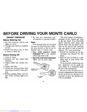
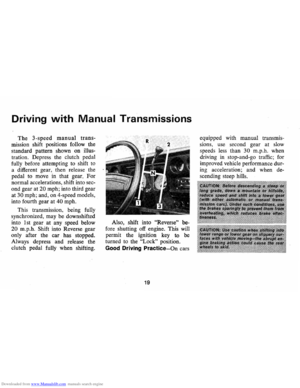
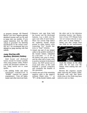
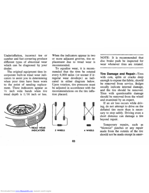
Parking Brake
• To set parking brake, fully de
press foot pedal at far left side.
• For maximum holding power,
depress regular brake pedal with
the other foot at the same time.
• To release parking brake, pull
"BRAKE RELEASE" lever on
lower left instrument panel.
• As a reminder, the brake system
warning light
is designed to glow
whenever the parking brake con
trol
is not fully released, and the
ignition
is on.
• Never drive car with parking
brake set
as this may overheat
or otherwise damage rear brakes.
23
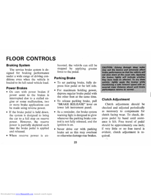
Clutch Adjustment
Clut8h adjustment should be
checked and adjusted periodically
as necessary to compensate for
clutch facing wear.
To check, de
press pedal by hand until resist
ance
is felt. Free travel of pedal
should be approximately one inch;
if very little
or no free travel is
evident, clutch adjustment is re
quired.
Page 26 of 86

Downloaded from www.Manualslib.com manuals search engine NOTE: "Riding the brake" by rest
ing your foot on the brake pedal
when not intending to brake can
cause abnormally high brake tem
peratures, excessive lining wear
and possible damage to the brakes.
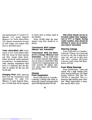
REMINDER: Brake linings should
be inspected for wear by a quali
fied mechanic at least once a year
or every 12 ,000 miles, whichever
occurs first. (Disc brake pads
should
be visually inspected for
wear each time the wheels and
tires are rotated at
6,000 mile in
tervals.) More frequent inspec
tions should be made if driving
conditions in your area, such as a
traffic or terrain, or techniques of
individual drivers result in frequent
brake applications. Your Chevro
let dealer
is best qualified to advise
you as to how often this inspection
should be performed. When brakes require
relining, use those Genuine
General Motors
Parts specified
for your car, and Delco Brake fluid
as required .
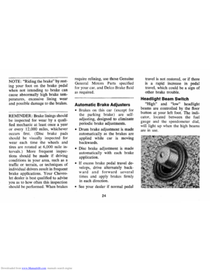
Automatic Brake Adjusters
• Brakes on this car (except for
the parking brake) are self
adjusting, designed to eliminate
periodic brake adjustments.
• Drum brake adjustment is made
automatically
as the brakes are
applied while
car is moving
backwards.
• Disc brake adjustment is made
automatically with each brake
application.
• If excess brake pedal travel de
velops, drive alternately back
ward and forward several
times and apply brakes firmly
in each direction.
• See your dealer if normal pedal
24
travel is not restored, or if there
is a rapid increase in pedal
travel, which could be a sign of
other brake trouble.
Headlight Beam Switch
"High" and "low" headlight
beams are controlled by the floor
button at your left foot. The indi
cator, located between the fuel
gauge and the speedometer dial
will light
up when the high beam~
are in use.
Page 27 of 86
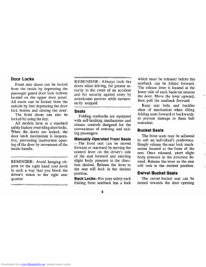
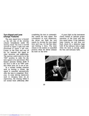
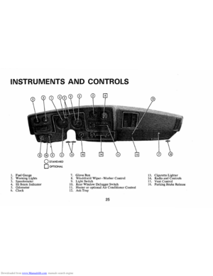
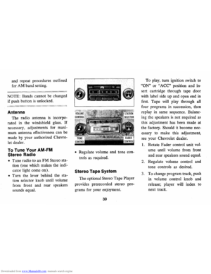
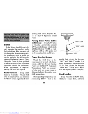
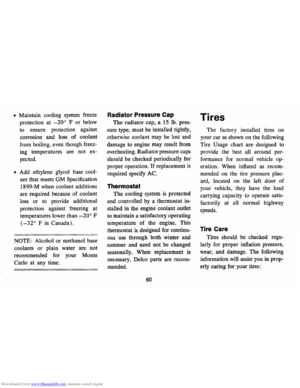
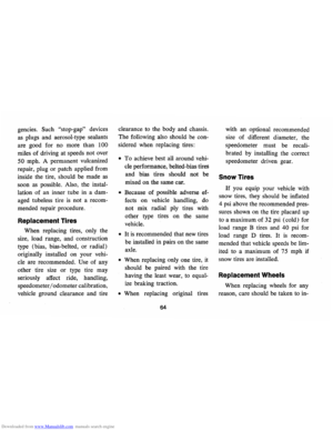
Downloaded from www.Manualslib.com manuals search engine INSTRUMENTS AND CONTROLS
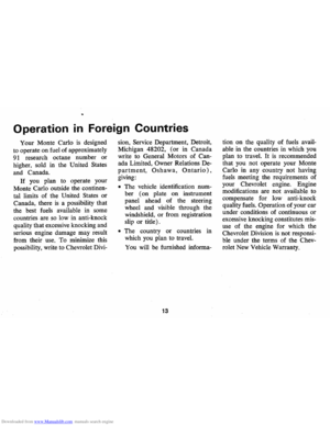
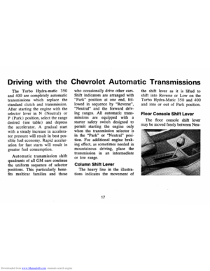
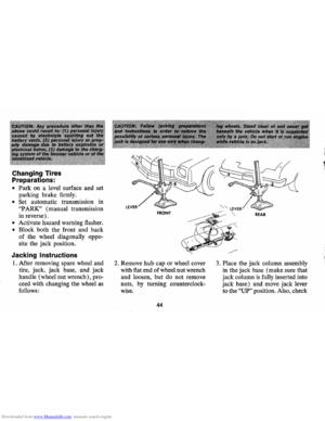
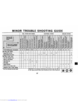
o STANDARD
o OPTIONAL
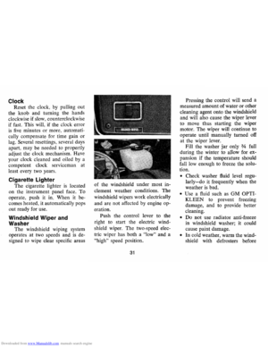
1. Fuel Gauge 7. GloveBox 13. Cigarette Lighter
2. Warn ing Lights 8. Windshield Wiper-Washer Control
14. Radio and Controls 3. Speedometer 9. Light Switch 15. Vent Control 4. Hi Beam Indicator 10. Rear Window Defogger Switch 16. Parking Brake Release 5. Odometer 11. Heater or optional Air Conditioner Control 6. Clock 12. Ash Tray
25
Page 28 of 86

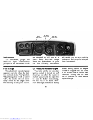
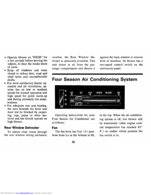
Downloaded from www.Manualslib.com manuals search engine Instruments
The instruments, gauges and
indicator lights conveniently
grouped in the instrument cluster
Fuel Gauge
This electrically operated gauge
registers correctly when the igni
tion switch
is in the "on" position.
When the ignition switch
is turned
"off", the needle will not neces
sarily return to the empty mark
but may stop at any point on dial. are
designed to tell you at a
glance many important things
about the performance of your
car. The foIlowing information
Oil Pressure Indicator Light
This light will be on when the
ignition switch
is turned on and
s hould
go out after the engine is
started. OccasionaIly the light may
be seen to flicker momentarily,
but this will do no harm. How
ever , if the light remains on during
26
will enable you to more quickly
understand and properly interpret
these instruments .
normal driving speeds the engine
should be stopped until the cause
of the trouble ca n be located and
corrected. Driving the
car with
low oil pressure can cause serious
engine damage.
Page 29 of 86

Downloaded from www.Manualslib.com manuals search engine Generator Indicator Light
This light provides a quick
check on the generating system
of your car. The red light will
go on when the ignition key
is
in the "on" position, but before
the engine
is started. After the
engine starts, the light should go
out and remain out.
If the light
remains on when engine
is run
ning , have your Authorized Chev
rolet Dealer locate and correct
the trouble
as soon as possible.
Engine Temperature
Indicator Light
This indicator light is provided
in the
instrument cluster to
quickly warn of an overheated
engine. With the ignition switch
in the
START position, the red
TEMP indicator will light to let
you know that it
is operating
properly. When the engine
is started, the red
light will go out immediately.
It will light up at no other time
unless for some reason the engine
reaches a dangerously high oper
ating temperature.
If the red light
should come on, the engine must
be stopped until the cause of the
overheating
is corrected. Glance
at instrument cluster frequently
as
you drive to see if this light is on.
Brake System Warning Light
The service brake system is
designed so that half of the brake
system will provide some braking
action in the event of a hydraulic
leak in the other half of the
sys
tem. If the warning light located
below the fuel gauge glows con
tinuously when the ignition
is on
and after the brakes have been
firmly applied, it may indicate that
there
is a malfunction in one half
of the brake hydraulic system.
27
• As a check on bulb condition
the light should glow with the
parking brake applied and the
ignition on. (Light
is also a
reminder to release parking
brake) .
• Have system repaired if light
does not come on during check.
• This warning light is not a sub
stitute for the visual check of
brake fluid level required
as
part of normal maintenance.
If the light glows red:
• The parking brake control is not
fully released or,
• The service brake system is
partially inoperative
What to do:
1. Check that the parking brake
is released. If it is ...
2. Pull off the road and stop,
carefully- remembering that:
Page 30 of 86

Downloaded from www.Manualslib.com manuals search engine • Stopping distances may be
greater.
• Greater pedal effort may be
required .
• Pedal travel may be greater.
3.
Tryout braking operation by
starting and stopping on road
shoulder -then:
• If you judge such operation
to be safe , proceed cautious
ly
at a s afe speed to nearest
dealer for repair.
• Or have car towed to dealer
for repair.
Continued operation of the car
in this condition
is dangerous.
Headlight Beam Indicator
Light
The headlights of your car have
high and low beams to provide
ybu
with proper night-time visibility
for most driving conditons . The
"low" beams are used during most
city driving. The "high" beams are especially
useful when driving
on
dark roads since they provide ex
cellent long range illumination.
The headlight beam indicator will
be on whenever the high beams
or
"brights" are in use. The Headlight
Beam Switch controls the headlight
beams (see
Page 24).
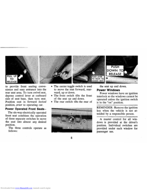
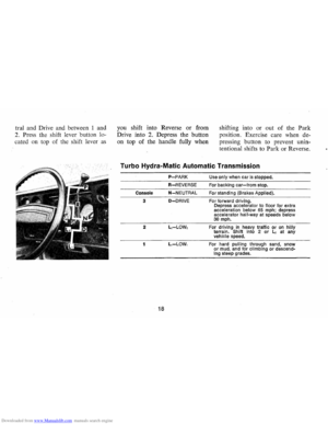
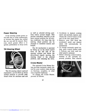
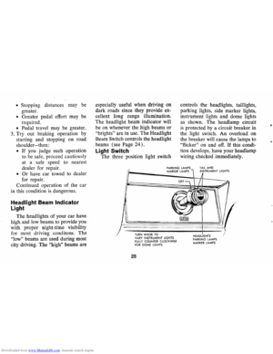
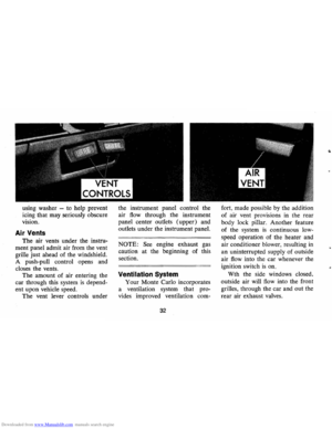
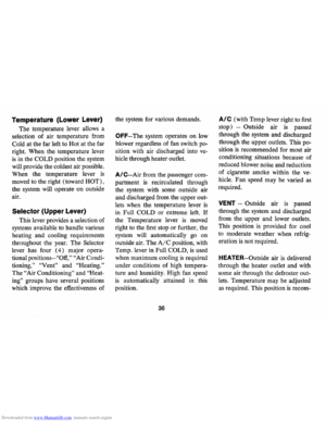
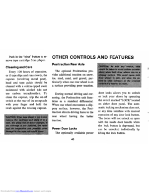
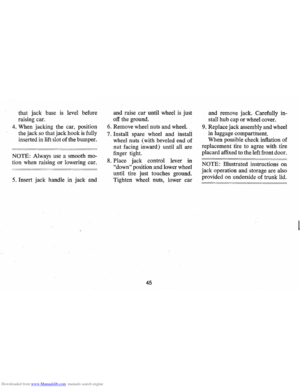
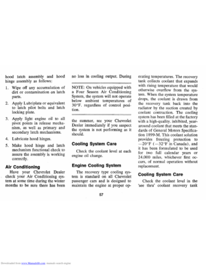
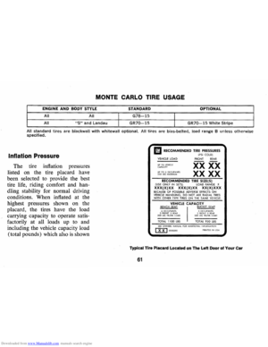
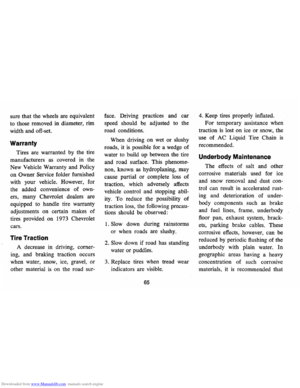
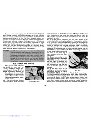
Light Switch
The three position light switch controls
the headlights, taillights,
parking lights, side marker lights,
instrument lights and dome lights
as shown. The headlamp circuit
is protected by a circuit breaker in
the light switch. An overload on
the breaker will cause the lamps to
"flicker" on and off. If this condi
tion develops, have your headlamp
wiring checked immediately.
PARKING LAMPS MARKER LAMPS TAIL AND INSTRUMENT LIGHTS
--,---.---~------ -- --------
TURN KNOB TO VARY INSTRUMENT LIGHTS fULLY COUNTER CLOCKWISE fOR DOME LIGHTS
28
HEADLIGHTS PARKING LAMPS MARKER LAMPS
•
Page 31 of 86

Downloaded from www.Manualslib.com manuals search engine _ '\' ' 2
1
5 , / '/ ,
[ e /~
O'v RPM !lOa -"-50
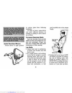
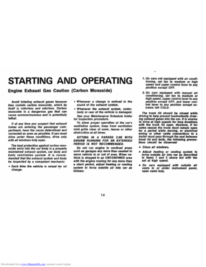
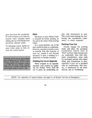
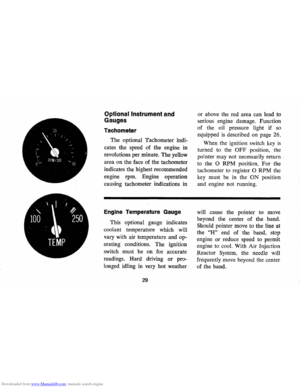
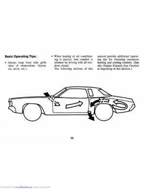
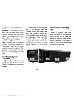
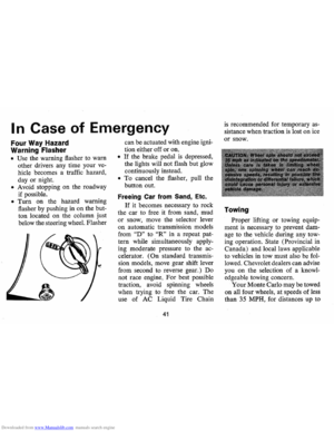
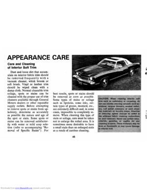
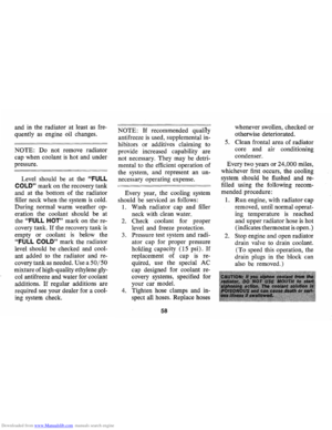
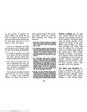
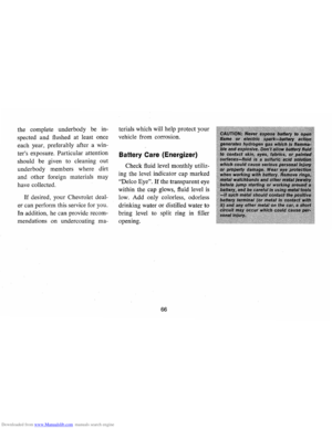
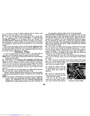
Optional Instrument and
Gauges
Tachometer
The optional Tachometer indi
cates the speed of the engine in
revolutions per minute. The yellow
area on the face of the tachometer
indicates the highest recommended
engine rpm. Engine operation
causing tachometer indications in
Engine Temperature Gauge
This optional gauge indicates
coolant temperature which will
vary with air temperature and op
erating conditions. The ignition
switch must be on for accurate
readings. Hard driving
or pro
longed idling in very hot weather
29
or above the red area can lead to
serious engine damage. Function
of the oil pressure light if
so
equipped is described on page 26.
When the ignition switch key
is
turned to the OFF position, the
pointer may not necessarily return
'
to the 0 RPM position. For the
tachometer
to register 0 RPM the
key must be in the
ON position
and engine not running.
will cause the pointer to move
beyond the center of the band.
Should pointer move to the line at
the
"H" end of the band, stop
engine
or reduce speed to permit
engine to cool. With Air Injection
Reactor System, the needle will
frequently move beyond the center
of the band.
Page 32 of 86

Downloaded from www.Manualslib.com manuals search engine I I
' /
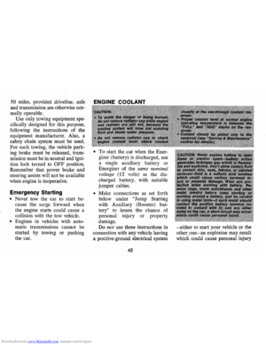
D C
4 t '
AMPS
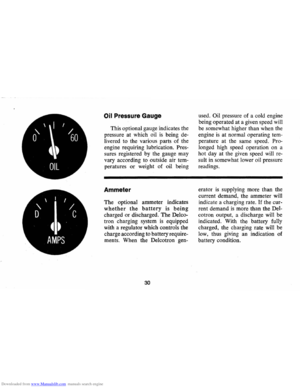
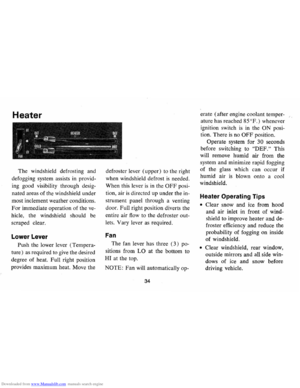
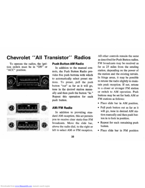
Oil Pressure Gauge
This optional gauge indicates the
pressure at which oil
is being de
livered to the various parts of the
engine
requiting lubriCation. Pres
sures registered by the gauge may
vary according to outside air tem
peratures
or weight of oil being
Ammeter
The optional ammeter indicates
whether the battery is being
charged or discharged. The Delco
tron charging system
is equipped
with a regulator which controls the
charge according to battery require
ments . When the Delcotron gen-
30
used. Oil pressure of a cold engine
being operated at a given speed will
be somewhat higher than when the
engine
is at normal operating tem
perature at the same speed. Pro
longed high speed operation on a
hot day at the given speed will re
sult in somewhat lower oil pressure
readings.
era tor
is supplying more than the
current demand, the ammeter
will
indicate a charging rate. If the cur
rent demand
is more than the Del
cotron output, a discharge will be
indicated. With the battery fully
charged, the charging rate will be
low, thus giving an indication of
battery condition.