1973 CHEVROLET CAMARO air conditioning
[x] Cancel search: air conditioningPage 25 of 84
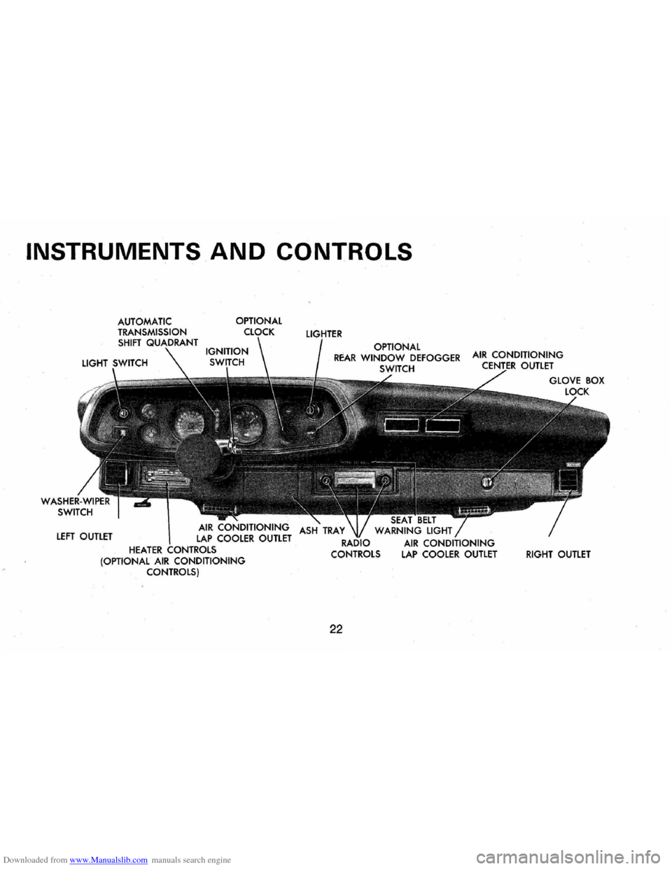
Downloaded from www.Manualslib.com manuals search engine INSTRUMENTS AND CONTROLS
OPTIONAL
LEFT OUTLET
HEATER (OPTIONAL AIR CONDITIONING CONTROLS) OPTIONAL
REAR WINDOW DEFOGGER SWITCH
22
WARNING LIGHT
AIR CONDITIONING LAP COOLER OUTLET RIGHT OUTLET
Page 31 of 84
Downloaded from www.Manualslib.com manuals search engine into the car whenever the ignition
switch
is on.
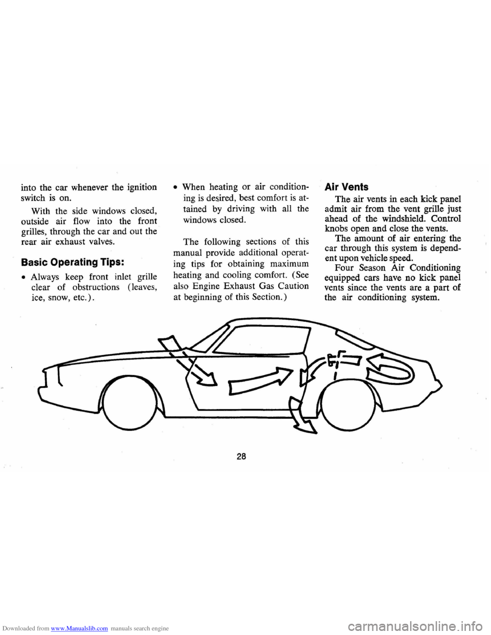
With the side windows closed,
outside air flow into the front
grilles, through the car and out the
rear air exhaust valves.
Basic Operating Tips:
• Always keep front inlet grille
clear of obstructions (leaves,
ice, snow, etc.).
• When heating or air condition
ing
is desired, best comfort is at
tained by driving with all the
windows closed.
The following sections of this
manual provide additional operat
ing tips for obtaining maximum
heating and cooling comfort.
(See
also Engine Exhaust Gas Caution
at beginning of this Section.)
28
Air Vents
The air vents in each kick panel
admit air from the vent grille just
ahead of the windshield. Control
knobs open and close the vents.
The amount of air entering the
car through this system
is depend
ent upon vehicle speed.
Four Season Air Conditioning
equipped cars have no kick panel
vents since the vents are a part of
the air conditioning system.
Page 33 of 84
Downloaded from www.Manualslib.com manuals search engine • Keep all windows and vents
closed to reduce dust, road and
wind noise and uncomfortable
drafts.
• For most satisfactory heater op
eration and air circulation , oper
ate fan
on low or medium speeds
for normal operation and high
speed for quick warm-up and
during extremely low tempera
tures.
• For adequate rear seat heating,
the area beneath the front seat
must not be blocked by carpet
ing, rags, paper or other mate
rial and fan should operate on
high blower.
• For additional summer ventila
tion move the
AIR lever to mid
position and the
DEFROSTER
lever to DEF. If greater air
flow is desired, move the FAN
lever down to operate the three
speed blower .
Rear Window Defroster
To insure clear vision through
the rear window during inclement
weather, the Rear Window De
froster has become established as a
popular accessory . This unit draws in
air from the passenger compart
ment and directs it against the back
window to remove frost or mois
ture . Its blower has a two-speed
control switch on the instrument
panel.
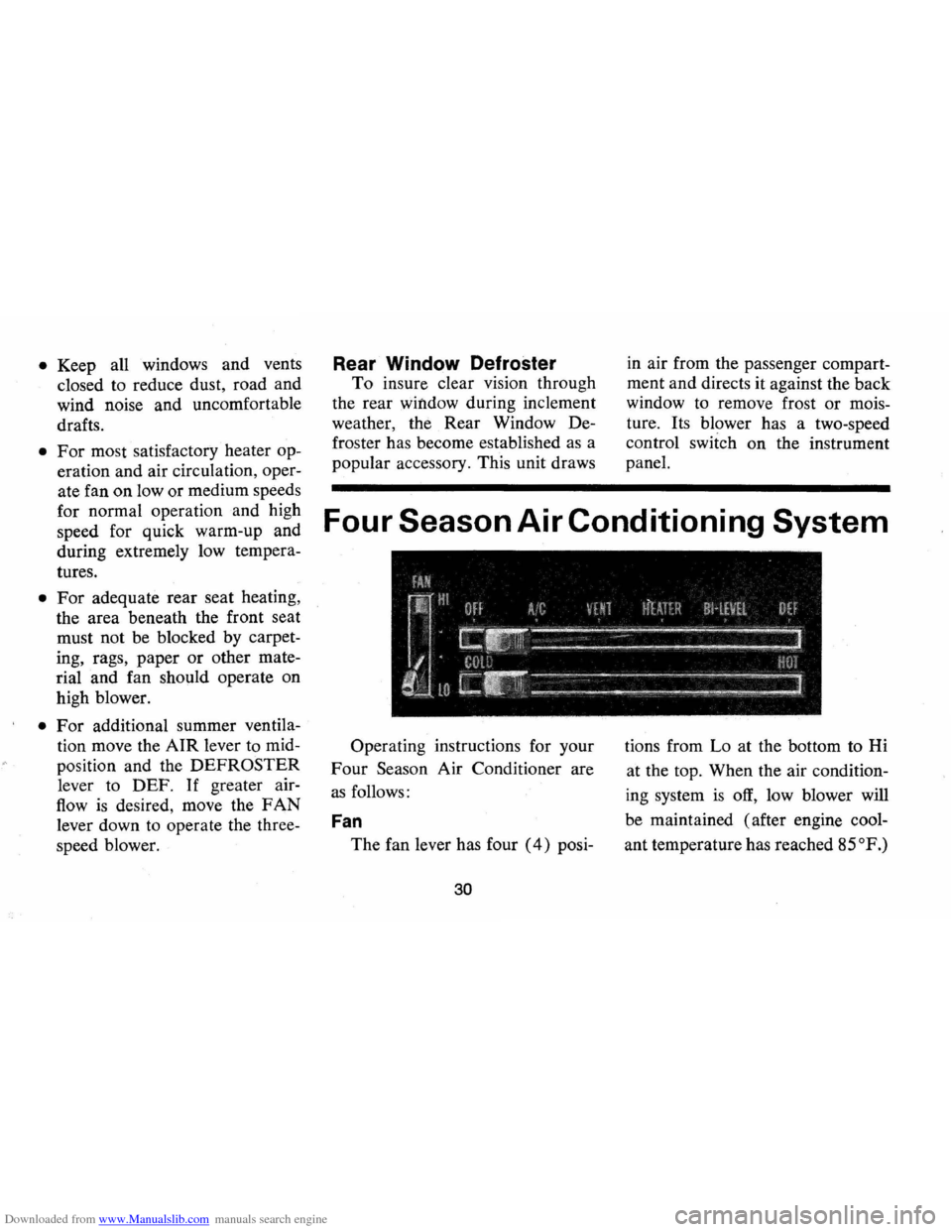
Four Season Air Conditioning System
Operating instructions for your
Four Season Air Conditioner are
as follows:
Fan
The fan lever has four (4) posi-
30
tions from Lo at the bottom to Hi
at the top. When the air condition
ing system
is off, low blower will
be maintained (after engine cool
ant temperature has reached
85°P.)
Page 34 of 84
Downloaded from www.Manualslib.com manuals search engine no matter which position the fan
switch
is in.
Temperature (Lower Level)
The temperature lever allows a
selection of air temperature from
Cold at the far left to Hot at the
far right. When the temperature
lever
is in the COLD position the
system will provide the coldest air
possible. When the temperature
lever
is moved to the right (toward
HOT), the system will operate on
outside air.
Selector (Upper Lever)
This lever provides a selection of
systems available to handle various
heating and cooling requirements
throughout the year. The Selector
lever has four
(4) major opera- tiona!
positions-"Off,"
"Air Con
ditioning," "Vent" and "Heating."
The "Air Conditioning" and "Heat
ing"
groups have several positions
which improve the effectiveness of
the system for various demands.
OFF-The system. operates on low
blower regardless of fan switch
position with air discharged into
vehicle through heater outlet.
A/C-Air from the passenger com
partment is recirculated through
the system with some outside air
and discharged from the upper
outlets when the temperature lever
is in Full COLD or extreme left. If
the Temperature lever is moved
right to the first stop or further,
the system will automatically go
on outside air. The
AIC position,
with Temp. lever in Full
COLD,
31
is used when maximum cooling is
required under conditions of high
temperature and humidity. High
fan speed
is automatically attained
in this position.
A/C(with Temp lever right to first
stop
)-Outside air is passed through
the system and discharged through
the upper outlets. This position
is
recommended for most air condi
tioning situations because of
re
duced blower noise and reduction
of cigarette smoke within the
vehicle.
Fan speed may be varied
as required.
VENT -Outside air is passed
through the system and discharged
from the upper and lower outlets.
This position
is provided for cool
to moderate weather when refrig
eration
is not required.
Page 55 of 84
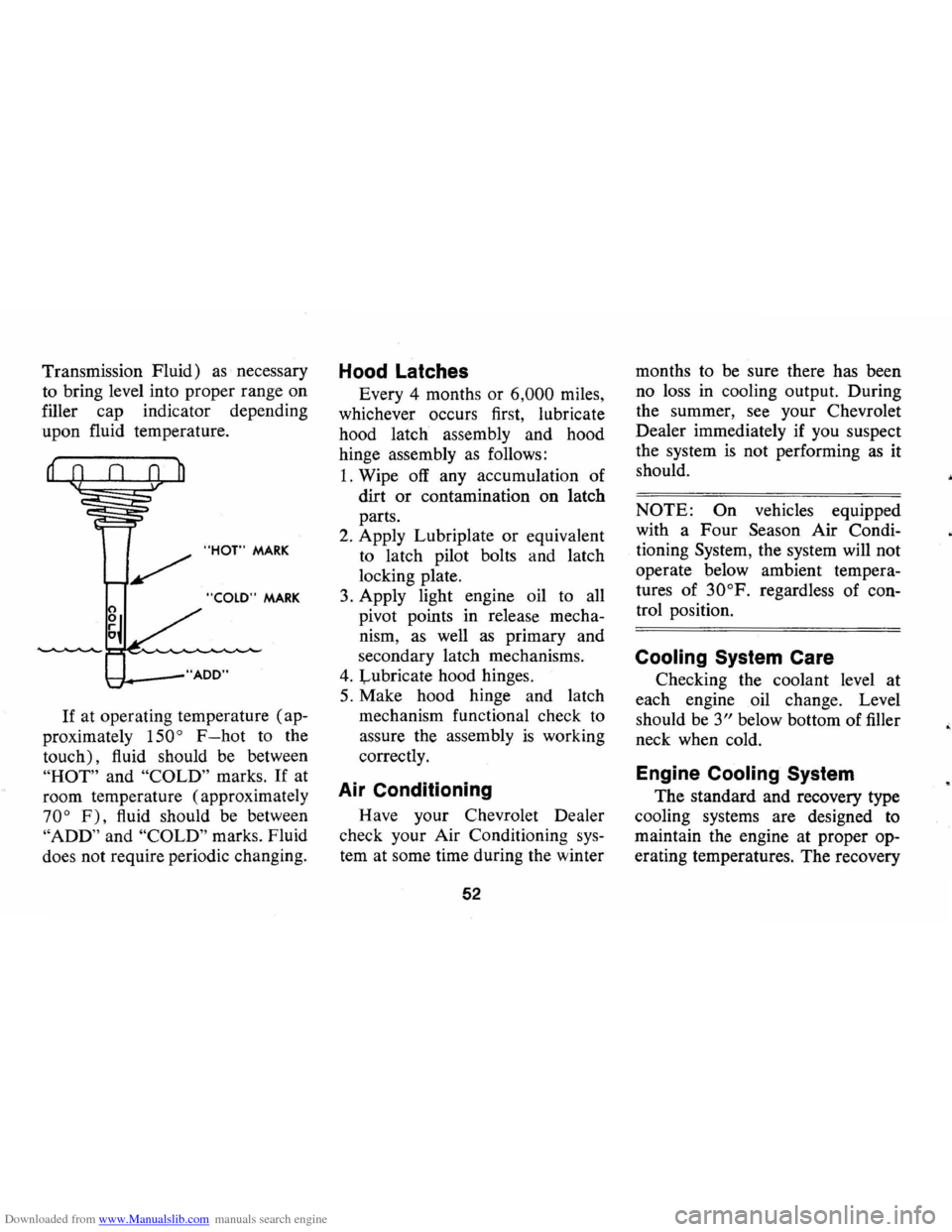
Downloaded from www.Manualslib.com manuals search engine Transmission Fluid) as necessary
to bring level into proper range on
filler cap indicator depending
upon fluid temperature .
"HOT" MARK
"COLD" MARK
t-"f. __ -"AOO"
If at operating temperature (ap
proximately
150 ° F-hot to the
touch), fluid should be between
"HOT" and "COLD" marks. If at
room temperature (approximately
70° F), fluid should be between
"ADD" and "COLD" marks . Fluid
does not require periodic changing.
Hood Latches
Every 4 months or 6,000 miles,
whichever occurs first, lubricate
hood latch assembly and hood
hinge assembly
as follows:
1. Wipe off any accumulation of
dirt
or contamination on latch
parts.
2. Apply Lubriplate or equivalent
to latch pilot bolts and latch
locking plate.
3. Apply light engine oil to all
pivot points in release mecha
nism,
as well as primary and
secondary latch mechanisms.
4. Lubricate hood hinges.
5. Make hood hinge and latch
mechanism functional check to
assure the assembly
is working
correctly.
Air Conditioning
Have your Chevrolet Dealer
check your Air Conditioning
sys
tem at some time during the winter
52
months to be sure there has been
no loss
in cooling output. During
the summer,
see your Chevrolet
Dealer immediately if you suspect
the system
is not performing as it
should.
NOTE: On vehicles equipped
with a Four
Season Air Condi
tioning
System, the system will not
operate below ambient tempera
tures of
30°F. regardless of con
trol position.
Cooling System Care
Checking the coolant level at
each engine oil change. Level
should be
3" below bottom of filler
neck when cold.
Engine Cooling System
The standard and recovery type
cooling systems are designed
to
maintain the engine at proper op
erating temperatures. The recovery
•
Page 56 of 84
Downloaded from www.Manualslib.com manuals search engine type cooling system is used on all
1973 Camaro air conditioned and
heavy duty cooling systems. It has
been filled at the factory with a
high-quality, inhibited, year-around
coolant that meets the standards
of General Motors Specification
1899-M. This coolant solution pro
vides freezing protection to
-20 0 F
(-32°F in Canada), and it has
been formulated to be used for
two full calendar years
or 24,000
miles, whichever first occurs, of
normal operation without draining,
provided the proper concentration
of coolant
is maintained.
• For Recovery Systems Only
Check the coolant level visually
at the see-through coolant reser
voir at each oil change interval
while the engine
is at normal
operating temperature. Do not
remove radiator cap except for
draining and refilling the system.
Coolant level should be at the
"Full Hot" mark on the reservoir.
If system is checked cold, the
coolant level should be at the
"Full Cold" mark on the reser
voir.
• For Other Than Recovery Sys
tems-Check the coolant level
only at oil change intervals, un
less there
is evidence of leaking
or overheating. Do not remove
radiator cap when solution
is
hot and under pressure. Coolant
level should be a maximum of
three inches below the level of
the filler neck when the engine
is cold.
• All Systems-Add a 50/50 mix
ture of high-quality ethylene
glycol antifreeze and water if
coolant additions are necessary.
Do not overfill.
NOTE: If recommended quality
antifreeze
is used, supplemental
inhibitors or additives claiming to
53
provide increased cooling capabil
ity are not necessary. They may be
detrimental to the efficient opera
tion of the system, and represent
an unnecessary operating expense.
Every year, the cooling system
should be serviced
as follows:
1. Wash radiator cap and filler
neck with clean water.
2. Check coolant for proper level
and freeze protection.
3. Pressure test system and radia
tor cap for proper pressure hold
ing capacity (15 psi).
If re
placement
of cap is required,
use the proper AC cap specified
for your car model.
4. Tighten hose clamps and inspect
all hoses. Replace hoses when
ever checked, swollen
or other
wise deteriorated.
5. Clean frontal area of radiator
core and air conditioning con
denser.
Page 70 of 84
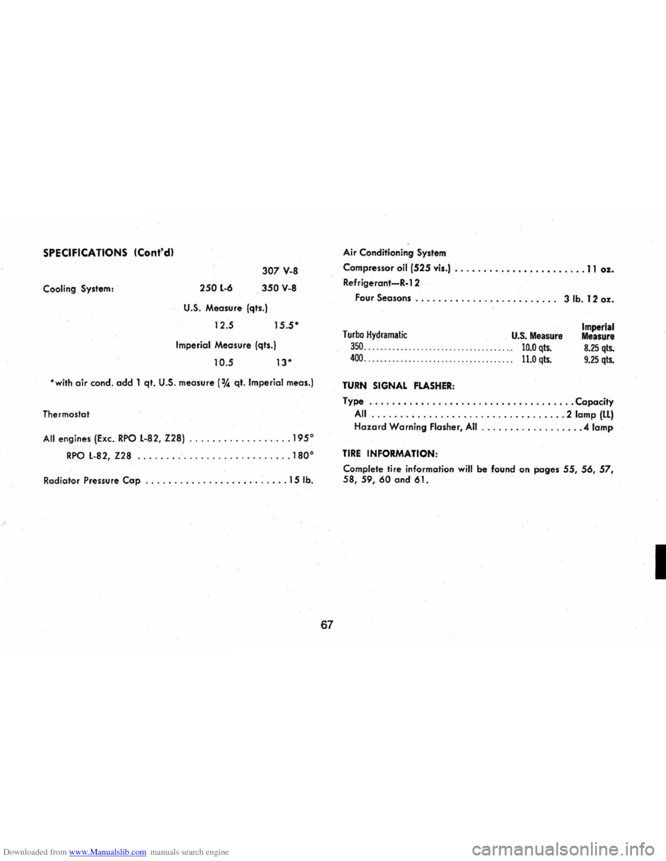
Downloaded from www.Manualslib.com manuals search engine SPECIFICATIONS (Cont'dl
Cooling System: 250 L-6
307 V-8
350 V-8
U.S. Measure (qts.)
12.5
15.5·
Imperial Measure (qts.)
10.5 13·
·with air condo add 1 qt. U.S. measure (3,4 qt. Imperial meas.)
Thermostat
All engines (Exc. RPO L-82, Z28) .............. .... 1950
RPO L-82, Z28 ........................... 1800
Radiator Pressure Cap ......................... 15 lb.
67
Air Conditioning System
Compressor
oil (525 vis.) .................... , .. 11 oz.
Refrigerant-R-l 2
Four
Seasons . . . . . . . . . . . . . . . . . . . . . . . .. 3 lb. 12 oz.
Turbo Hydramatic U.S. Measure
350. . . . . . . . . . . . . . . . . . . . . . . . . . . . . . . . . . . ... 10.0 qts.
400. . . . . . . . . . . . . . . . . . . . . . . . . . . . . . . . . . . . . 11.0 qts.
TURN SIGNAL FLASHER:
Imperial Measure
8.25 qts.
9.25 qts.
Type .................................... Capacity
All .................................. 2 lamp (LL)
Hazard Warning Flasher, All ................. .4 lamp
TIRE INFORMATION:
Complete tire information will be found on pages 55, 56, 57, 58,59,60 and 61.
I
Page 72 of 84
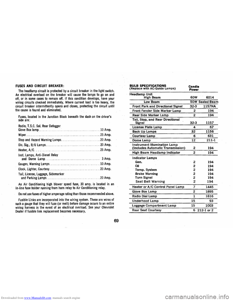
Downloaded from www.Manualslib.com manuals search engine FUSES AND CIRCUIT BREAKER:
The headlamp circuit is protected by a circuit breaker in the light switch. An electrical overload on the breaker will cause the lamps to go on and off, or in some cases to remain off. If this condition develops, have your wiring circuits checked immediately. Where current load is too heavy, the circuit breaker intermittently opens and closes, protecting the circuit until the cause is found and eliminated.
Fuses, located in the Junction Block beneath the dash on the driver's side are:
Radio, T.S.C. Sol. Rear Defogger Glove Box lamp .......................... .
Wiper .................. . .
..
10 Amp.
25 Amp.
Stop and Hazard Warning lamps .................. ... ..... 20 Amp.
Dir. Sig., B/U lamps .................... ............ .... 20 Amp.
Heater, A/C. . . . .. .. . .. .. . .. . .. .. .. .. . . .. .. .. .. . .. ... 25 Amp.
Insl. lamps, Anti·Diesel Relay and Dome lamp. 3 Amp.
Gauges, Warning lamps.. .. .
. .. .. . .. .... . . .. . .. .. . . .. .. .10 Amp.
Clock, lighter, Courtesy.. .. .. . . . . .. . .. ... .. .. . .20 Amp.
Tail, license, luggage, Sidemarker and Parking lamps ...... . .20 Amp.
An Air Conditioning high blower speed fuse,30 amp. is located in an In·line fuse holder running from horn relay to Air Conditioning relay.
Do not use fuses of higher amperage rating than those recommended above.
Fusible links are incorporated into the wiring system. These are wires of such a gauge that they will fuse (or melt) before damage occurs to an entire wiring harness in the event of an electrical overload. See your Chevrolet Dealer if fusible link replacement becomes necessary.
69
BULB SPECIFICATIONS (Replace with AC·Guide Lamps)
Headlamp Unit High.Beam
Low Beam
Front Park and
Directional Signal
Front Fender Side Marker Lamp
Rear Side
Marker Lamp
Tail, Stop, and Rear
Directional
Signal
License Plate Lamp
Back Up Lamps
Courtesy Lamp
Dome
Lamp
Instrument Illumination Lamp (Includes Automatic Transmission)
High Beam
Headlamp Indicator
Indicator Lamps
Gen.
Oil Temp. System
Brake Warning
Turn
Signal Seat Belt Warning
Heater or AIC Control Panel Lamp
Glove Box Lamp
Radio Dial Lamp
Underhood
Lamp
Luggage Compartment Lamp
Rear Seat Courtesy
Candle Power
60W 6014
SOW Sealed Beam
32·3 1157NA
2 194
2 194
32·3 1157
4 67
32 1156
6 631
12
211·1
2 194
2 194
2 194 2 194 2 194 2 194 2 194 2 194
7 1445
2 1895
1 1816
15 93
15 1003
6 212·1 or 2