Page 25 of 84
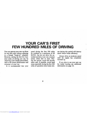
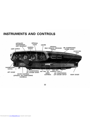
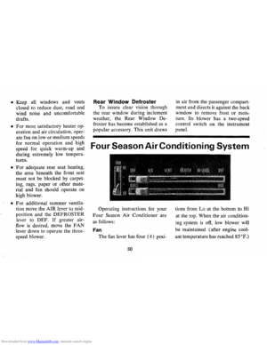
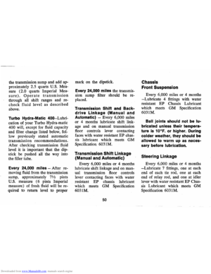
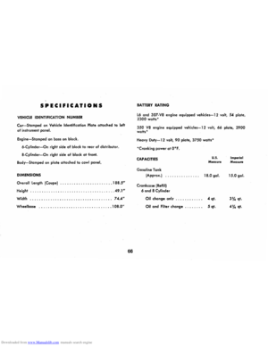
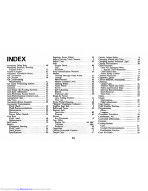
Downloaded from www.Manualslib.com manuals search engine INSTRUMENTS AND CONTROLS
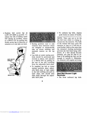
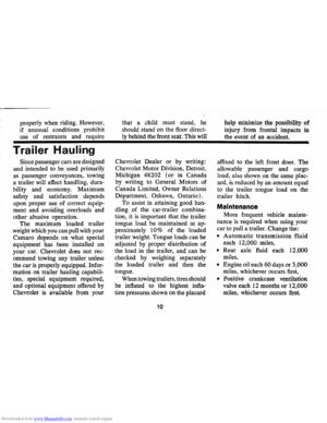
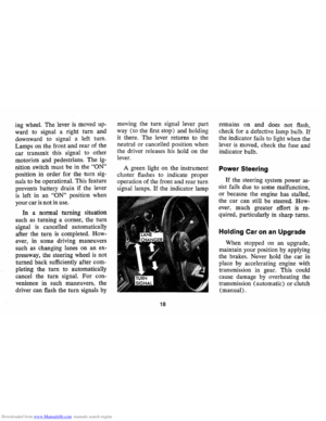
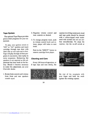
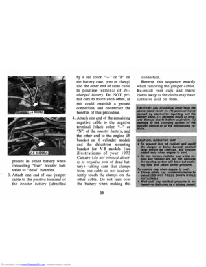
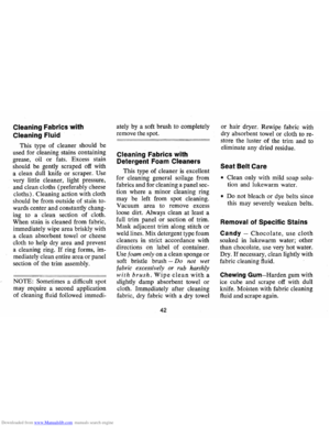
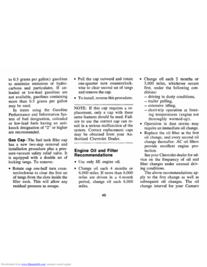
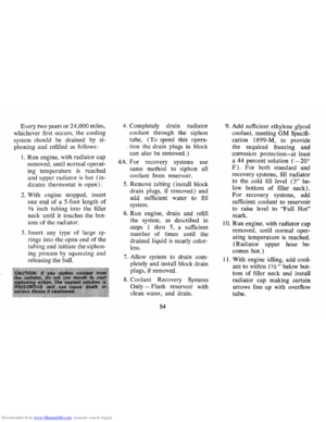
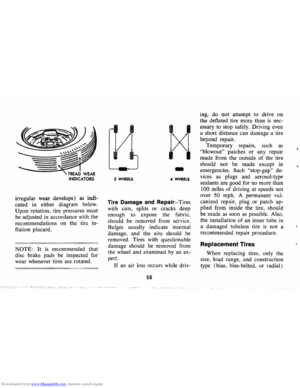
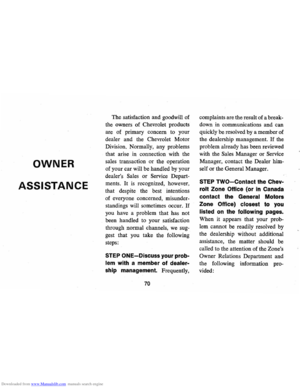
OPTIONAL
LEFT OUTLET
HEATER (OPTIONAL AIR CONDITIONING CONTROLS) OPTIONAL
REAR WINDOW DEFOGGER SWITCH
22
WARNING LIGHT
AIR CONDITIONING LAP COOLER OUTLET RIGHT OUTLET
Page 26 of 84

Downloaded from www.Manualslib.com manuals search engine Instruments
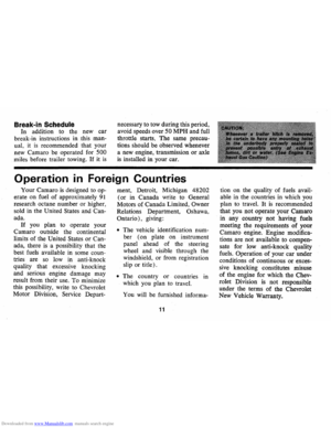
The instruments, gauges and in
dicator lights conveniently grouped
in the instrument cluster are de
signed to tell you at a glance many
important things about the per
formance of your car. The follow
ing information will enable you to
more quickly understand and prop
erly interpret these instruments .
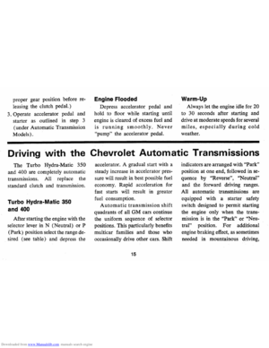
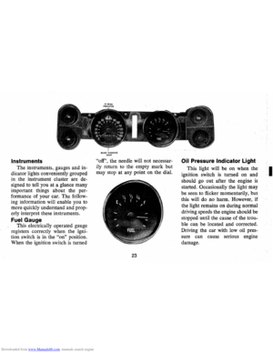
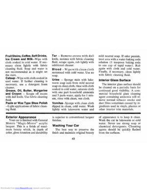
Fuel Gauge
This electrically operated gauge
registers correctly when the igni
tion switch
is in the "on" position.
When the ignition switch
is turned
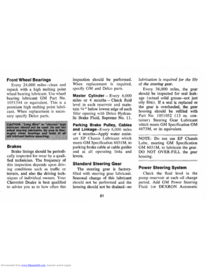
SRAKE WARNING UGHT
"off", the needle will not necessar
ily return to the empty mark but
may stop at any point on the dial.
23
Oil Pressure Indicator Light
This light will be on when the
ignition switch
is turned on and
should
go out after the engine is
started. Occasionally the light may
be seen to flicker momentarily, but
this will do no harm. However, if
the light remains on during normal
driving speeds the engine should be
stopped until the cause of the trou
ble can be located and corrected.
Driving the car with low oil pres
sure can cause serious engine
damage.
I
Page 27 of 84

Downloaded from www.Manualslib.com manuals search engine Generator Indicator Light
The red light will go on when
the ignition key
is in the "on" posi
tion, but before the engine
is
started. After the engine starts, the
light should go out and remain out.
If the light remains on when engine
is running, have your Authorized
Chevrolet Dealer locate and correct
the trouble as soon
as possible.
Engine Temperature
Indicator Light
This indicator light is provided
in the instrument cluster to quickly
warn of an overheated engine. With
,the ignition switch in the START
position, the red
TEMP indicator
will light to let you know that it
is
operating properly.
When the engine
is started, the
red light will go out immediately.
It will light up at no other time
unless for some reason the engine reaches
a dangerously high oper
ating temperature.
If the red light
should come on, the engine must be
stopped until the cause of the over
heating
is corrected. Glance at in
strument cluster frequently
as you
drive to see if this light
is on.
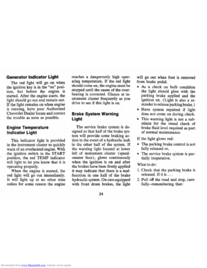
Brake System Warning
Light
The service brake system is de
signed
so that half of the brake sys
tem will provide some braking ac
tion in the event of a hydraulic leak
in the other half of the system.
If
the warning light located at lower
left of instrument cluster (speed
ometer face), glows continuously
when the ignition
is on and after
the brakes have been firmly applied
it may indicate that there
is a mal
function in one half of the brake
hydraulic system.
On cars equipped
with front drum brakes, the light
24
will go out when foot is removed
from brake pedal.
• As a check on bulb condition
the light should glow with the
parking brake applied and the
ignition on. (Light
is also a re
minder to release parking brake.)
• Have system repaired if light
does not come
on during check.
• This warning light is. not a' sub
stitute for the visual check of
brake fluid level required
as part
of normal maintenance.
If the light glows red:
• The parking brake control is not
fully released or,
• The service brake system is par
tially inoperative.
What to do:
1. Check that the parking brake is
released. If it is ...
2. Pull off the road and stop, care
fully-remembering that:
Page 28 of 84

Downloaded from www.Manualslib.com manuals search engine • Stopping distances may be
greater.
• Greater pedal effort may be re
quired .
• Pedal travel may be greater.
3.
Tryout brake operation by
starting and stopping on road
shoulder-then:
• If you judge such operation to
be safe, proceed cautiously at a
safe speed to nearest dealer for
repair.
• Or have car towed to dealer for
repair.
Continued operation of the car
in this condition
is dangerous.
Headlight Beam Indicator
Light
The headlights of your car have
high and low
beams to provide you with
proper night-time visibility
for most driving conditions. The
"low" beams are used during most
city driving. The
"high" beams are
especially useful when driving on
dark roads since
they' provide ex
cellent long range illumination.
The headlight beam indicator will
be on whenever the high beams
or
"brights" are in use. The Headlight
Beam Switch controls the headlight
beams (see Page
21).
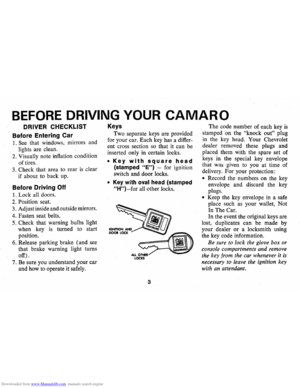
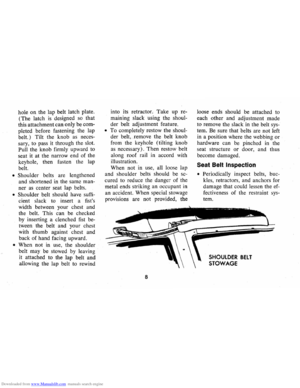
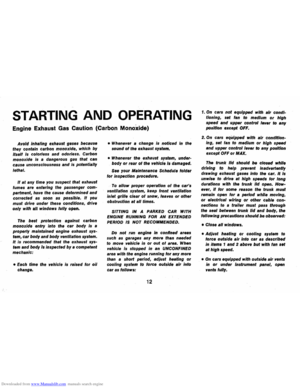
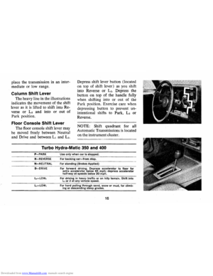
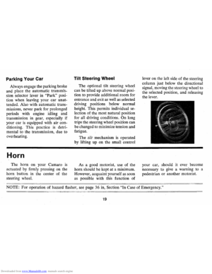
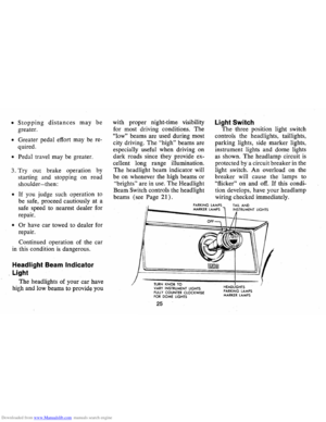
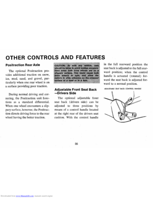
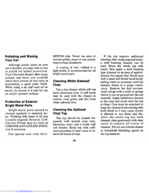
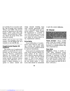
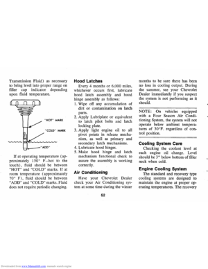
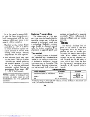
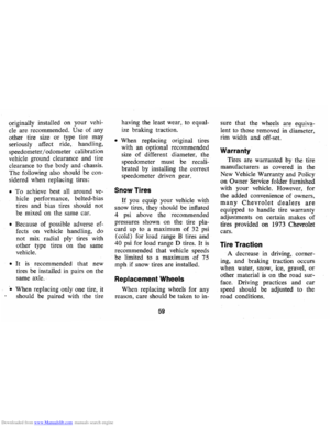
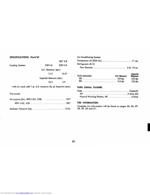
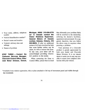
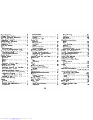
Light Switch
The three position light switch
controls the headlights, taillights,
parking lights, side marker lights,
instrument lights and dome lights
as shown. The headlamp circuit is
protected by a circuit breaker in the
light switch.
An overload on the
breaker will cause the lamps to
"flicker" on and off. If this condi
tion develops, have your headlamp
wiring checked immediately.
PARKING LAMPS MARKER LAMPS TAIL AND INSTRUMENT LIGHTS
TURN KN08 TO VARY INSTRUMENT LIGHTS FUll Y COUNTER CLOCKWISE FOR DOME LIGHTS
25
HEADLIGHTS
PARKING LAMPS MARKER LAMPS
Page 29 of 84

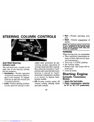
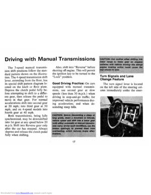
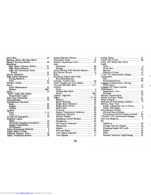
2530 35404550
15 55
10 60
5 65 RPM/tOO 70 Illm
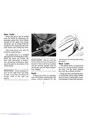
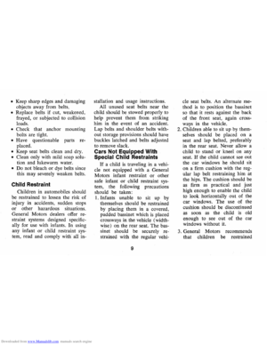
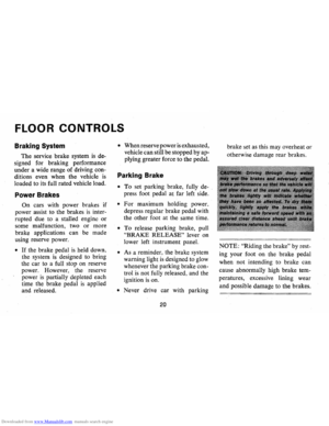
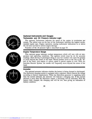
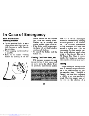
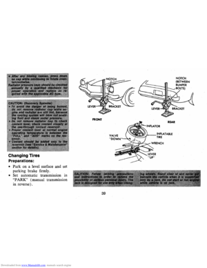
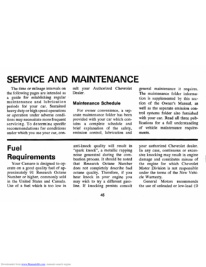
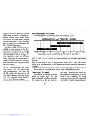
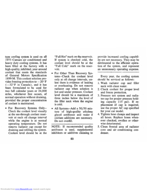
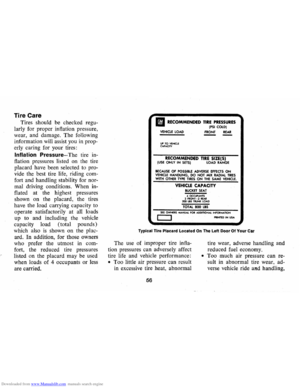
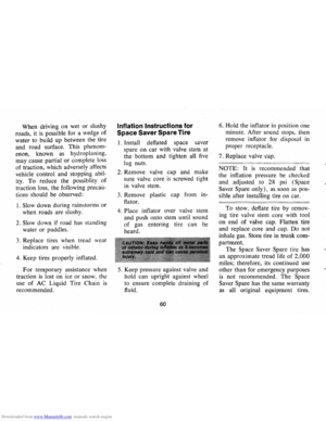
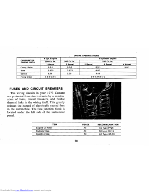
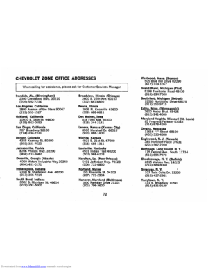
Optional Instruments and Gauges
Tachometer and Oil Pressure Indicator Light
The option")
Downloaded from www.Manualslib.com manuals search engine k)
2530 35404550
15 55
10 60
5 65 RPM/tOO 70 Illm
Optional Instruments and Gauges
Tachometer and Oil Pressure Indicator Light
The optional Tachometer indicates the speed of the engine in revolutions per
minute . The yellow are'a on the face of the tachometer indicates the highest recom
mended engine rpm. Engine operation causing tachometer indications in
or above
the red area can lead to serious engine damage.
Function of the oil pressure light
is described on page 23.
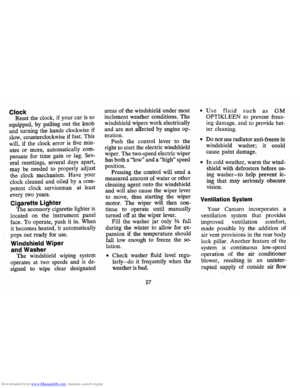
Engine Temperature Gauge
This optional gauge indicates coolant temperature which will vary with air tem
perature and operating conditions. The ignition switch must be on for accurate
readings. Hard driving or prolonged idling in very hot weather will cause the pointer
to move beyond the center of the band. Should pointer move to the line at the
"H"
end of the band, stop engine or reduce speed to permit engine to cool. With Air
Injection Reactor System, the needle will frequently move beyond the center of the
band.
Ammeter
The optional ammeter indicates whether the battery is being charged or discharged.
The Delcotron charging system
is equipped with a regulator which controls the charge
according to battery requirements. When the Delcotron generator
is supplying more
than the current demand, the ammeter will indicate a charging rate.
If the current
demand
is more than the Delcotron output, a discharge will be indicated. With the
battery fully charged, the charging rate will be low, thus giving an indication of
battery condition.
26
Page 30 of 84

Downloaded from www.Manualslib.com manuals search engine Clock Reset the clock, if your car is so
equipped, by pulling out the knob
and turning the hands clockwise if
slow, counterclockwise if fast. This
will, if the clock error
is five min
utes or more, automatically com
pensate for time gain
or lag. Sev
eral resettings, several days apart,
may be needed to properly adjust
the clock mechanism. Have your
clock cleaned and oiled by a com
petent clock serviceman at least
every two years.
Cigarette Lighter
The accessory cigarette lighter is
located on the instrument panel
face.
To operate, push it in. When
it becomes heated, it automatically
pops out ready for use.
Windshield Wiper
and Washer
The windshield wiping system
operates at two speeds and
is de
signed to wipe clear designated areas
of the windshield under most
inclement weather conditions. The
windshield wipers work electrically
and are not affected by engine op
eration. Push the control lever to the
right to start the electric windshield
wiper. The two-speed electric wiper
has both a
"low" and a "high" speed
position. Pressing the control will send a
measured amount of water or other
cleaning agent onto the windshield
and will also cause the wiper lever
to move, thus starting the wiper
motor. The wiper will then con
tinue to operate until manually
turned off at the wiper lever.
Fill the washer jar only
% full
during the winter to allow for ex
pansion if the temperature should
fall low enough to freeze the so
lution.
• Check washer fluid level regu
larly-do it frequently when the
weather is bad.
27
• Use fluid such as GM
OPTIKLEEN to prevent freez
ing damage, and to provide bet
ter cleaning.
• Do not use radiator anti-freeze in
windshield washer; it could
cause paint damage.
• In cold weather, warm the wind
shield with defrosters before us
ing
washer-to help prevent ic
fig that may seriously obscure
vision.
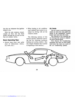
Ventilation System
Your Camaro incorporates a
ventilation system that provides
improved ventilation comfort,
made possible by the addition of
air vent provisions in the rear body
lock pillar. Another feature of the
system
is continuous low-speed
operation of the air conditioner
blower, resulting
in an uninter
rupted supply of outside air
flow
Page 31 of 84

Downloaded from www.Manualslib.com manuals search engine into the car whenever the ignition
switch
is on.
With the side windows closed,
outside air flow into the front
grilles, through the car and out the
rear air exhaust valves.
Basic Operating Tips:
• Always keep front inlet grille
clear of obstructions (leaves,
ice, snow, etc.).
• When heating or air condition
ing
is desired, best comfort is at
tained by driving with all the
windows closed.
The following sections of this
manual provide additional operat
ing tips for obtaining maximum
heating and cooling comfort.
(See
also Engine Exhaust Gas Caution
at beginning of this Section.)
28
Air Vents
The air vents in each kick panel
admit air from the vent grille just
ahead of the windshield. Control
knobs open and close the vents.
The amount of air entering the
car through this system
is depend
ent upon vehicle speed.
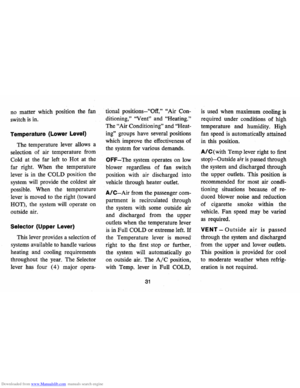
Four Season Air Conditioning
equipped cars have no kick panel
vents since the vents are a part of
the air conditioning system.
Page 32 of 84

Downloaded from www.Manualslib.com manuals search engine Heater
The windshield defrosting and
defogging system assists in provid
ing good visibility through desig
nated areas of the windshield under
most inclement weather conditions.
For immediate operation of the
vehicle, the windshield should be
scraped clear.
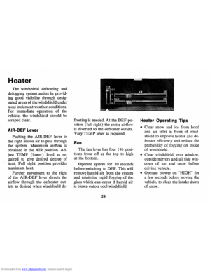
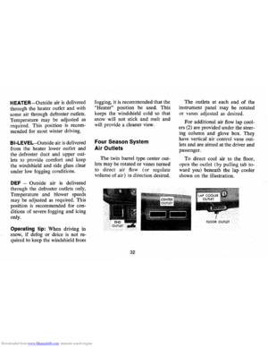
AIR-DEF Lever
Pushing the AIR-DEF lever to
the right allows air to pass through
the system. Maximum airflow
is
obtained in the AIR position. Ad
just
TEMP (lower) level as re
quired to give desired degree of
heat. Full right position provides
maximum heat.
Further movement to the right
of the AIR-DEF lever directs the
airflow through the defroster out
lets as desired when windshield de-frosting
is needed. At the DEF po
sition (full right) the entire airflow
is diverted to the defroster outlets.
Vary
TEMP lever as required.
Fan
The fan lever has four (4) posi
tions from off at the top
to high
at the bottom.
Operate system for
30 seconds
before switching to DEF. This will
remove humid air from the system
and minimize rapid fogging of the
glass which can occur if humid air
is blown onto a cool windshield.
29
Heater Operating Tips
• Clear snow and ice from hood
and air inlet
in front of wind
shield to improve heater and de
froster efficiency and reduce the
probability of fogging on inside
of windshield.
• Clear windshield, rear window,
outside mirrors and all side win
dows of ice and snow before
driving vehicle.
• Operate blower on "HIGH" for
a
few seconds before moving the
vehicle, to clear the intake ducts
of snow.
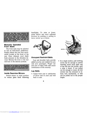
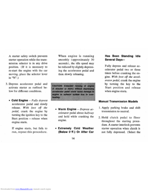
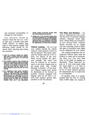
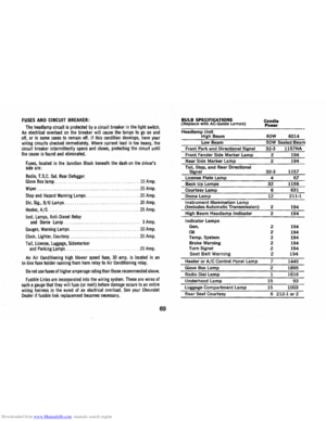
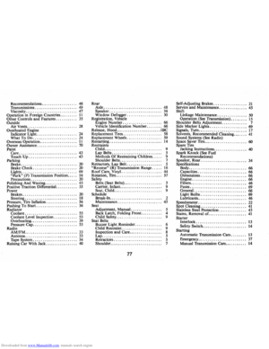
 OPTIONAL
REAR WINDOW DEFOGGER SWITCH
22
WARNIN")