1969 FORD MUSTANG spark plugs
[x] Cancel search: spark plugsPage 255 of 413

05-02-01
General Clutch Service
05-02-01
PART
5-2
General Clutch Service
COMPONENT INDEX
MODEL APPLICATION
3
a>
1
o>
il
•U
i
!-
II
CLUTCH DISC
Cleaning and Inspection
02-04
02-04
02-04
02-04
02-04
02-04
02-04
02-04
N/A
N/A
N/A
CHECKING FLYWHEEL HOUSING
ALIGNMENT
02-01
02-01
02-01
02-01
02-01
02-01
02-01
02-01
N/A
N/A
N/A
CORRECTING FLYWHEEL HOUSING
ALIGNMENT
02-03
02-03
02-03
02-03
02-03
02-03
02-03
02-03
N/A
N/A
N/A
PILOT BUSHING
Cleaning and Inspection
02-04
02-04
02-04
02-04
02-04
02-04
02-04
02-04
N/A
N/A
N/A
PRESSURE PLATE AND COVER
Cleaning and Inspection
02-04
02-04
02-04
02-04
02-04
02-04
02-04
02-04
N/A
N/A
N/A
RELEASE BEARING
Cleaning and Inspection
02-04
02-04
02-04
02-04
02-04
02-04
02-04
02-04
N/A
N/A
N/A
A page number indicates that the item is for the vehicle listed at the head of the column.
N/A indicates that the item is not applicable to the vehicle listed.
l
FLYWHEEL HOUSING ALIGNMENT
Alignment of the flywheel housing
bore and rear face with the engine
should be checked as a possible cause
of any of the following troubles- ex-
cessive transmission gear wear, ..ans-
mission jumping out of gear, especial-
ly third gear, drive line vibration, ex-
cessive pilot bushing wear, noisy re-
lease bearing, or excessive clutch spin
time.
INSPECTION
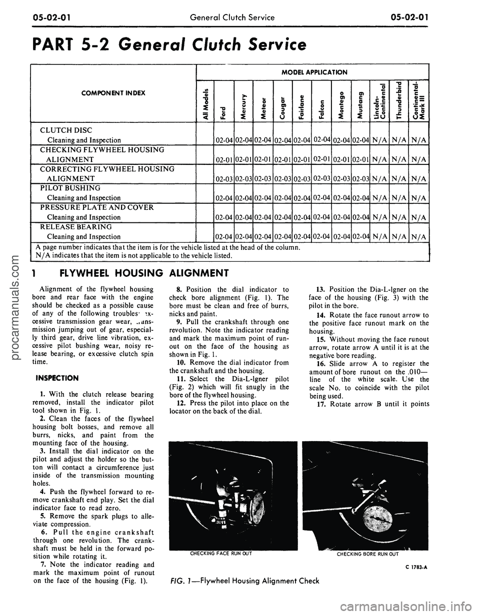
1. With the clutch release bearing
removed, install the indicator pilot
tool shown in Fig. 1.
2.
Clean the faces of the flywheel
housing bolt bosses, and remove all
burrs, nicks, and paint from the
mounting face of the housing.
3.
Install the dial indicator on the
pilot and adjust the holder so the but-
ton will contact a circumference just
inside of the transmission mounting
holes.
4.
Push the flywheel forward to re-
move crankshaft end play. Set the dial
indicator face to read zero.
5.
Remove the spark plugs to alle-
viate compression.
6. Pull the engine crankshaft
through one revolution. The crank-
shaft must be held in the forward po-
sition while rotating it.
7. Note the indicator reading and
mark the maximum point of runout
on the face of the housing (Fig. 1).
8. Position the dial indicator to
check bore alignment (Fig. 1). The
bore must be clean and free of burrs,
nicks and paint.
9. Pull the crankshaft through one
revolution. Note the indicator reading
and mark the maximum point of run-
out on the face of the housing as
shown in Fig. 1.
10.
Remove the dial indicator from
the crankshaft and the housing.
11.
Select the Dia-L-lgner pilot
(Fig. 2) which will fit snugly in the
bore of the flywheel housing.
12.
Press the pilot into place on the
locator on the back of the dial.
13.
Position the Dia-L-lgner on the
face of the housing (Fig. 3) with the
pilot in the bore.
14.
Rotate the face runout arrow to
the positive face runout mark on the
housing.
15.
Without moving the face runout
arrow, rotate arrow A until it is at the
negative bore reading.
16.
Slide arrow A to register the
amount of bore runout on the .010-
line of the white scale. Use the
scale No. to coincide with the pilot
being used.
17.
Rotate arrow B until it points
CHECKING
FACE
RUN OUT
CHECKING
BORE
RUN OUT
C
1783-
A
FIG.
1—Flywheel
Housing Alignment Checkprocarmanuals.com
Page 257 of 413

05-02-03
General Clutch Service
05-02-03
in the direction of the face runout
arrow and its center line is parallel to
the center line of the face runout
arrow.
18.
Determine the amount of the
face runout on the B arrow scale.
19.
The value of the circular line
beneath the amount of face runout
will be the desired reading. If the
reading is in excess of 0.014 inch the
housing alignment is unacceptable.
20.
Remove the Dia-L-lgner gauge
from the flywheel housing.
21.
Install the spark plugs and con-
nect the wires.
ENGINE IN VEHICLE
Since any change in face alignment
will change bore alignment, it may be
possible to correct bore alignment by
changing face alignment. Face align-
ment can be changed by shimming be-
tween the flywheel housing and en-
gine.
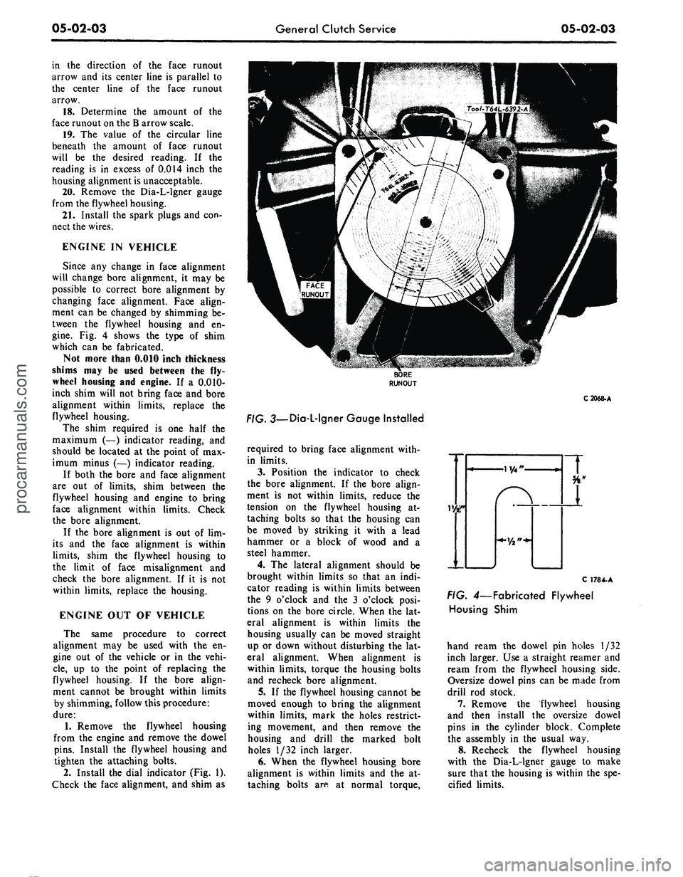
Fig. 4 shows the type of shim
which can be fabricated.
Not more than 0.010 inch thickness
shims may be used between the fly-
wheel housing and engine. If a 0.010-
inch shim will not bring face and bore
alignment within limits, replace the
flywheel housing.
The shim required is one half the
maximum (—) indicator reading, and
should be located at the point of max-
imum minus (—) indicator reading.
If both the bore and face alignment
are out of limits, shim between the
flywheel housing and engine to bring
face alignment within limits. Check
the bore alignment.
If the bore alignment is out of lim-
its and the face alignment is within
limits,
shim the flywheel housing to
the limit of face misalignment and
check the bore alignment. If it is not
within limits, replace the housing.
ENGINE OUT OF VEHICLE
The same procedure to correct
alignment may be used with the en-
gine out of the vehicle or in the vehi-
cle,
up to the point of replacing the
flywheel housing. If the bore align-
ment cannot be brought within limits
by shimming, follow this procedure:
dure:
1.
Remove the flywheel housing
from the engine and remove the dowel
pins.
Install the flywheel housing and
tighten the attaching bolts.
2.
Install the dial indicator (Fig. 1).
Check the face alignment, and shim as
C2068-A
. 3—Dia-L-lgner Gauge Installed
required to bring face alignment with-
in limits.
3.
Position the indicator to check
the bore alignment. If the bore align-
ment is not within limits, reduce the
tension on the flywheel housing at-
taching bolts so that the housing can
be moved by striking it with a lead
hammer or a block of wood and a
steel hammer.
4.
The lateral alignment should be
brought within limits so that an indi-
cator reading is within limits between
the 9 o'clock and the 3 o'clock posi-
tions on the bore circle. When the lat-
eral alignment is within limits the
housing usually can be moved straight
up or down without disturbing the lat-
eral alignment. When alignment is
within limits, torque the housing bolts
and recheck bore alignment.
5.
If the flywheel housing cannot be
moved enough to bring the alignment
within limits, mark the holes restrict-
ing movement, and then remove the
housing and drill the marked bolt
holes 1/32 inch larger.
6. When the flywheel housing bore
alignment is within limits and the at-
taching bolts are at normal torque,
C 178 4-A
FIG. 4— Fabricated Flywheel
Housing Shim
hand ream the dowel pin holes 1/32
inch larger. Use a straight reamer and
ream from the flywheel housing side.
Oversize dowel pins can be made from
drill rod stock.
7.
Remove the flywheel housing
and then install the oversize dowel
pins in the cylinder block. Complete
the assembly in the usual way.
8. Recheck the flywheel housing
with the Dia-L-lgner gauge to make
sure that the housing is within the spe-
cified limits.procarmanuals.com