1969 FORD MUSTANG Specifications part 3-13
[x] Cancel search: Specifications part 3-13Page 66 of 413

03-01-01
PART
3-1
PAGE
Suspension,
Steering, Wheels and
Tires,
General Service 03-01-01
PART
3-2
Suspension 03-02-01
PART
3-3
Automatic
Air
Leveling System ....03-03-01
PART
3-4
Automatic
Air
Leveling System
Lincoln Continental 03-04-01
PART
3-5
Steering Columns and Linkage ... 03-05-01
PART
3-6
Manual Steering 03-06-01
PART
3-7
Ford Design Non-Integral Power
Steering System
03-07-01
PART
3-8
PAGE
Ford Design Integral Power
Steering Gear 03-08-01
PART
3-9
Saginaw Design Integral Power
Steering Gear 03-09-01
PART
3-10
Ford-Thompson Power Steering
Pump 03-10-01
PART
3-11
Eaton Power Steering Pump 03-1
1-01
PART 3-12
Wheels and Tires 03-1 2-01
PART
3-13
Specifications
03-13-01
PART
3-1
Suspension,Steering, Wheels
and
Tires—General Service
COMPONENT INDEX
CASTER AND CAMBER ADJUSTMENTS
FRONT
END
INSPECTION
FRONT WHEEL ALIGNMENT CHECKS
LUBRICANT CHECKING PROCEDURE
POWER STEERING GEAR CLEANING
AND INSPECTION
POWER STEERING PRELIMINARY TESTS
POWER STEERING PUMP
Cleaning
and
Inspection
Flow
and
Pressure Tests
POWER STEERING SYSTEM FLUSHING
SHOCK ABSORBER CHECKS
STEERING WHEEL SPOKE POSITION
Adjustment
TOE-IN ADJUSTMENT
WHEEL BALANCING
MODEL APPLICATION
All
Models
01-08
01-03
01-07
01-09
01-02
01-11
01-07
01-07
01-07
Ford
01-05
01-09
01-02
01-09
Mercury
01-05
01-09
01-02
01-09
Meteor
01-05
01-09
01-02
01-09
Cougar
01-06
01-09
01-02
01-09
Fairlane
01-06
01-09
01-02
01-09
Falcon
01-06
01-09
01-02
01-09
Montego
01-06
01-09
01-02
Gl-09
Mustang
01-06
01-09
01-02
01-09
Lincoln-
Continental
01-06
01-09
01-03
N/A
Thunderbird
01-05
01-09
01-02
01-09
Continental-
Mark
III
01-05
01-10
01-03
N/A
A page number indicates that
the
item
is for the
vehicle listed
at the
head
of the
column.
N/A indicates that
the
item
is not
applicable
to the
vehicle listed.
procarmanuals.com
Page 67 of 413

03-01-02
Suspension — Steering, Wheels And Tires — General Service
03-01-02
1 TESTING
POWER STEERING-
PRELIMINARY TESTS
The following preliminary checks
should always be made before per-
forming any operations.
AIR BLEEDING
Air in the power steering system
(shown by bubbles in the fluid) should
be bled. After making sure that the
reservoir is filled to specification (the
fluid must be at normal operating
temperature when the check is made),
turn the steering wheel through its full
travel three or four times. Do not hold
the wheels against their stops. Re-
check the fluid level.
CHECK FLUID LEVEL
Run the engine until the fluid is at
normal operating temperature. Then
turn the steering wheel all the way to
the left and right several times, and
shut off the engine.
Check the fluid level in the power
steering reservoir. The level must show
on the cross hatching between the bot-
tom of the dipstick and the full mark
(Fig. 1). If the level is low, add
enough automatic transmission fluid
C1AZ-19582-A to raise the level to
the F mark on the dipstick. Do not
overfill the reservoir.
CHECK PUMP BELT
If the pump belt is broken, glazed,
or worn, replace it with a new belt.
Use only the specified type of belt.
Refer to Part 3-13 for belt adjustment
procedure.
CHECK FOR FLUID
LEAKS
With the engine idling, turn the
steering wheel from stop to stop sever-
al times. Check all possible leakage
points. Tighten all loose fittings, and
replace any damaged lines or defective
seats.
CHECK TURNING EFFORT
With the front wheels properly al-
igned and tire pressures correct, check
the effort required to turn the steering
wheel.
G 1508- A
FIG.
1—Power
Steering Pump
Dipstick
1.
With the vehicle on dry concrete,
set the parking brakes.
2.
With the engine warmed up and
running at idle speed, turn the steering
wheel to the left and right several
times to warm the fluid.
3.
Attach a pull scale to the rim of
the steering wheel. Measure the pull
required to turn the wheel one com-
plete revolution in each direction. The
effort required to rotate the steering
wheel should not exceed specifications
given in Part 3-13.
POWER STEERING PUMP FLOW
AND PRESSURE TESTS—
EXCEPT LINCOLN CONTINENTAL
AND CONTINENTAL MARK III
The power steering flow and pres-
sure tests will show whether the pump,
steering gear or power assist control
RETURN LINE
POWER
STEERING PUMP
Sr
valve is causing the trouble. Steps out-
lined below should be followed to de-
termine the cause of the trouble.
PUMP FLOW TEST
1.
Depending on the equipment
present on the vehicle (air condition-
ing, power brakes, standard transmis-
sion),
one of the following options
may be used to connect the pump
pressure and return hoses to the test
tool (T56L-3361O-D and T68L-
33610-A):
a. Disconnect the pressure and re-
turn lines at the power steering pump
(Fig. 2). Obtain a power steering re-
turn hose from stock and connect the
end with the fitting to the output fit-
ting of the tool using the
5/8-18
SAE
female, 1/4 N.P. thread male fitting
provided. The end of the stock hose
(without the fitting) should be con-
nected to the return tube of the pump.
Connect the pressure hose from the
tool to the outlet fitting of the pump.
b.
Disconnect the pressure line at
the pump and connect the pressure
line from the test tool to the outlet fit-
ting of the pump. Disconnect the re-
turn line at the gear and connect it to
the output fitting of the tool, using the
5/8-18
SAE female, 1/4 N.P. thread
male fitting provided.
2.
After installing the lines by the
most advantageous method, proceed
as follows:
3.
Open the manual valves A and B
fully (Fig. 2).
CALIBRATED FLOW
DETERMINING ORIFICE
PRESSURE LINE
FIG. 2—Power Steering Pump Test Circuit Diagram
PRESSURE GAGE
G1611-Aprocarmanuals.com
Page 68 of 413

03-01-03
Suspension — Steering, Wheels And Tires — General Service
03-01-03
4.
Connect a tachometer, start the
engine and operate it at idle speed
until the reservoir fluid temperature
reaches 165 to 175. This temperature
must be maintained throughout the
test. Valve B may be partially closed
to create a back pressure up to 350
psi to hasten the temperature rise. The
reservoir fluid must be at the proper
level.
5.
With the engine operating at rec-
ommended idle rpm and fluid temper-
ature noted in Step 4, close the manu-
al valve B. The minimum acceptable
pressure reading is 620 psi.
6. If the pressure gauge reading is
below the minimum specification, the
pump is at fault and should be re-
paired with necessary parts.
7.
If the reading is at or above the
minimum specification, the pump flow
is normal. Open manual valve B and
proceed to the Pump Fluid Pressure
Test.
PUMP FLUID
PRESSURE TEST
1.
Keep the lines and tools con-
nected as in the Pump Flow Test.
2.
With manual valves A and B
opened fully, operate the engine at
recommended idle speed (Fig. 2).
Close manual valve A, then manual
valve B. Do not keep both valves
closed for more than 5 seconds as this
would abnormally increase the fluid
temperature and cause undue pump
and/or gear wear.
3.
With the valves fully closed, the
pressure gauge should read 1000 psi
minimum for Ford, Mercury, Meteor
or Thunderbird and 750 psi minimum
for Cougar, Fairlane, Falcon, Monte-
go or Mustang.
4.
If the pressure gauge reading is
below the minimum specification, the
pump is at fault and should be re-
paired with necessary parts.
5.
If the pressure gauge reading is
at or above the minimum specifica-
tions,
the pump is normal and the
power steering gear or power assist
control valve is at fault.
FLUID PRESSURE TEST-
LINCOLN CONTINENTAL AND
CONTINENTAL MARK III
The pressure testing gauge set, tool
T56L-33610-D, requires modification
to make it adaptable for installation
in the power steering hydraulic sys-
tem. The parts required and the modi-
fication procedure are as follows:
OWER STEERING
PRESSURE LINE
INVERTED FLARE
CONNECTOR
%* TUBE x VA" PIPE
FLARED FEMALE COUPW
%' TUBE x VA" PIPE
G1544.A
FIG. 3—Modified Pressure Gauge
Assembly
a. Power Steering Pressure Line
(refer to the appropriate Parts Catal-
og).
b.
Inverted Flare Connector (3/8
inch OD Tube x 1/4 inch Pipe
Thread).
c. Inverted Flare Connector (5/16
inch OD Tube x 1/4 inch Pipe
Thread).
d. Flared Tube Female Coupling
(3/8 inch OD Tube x 1/4 inch Pipe
Thread).
The connectors and the coupling are
standard-type fittings and can be pur-
chased locally.
e. To modify tool T56L-33610-D,
remove the hose from the hand shut-
off valve block. Install the 3/8 inch x
1/4 inch inverted flare connector in
the valve block, and assemble the
pressure line to the connector (Fig. 3).
Assemble the 3/8 x 1/4 inch coupling
and the 5/16-inch connector to the
free end of the hose leading to the.
pressure gauge.
1.
To check the pump pressure, dis-
connect the front and rear sections of
the pressure line over the number 6
cylinder. Connect the modified pres-
sure-testing gauge assembly, tool
T56L-3361O-D, between the two sec-
tions.
2.
Make sure the hand-valve at the
gauge is fully opened. Start the engine
and cycle the steering gear from stop
to stop to warm up the fluid. Check
the fluid level in the reservoir and add
fluid, if necessary.
3.
Turn the steering wheel to the
full right and full left turn positions
and observe the gauge readings.
Hold the wheels in this position
only long enough to obtain an accu-
rate reading. Do not exceed 5 seconds.
The gauge should read between
1120 and 1250 psi. If the pressure is
less than 1120 psi, close the valve at
the gauge and note the pump pressure.
If it is low with the valve closed, it in-
dicates that the pump is not operating
properly. If the pressure goes up with
the valve closed, it indicates that the
low pressure in the system must be
due to internal leakage in the power
unit, providing all connections are
tight.
4.
Remove the pressure testing
gauge set, and connect the pressure
line at the steering gear. Fill and bleed
the system.
FRONT WHEEL ALIGNMENT
CHECKS
Do not attempt to check and adjust
front wheel alignment without first
making a preliminary inspection of
the front-end parts. Refer to Section
3.
Check all the factors of front wheel
alignment except the turning angle
before making any adjustments. The
turning angle should be checked only
after caster, camber, and toe-in have
been adjusted to specifications.
The front wheel alignment specifica-
tions given in Part 3-13, are correct
only when the vehicle is at curb load.
Before checking or adjusting the
alignment factors, the suspension
alignment spacers must be installed to
obtain the curb Height.
EQUIPMENT INSTALLATION
Equipment used for front wheel
alignment inspection must be accu-
rate.
Whenever possible, front wheel
alignment checks should be performed
on stationary wheel aligning equip-
Too/
- T65P3000-A or S
FIG. 4—Typical Front Alignment
Spacer Installation—Cougar,
Fairlane, Falcon,
Montego,
Mustangprocarmanuals.com
Page 70 of 413

03-01-05
Suspension — Steering, Wheels And Tires — General Service
03-01-05
type of equipment is used, follow the
installation and inspection instructions
provided by the equipment manufactu-
rer.
CASTER
Check the caster angle at each front
wheel.
The caster is the forward or rear-
ward tilt of the top of the wheel
spindle (Fig. 12). If the spindle tilts to
the rear, caster is positive. If the
spindle tilts to the front, caster is neg-
ative. The correct caster angle, or tilt,
is specified in Part 3-13.
On Mustang, Cougar, Fairlane,
Falcon and Montego vehicles, the
maximum caster difference for check-
ing purposes must not exceed one de-
gree.
If setting is necessary, then the
maximum difference must not exceed
1/2 degree. On all other vehicles, the
maximum caster difference must never
exceed 1/2 degree.
CAMBER
Check the camber angle at each
front wheel.
Camber is the amount the front
wheels are tilted at the top (Fig. 12).
If a wheel tilts outward, camber is
positive. If a wheel tilts inward, cam-
ber is negative. The correct camber
angle, or outward (positive) tilt is
specified in Part 3-13.
On Mustang, Cougar, Fairlane,
Falcon and Montego vehicles, the
maximum camber difference for
checking purposes must not exceed
one degree. If setting is necessary,
then the maximum difference must
not exceed 1/2 degree. On all other
vehicles, the maximum camber differ-
ence must never exceed 1/2 degree.
TOE-IN
Alignment height spacers should not
be used to check and adjust toe-in.
Toe-in should only be checked and ad-
justed after the caster and camber
have been adjusted to specifications.
Check the toe-in with the front
wheels in the straight-ahead position.
Run the engine so that the power
steering control valve will be in the
center (neutral) position (if so
equipped). Measure the distance be-
tween the extreme front and also be-
tween the extreme rear of both front
wheels. The difference between these
two distances is the toe-in or toe-out.
Correct toe-in, or inward pointing
of both front wheels at the front is
specified in Part 3-13.
FRONT WHEEL
TURNING ANGLE
When the inside wheel is turned 20
degrees, the turning angle of the out-
side wheel should be as specified in
Part 3-13. The turning angle cannot
be adjusted directly, because it is a re-
sult of the combination of caster,
camber, and toe-in adjustments and
should, therefore, be measured only
after these adjustments have been
made. If the turning angle does not
measure to specifications, check the
spindle or other suspension parts for a
bent condition.
ALIGNMENT
MARKS
G-1496-A
FIG. I?—Straight Ahead Position
Marks—Typical
POSITIVE
CAMBER
• •
NEGATIVE-*!
| ^*—
CASTER
ICL
OF TIRE
POSITIVE
CASTER
5r\
CA&U
ANGlE
F1216-A
FIG. 72—Caster and Camber
Angles
COMMON ADJUSTMENTS AND REPAIRS
After front wheel alignment factors
have been checked, make the neces-
sary adjustments. Do not attempt to
adjust front wheel alignment by bend-
ing the suspension or steering parts.
CASTER AND CAMBER
ADJUSTMENTS
FORD, MERCURY, METEOR,
THUNDERBIRDAND
CONTINENTAL MARK III
Caster and camber is adjusted by
loosening the bolts that attach the
upper suspension arm inner shaft to
the frame side rail, and moving the
inner shaft in or out in the elongated
bolt holes with the tool shown in Fig.
13.
The tool should be installed with
the tool pins in the frame holes and
the hooks over the upper arm inner
shaft. Then, tighten the tool hook nuts
snug before loosening the upper arm
inner shaft attaching bolts.
Caster
To adjust the caster angle, tighten
the tool front hook nut or loosen the
rear hook nut (Fig. 14) as required to
increase caster to the desired angle.
To decrease caster, tighten the tool
rear hook nut or loosen the front
hook nut as required (Fig. 14). The
caster angle can be checked without
tightening the inner shaft attaching
bolts.
Check the camber adjustment to
be sure it did not change during the
caster adjustment and adjust if neces-
FIG. 73—Camber and Caster
Adjusting Toolprocarmanuals.com
Page 72 of 413
03-01-07
Suspension — Steering, Wheels And Tires — General Service
03-01-07
upper arm shaft to the frame member
(Fig. 3, Part 3-2).
2.
Loosen the arm shaft attaching
bolts,
raise the front end of the vehicle
and lower it again. This will break the
arm shaft loose from the frame mem-
ber.
3.
With a pry bar, move the arm
shaft back into alignment with the
chalk marks made in Step 1, and
tighten the shaft attaching bolts. The
bolts should be tightened just enough
to hold the shaft in position without
preventing its being moved with the
pry bar.
Caster
1.
With the aid of a pry bar, move
the shaft in or out, as required, to
meet specifications. A movement of
approximately 3 /32 inch at either the
front or rear bolt location will change
the caster 1/2 degree. Inboard move-
ment of the front bolt, or outboard
movement of the rear bolt, will change
caster in the negative direction. Out-
board movement of the front bolt, or
inboard movement of the rear bolt,
will change caster in the positive di-
rection.
2.
When the caster is correct, tor-
que the shaft attaching bolts to speci-
fication and recheck the caster and
camber to insure that the readings
have not changed.
Camber
TURN DOWNWARD TO
INCREASE ROD LENGTH
TURN UPWARD
TO DECREASE
ROD LENGTH
TURN
DOWNWARD
TO DECREASE
ROD LENGTH
TURN UPWARD TO
INCREASE ROD LENGTH
LEFT-HAND SLEEVE
RIGHT-HAND SLEEVE
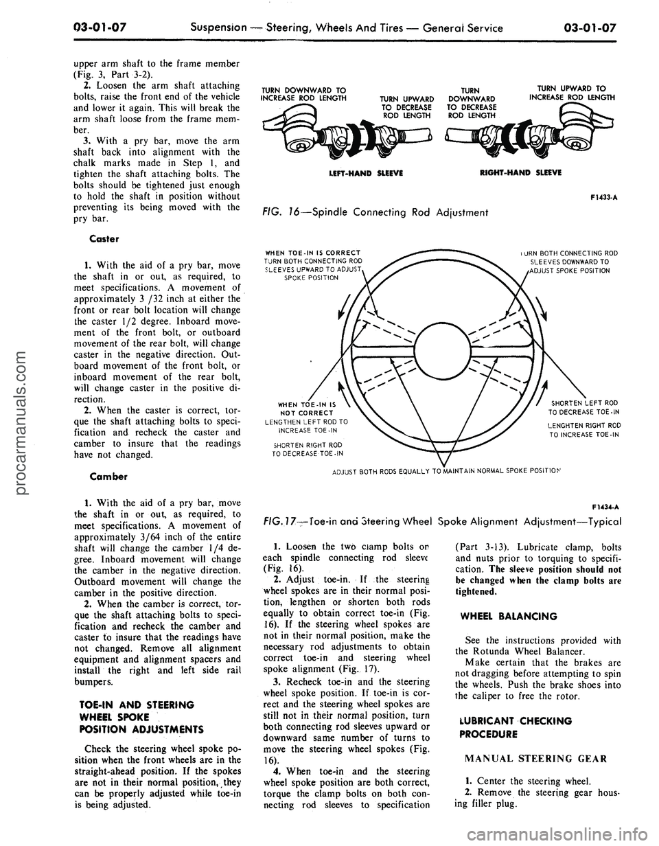
FIG. 16—Spindle Connecting Rod Adjustment
WHEN TOE-IN IS CORRECT
TURN BOTH CONNECTING ROD
SLEEVES UPWARD TO ADJUST
SPOKE POSITION
F1433-A
i URN BOTH CONNECTING ROD
SLEEVES DOWNWARD TO
ADJUST SPOKE POSITION
WHEN TOE-IN IS
NOT CORRECT
LENGTHEN LEFT ROD TO
INCREASE TOE-IN
SHORTEN RIGHT ROD
TO DECREASE TOE-IN
SHORTEN LEFT ROD
TO DECREASE TOE-IN
LENGHTEN RIGHT ROD
TO INCREASE TOE-IN
ADJUST BOTH RODS EQUALLY TO MAINTAIN NORMAL SPOKE POSITION
1.
With the aid of a pry bar, move
the shaft in or out, as required, to
meet specifications. A movement of
approximately 3/64 inch of the entire
shaft will change the camber 1/4 de-
gree.
Inboard movement will change
the camber in the negative direction.
Outboard movement will change the
camber in the positive direction.
2.
When the camber is correct, tor-
que the shaft attaching bolts to speci-
fication and recheck the camber and
caster to insure that the readings have
not changed. Remove all alignment
equipment and alignment spacers and
install the right and left side rail
bumpers.
TOE-IN AND STEERING
WHEEL SPOKE
POSITION ADJUSTMENTS
Check the steering wheel spoke po-
sition when the front wheels are in the
straight-ahead position. If the spokes
are not in their normal position, they
can be properly adjusted while toe-in
is being adjusted.
F1434-
A
f/G.77—Toe-in and Steering Wheel Spoke Alignment Adjustment—Typical
1.
Loosen the two ciamp bolts or
each spindle connecting rod sleeve
(Fig. 16).
2.
Adjust toe-in. If the steering
wheel spokes are in their normal posi-
tion, lengthen or shorten both rods
equally to obtain correct toe-in (Fig.
16).
If the steering wheel spokes are
not in their normal position, make the
necessary rod adjustments to obtain
correct toe-in and steering wheel
spoke alignment (Fig. 17).
3.
Recheck toe-in and the steering
wheel spoke position. If toe-in is cor-
rect and the steering wheel spokes are
still not in their normal position, turn
both connecting rod sleeves upward or
downward same number of turns to
move the steering wheel spokes (Fig.
16).
4.
When toe-in and the steering
wheel spoke position are both correct,
torque the clamp bolts on both con-
necting rod sleeves to specification
(Part 3-13). Lubricate clamp, bolts
and nuts prior to torquing to specifi-
cation. The sleeve position should not
be changed when the clamp bolts are
tightened.
WHEEL BALANCING
See the instructions provided with
the Rotunda Wheel Balancer.
Make certain that the brakes are
not dragging before attempting to spin
the wheels. Push the brake shoes into
the caliper to free the rotor.
LUBRICANT CHECKING
PROCEDURE
MANUAL STEERING GEAR
1.
Center the steering wheel.
2.
Remove the steering gear hous-
ing filler plug.procarmanuals.com
Page 74 of 413

03-01-09
Suspension — Steering, Wheels And Tires — General Service
03-01-09
the reading exceeds specifications
(Part 3-13), replace the upper ball
joint.
LOWER BALL JOINT
INSPECTION
Ford,
Mercury, Meteor,
Thunderbird, Lincoln Continental
and Continental Mark III
1.
Raise the vehicle and place
jacks under the lower arms as shown
in Fig. 12. This will unload the lower
ball joints.
2.
Adjust the wheel bearings as des-
cribed in Part 3-12.
3.
Attach a dial indicator to the
lower arm and position the indicator
so that the plunger rests against the
inner side of the wheel rim adjacent to
the lower ball joint.
4.
Grasp the tire at the top and
bottom and slowly move the tire in
and out (Fig. 19). Note the reading
(radial play) on the dial indicator. If
the reading exceeds specifications
(Part 3-13), replace the lower ball
joint.
Cougar, Fairlane, Falcon,
Montego, Mustang
1.
Raise the vehicle on a frame
contact hoist or by floor jacks placed
beneath the underbody until the wheel
falls to the full down position.
2.
Ask an assistant to grasp the
lower edge of the tire and move the
wheel in and out.
3.
As the wheel is being moved in
and out, observe the lower end of the
spindle and the lower arm.
4.
Any movement between the
lower end of the spindle and the lower
arm indicates ball joint wear and loss
of preload. If any such movement is
observed, replace the lower arm.
During the foregoing check, the
upper ball joint will be unloaded and
may move. Disregard all such move-
ment of the upper ball joint. Also, do
not mistake loose wheel bearings for a
worn ball joint.
POWER STEERING GEAR
CLEANING
Disassembly and assembly of the
steering gear and. the sub-assemblies
must be made on a clean workbench.
As in repairing any hydraulically op-
erated unit, cleanliness is of utmost
importance. The bench, tools, and
parts must be kept clean at all times.
Thoroughly clean the exterior of the
unit with a suitable solvent and, when
necessary drain as much of the hy-
draulic fluid as possible. Handle all
parts very carefully to avoid nicks,
burrs,
scratches and dirt, which could
make the parts unfit for use.
Do not clean, wash or soak seals in
cleaning solvent.
INSPECTION
1.
Check the sector shaft contact
surface in the cover for wear. If worn,
replace the cover.
2.
Inspect the input shaft bearing
for cracked races and the balls for
looseness, wear, pitting, end play or
other damage. Check the fit of the
bearing on the input shaft. Replace
the bearing, if required.
3.
Inspect the valve housing for
wear, scoring or burrs.
4.
Inspect the tube seats in the
pressure and return ports in the valve
body for nicks, etc. If necessary, re-
move and replace.
5.
Check the sector shaft contact
surface in the housing for wear. If
worn, replace the bushing or the hous-
ing.
6. Check all fluid passages for ob-
struction or leakage.
7.
Inspect the steering gear housing
for cracks, stripped threads, and mat-
ing surfaces for burrs. Inspect the pis-
ton bore of the housing for scoring or
wear. If necessary, replace the hous-
ing.
8. Check the input shaft bearing
after installation to be sure that it ro-
tates freely.
9. If the valve spool is not free in
the valve housing, check for burrs at
the outward edges of the working
lands in the housing and remove with
a hard stone. Check the valve spool
for burrs and if burrs are found, stone
the valve in a radial direction only.
Check for freedom of the valve again.
10.
Check the piston rack teeth and
sector shaft teeth for nicks and burrs.
FLUSHING THE POWER
STEERING SYSTEM—ALL EXCEPT
LINCOLN CONTINENTAL AND
CONTINENTAL MARK III
Should it be necessary to replace an
inoperative power steering pump, the
need for flushing the steering system
is required when installing the new
pump.
1.
Remove the power steering pump
and remove the pulley as outlined in
Part 3-10.
2.
Install the pulley on a new
pump. Install the pump and connect
only the pressure hose to the pump
(Part 3-10).
3.
Place the fluid return line in a
suitable container and plug the reser-
voir return pipe.
4.
Fill the reservoir with lubricant
(C1AZ-19582-A).
5.
Disconnect the coil wire to pre-
vent the engine from starting and raise
the front wheels off the ground.
6. While approximately two quarts
of steering gear fluid are being poured
into the reservoir, turn the engine over
using the ignition key, at the same
time cycle the steering wheel from
stop to stop.
7.
As soon as all of the lubricant
has been poured in, turn off the igni-
tion key, and attach the coil wire.
8. Remove the plug from the reser-
voir return pipe, and attach the return
hose to the reservoir.
9. Check the reservoir fluid level; if
low, add fluid to the proper level. Do
not overfill.
10.
Lower the vehicle.
11.
Start the engine and cycle the
steering from stop to stop to expel
any trapped air from the system.
POWER STEERING PUMP—ALL
EXCEPT LINCOLN
CONTINENTAL AND
CONTINENTAL MARK III
CLEANING
Wash all parts (except seals) in a
Naptha or Chlorinated-type solvent
and dry with compressed air.
Punch or Rod
RELIEF VALVE PLUNGER
G1607-A
FIG.
20—Cleaning Pump Relief Valveprocarmanuals.com
Page 96 of 413

03-02-20
Suspension
03-02-20
hub and rotor on the spindle. Position
the caliper over the rotor and install
the attaching bolts. Torque the bolts
to specification (Part 3-13). Install the
wheel and tire on the hub and adjust
the wheel bearings as outlined in Part
3-12 .
7.
Install the hub cap or wheel
cover. Then, remove the support stand
and lower the vehicle.
8. Check caster, camber, and toe-in
(Part 3-1) and adjust as necessary.
COUGAR, FAIRLANE,
FALCON, MONTEGO,
MUSTANG
Drum Brakes
Removal
1.
Position a support between the
upper arm and frame as shown in
Figs.
8 and 9; then, raise the vehicle
and position safety stands.
2.
Remove the hub cap or wheel
cover.
3.
Remove the grease cap from the
hub;
then, remove the adjusting nut,
washer, and outer bearing cone and
roller assembly.
4.
Pull the wheel, hub, and drum
assembly off the wheel spindle.
5.
Remove the brake backing plate
from the spindle. Support the plate to
prevent damage to the brake hose.
6. Disconnect the spindle connect-
ing rod end from the spindle arm
using Tool 3290-C.
7.
Remove the cotter pins from
both ball joint stud nuts, and loosen
the nuts one or two turns. Do not re-
move the nuts from the studs at this
time.
8. Position the ball joint remover
tool between the upper and lower ball
joint studs (Fig. 10). The tool should
seat firmly against the ends of both
studs and not against the stud nuts.
9. Turn the tool with a wrench until
the tool places the studs under consid-
erable tension, and, with a hammer,
hit the spindle smartly near the studs
to break them loose in the spindle. Do
not loosen the studs in the spindle
with tool pressure alone.
10.
Remove the stud nuts and re-
move the spindle from both studs.
Installation
1.
Position the spindle on the lower
ball joint stud and install the stud nut
(Fig. 25).
2.
Raise the lower suspension arm
and guide the upper ball joint stud
into the spindle. Install the stud nut.
3.
Torque the upper stud nut and
then the lower stud nut to specifica-
tion. Continue to tighten both nuts
until the cotter pin holes and slots line
up.
Install new cotter pins.
4.
Connect the spindle connecting
rod end to the spindle arm.
5.
Install the brake backing plate
on the spindle, and torque the bolts to
specification.
6. Install the wntel and drum and
adjust the wheel bearing (Part 3-12).
7.
Remove the safety stands, and
lower the vehicle.
8. Remove the support from be-
tween the upper arm and frame.
9. Check and, if necessary, adjust
caster, camber, and toe-in.
Disc Brakes
Removal
1.
Remove the hub cap or wheel
cover, and remove the wheel and tire
from the hub.
2.
Remove two bolts attaching the
caliper to the spindle. Remove the cal-
iper from the rotor and wire it to the
underbody to prevent damage to the
brake hose.
3.
Remove the grease cap from the
hub,
then, remove the adjusting nut,
washer, and outer bearing cone and
roller assembly.
4.
Pull the hub and rotor assembly
off the wheel spindle.
5.
Remove the three caliper shield
attaching bolts and remove the shield.
6. Disconnect the spindle connect-
ing rod end from the spindle arm
using Tool-3290-C.
7.
Remove the cotter pins from
both ball joint stud nuts, and loosen
the nuts one or two turns. Do not re-
move the nuts from the studs at this
time.
8. Position the ball joint remover
tool between the upper and lower ball
joint studs (Fig. 10). The tool should
seat firmly against the ends of both
studs and not against the stud nuts.
9. Turn the tool with a wrench until
the tool places the studs under consid-
erable tension, and, with a hammer,
hit the spindle smartly near the studs
to break them loose in the spindle. Do
not loosen the studs in the spindle
with tool pressure alone.
10.
Position a floor jack under the
lower suspension arm.
11.
Remove the upper and lower
ball joint stud nuts; lower the jack
and remove the spindle.
Installation
1.
Position the spindle on the lower
ball joint stud and install the stud nut
(Fig. 25). Torque the nut to specifica-
tion and install the cotter pin.
2.
Raise the lower suspension arm,
and guide the upper ball joint stud
into the spindle. Install the stud nut.
3.
Torque the nut to specifications
and install the cotter pin. Then, re-
move the floor jack.
4.
Connect the spindle connecting
rod end to the spindle arm and install
the attaching nut. Torque the nut to
specification and install the cotter pin.
5.
Position the caliper splash shield
to the spindle and install the attaching
bolts and nuts. Torque the nuts and
bolts to specification.
6. Install the hub and rotor on the
spindle.
7.
Position the caliper to the rotor
and spindle and install the attaching
bolts.
Torque the bolts to specification
and install the safety wire.
8. Install the wheel and tire on the
hub and adjust the wheel bearing
(Part 3-12).
9. Install the hub cap or wheel
cover.
10.
Before driving the vehicle,
pump the brake pedal several times to
obtain normal brake lining-to-rotor
clearance and restore normal brake
pedal travel.
LINCOLN CONTINENTAL
Removal
1.
Raise the vehicle. Place a sup-
port under each side rail to the rear of
the lower arm in the lifting pad area.
2.
Remove the wheel and tire from
the hub.
3.
Remove 2 bolts and washers that
attach the caliper to the spindle. Re-
move the caliper from the rotor and
wire it to the underbody to prevent
damage to the brake hose.
4.
Remove the hub and rotor from
the spindle.
5.
Remove the splash shield and
gasket from the spindle.
6. Disconnect the spindle arm con-
necting rod from the spindle arm with
Tool 3290-C. See Fig. 23.
7.
Remove the cotter pins from
both ball joint stud nuts. Loosen the
nuts one to two turns.procarmanuals.com
Page 101 of 413

03-02-25
Suspension
03-02-25
pivot bolts and nuts to specification
(Part 3-13).
5.
Connect the track bar to the
frame bracket with a new nut and
bolt. Torque the nut to specification
(Part 3-13).
6. Remove the alignment spacers
and jack stands and lower the vehicle.
REAR SUSPENSION-
UPPER ARM
FORD, MERCURY,
METEOR, THUNDERBIRD,
CONTINENTAL MARK HI
Removal
1.
Raise the vehicle and support the
frame side rails with jack stands.
2.
Support the rear axle, then dis
connect the track bar from the frame
bracket.
3.
Lower the axle and support axle
under differential pinion nose, as well
as under axle.
4.
Remove the nut, bolt and two
washers that attach the upper arm to
the axle housing. Disconnect the arm
from the housing.
5.
Remove the nut and bolt that se-
cures the upper arm to the crossmem-
ber and remove the arm.
Installation
1.
Hold the upper arm in place on
the crossmember and install a new at-
taching bolt, a new lockwasher and a
new nut. Do not tighten the nut at this
time.
2.
Secure the upper arm to the axle
housing with a new attaching bolt,
two washers and a new nut. Do not
tighten the nut at this time.
3.
Install alignment spacers be-
tween the rear axle housing and
frame.
4.
Connect the track bar to the
frame bracket with a new nut and
bolt. Torque the nut to specifications.
5.
Torque the upper arm front nut
to specification. Remove the align-
ment spacers and the jack stands.
6. Adjust the pinion angle and tor-
que the rear nut to specification.
7.
Lower the vehicle.
TRACK BAR
FORD, MERCURY,
METEOR, THUNDERBIRD,
CONTINENTAL MARK HI
1.
Raise the vehicle on an axle con-
tact hoist.
FRONT PIVOT BOLT
LOWER ARM
REAR PIVOT BOLT NUT
F1439-A
FIG. 33—Rear Suspension Lower Arm Installed
Tool-T64K-5781-B4 (Thrust
Washer)
FIG. 34—Rear Spring Front Bushing Removal—Typical
F 1485. A
2.
Remove rubber cover at axle at-
tachment on track bar.
3.
Remove the nut and washer at-
taching the track bar to the upper arm
bracket and disengage the track bar
from the mounting stud (Fig. 33).
4.
Remove the nut and bolt attach-
ing the track bar to the frame side rail
and remove the track bar.
5.
Position the track bar to the
frame side rail and install a new at-
taching bolt and new nut.
6. Position the track bar on the
upper arm bracket mounting stud and
install a new washer and a new at-
taching nut. Torque the track bar at-
taching bolt and nuts to specification
(Part 3-13). Lubricate rubber cover
with synthetic rubber lubricant and in-
sert over end of stud onto washer.
Then, lower the vehicle.
REAR SPRING AND/OR BUSHING
COUGAR, FAIRLANE,
FALCON, MONTEGO,
MUSTANG
Removal
1.
Raise the vehicle on a hoist and
place supports beneath the underbody
and under the axle.
2.
Disconnect the lower end of the
shock absorber from the spring clip
plate and push the shock out of the
way. Remove the supports from under
the axle.
3.
Remove the spring clip plate
nuts from the U-bolts; then, remove
the plate (Fig. 31). Raise the rear axle
just enough to remove the weight from
the spring.
4.
Remove the two attaching nuts,
and rear shackle bar, and the two
shackle inner bushings.procarmanuals.com