03-02-08
Suspension
03-02-08
IN-VEHICLE ADJUSTMENTS AND REPAIRS
HOISTING INSTRUCTIONS
Damage to steering linkage compo-
nents and front suspension struts may
occur if care is not exercised when po-
sitioning the hoist adapters of 2 post
hoists prior to lifting the vehicle.
If a 2 post hoist is used to lift the
vehicle, place the adapters under the
lower arms or the No. 1 crossmember.
Do not allow the adapters to contact
the steering linkage. If the adapters
are placed under the crossmember, a
piece of wood (2 x 4 x 16 inches)
should be placed on the hoist channel
between the adapters. This will pre-
vent the adapters from damaging the
front suspension struts.
UPPER BALL JOINT
REPLACEMENT
FORD, MERCURY,
METEOR, THUNDERBIRD,
CONTINENTAL MARK III
1.
Raise the vehicle high enough to
provide working space, and place a
support under the lower arm. If a
chain hoist or a jack that has a nar-
row contact pad is to be used on the
bumper to raise the vehicle, distribute
the load along the bumper by using a
steel plate 3 or 4 inches long as a con-
tact pad to prevent damaging the
bumper.
2.
Remove the wheel and tire.
3.
Drill a
1/8-inch
hole through
each upper ball joint retaining rivet.
Using a large chisel, cut off the rivets.
4.
Remove the upper arm suspen-
sion bumper.
5.
Remove the cotter pin and nut
from the upper ball joint stud.
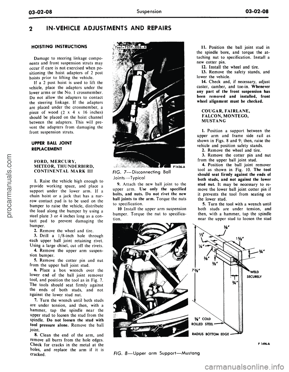
6. Place a box wrench over the
lower end of the ball joint remover
tool, and position the tool as in Fig. 7.
The tools should seat firmly against
the ends of both studs, and not
against the lower stud nut.
7.
Turn the wrench until both studs
are under tension, and then, with a
hammer, tap the spindle near the
upper stud to loosen the stud from the
spindle. Do not loosen the stud with
tool pressure alone. Remove the ball
joint.
8. Clean the end of the arm, and
remove all burrs from the hole edges.
Check for cracks in the metal at the
holes,
and replace the arm if it is
cracked.
F1436-A
FIG. 7—Disconnecting Ball
Joints—Typical
9. Attach the new ball joint to the
upper arm. Use only the specified
bolts,
and nuts. Do not rivet the new
ball joints to the arm. Torque the nuts
to specification.
10 Install the upper arm suspension
bumper. Torque the nut to specifica-
tion.
11.
Position the ball joint stud in
the spindle bore, and torque the at-
taching nut to specification. Install a
new cotter pin.
12.
Install the wheel and tire.
13.
Remove the safety stands, and
lower the vehicle.
14.
Check and, if necessary, adjust
caster, camber, and toe-in. Whenever
any part of the front suspension has
been removed and installed, front
wheel alignment must be checked.
COUGAR, FAIRLANE,
FALCON, MONTEGO,
MUSTANG
1.
Position a support between the
upper arm and frame side rail as
shown in Figs. 8 and 9; then, raise the
vehicle and position safety stands.
2.
Remove the wheel and tire.
3.
Remove the cotter pin and nut
from the upper ball joint stud.
4.
Position the ball joint remover
tool as shown in Fig. 10. The tool
should seat firmly against the ends of
both studs, and not against the lower
stud nut. It may be necessary to re-
move the lower ball joint cotter pin if
it prevents the tool from seating on
the lower stud.
5.
Turn the tool with a wrench until
both studs are under tension, and
then, with a hammer, tap the spindle
near the upper stud to loosen the stud
F 1496-A
FIG. 8—Upper arm Support—Mustangprocarmanuals.com