Page 620 of 659

ACCESSORIES 15-11
12 VOLTS D.C.
ELECTRIC BRAKE
RELEASE
IGNITION
SWITCH
ENGINE
VACUUM
TRANSDUCER
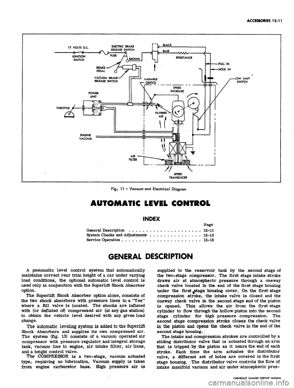
Fig.
11 - Vacuum and Electrical Diagram
AUTOMATIC LEVEL CONTROL
INDEX
Page
General Description . . 15-11
System Checks and Adjustments 15-13
Service Operation . 15-15
GENERAL DESCRIPTION
A pneumatic level control system that automatically
maintains correct rear trim height of a car under varying
load conditions, the optional automatic level control is
used only in conjunction with the Superlift Shock Absorber
option.
The Superlift Shock Absorber option alone, consists of
the two shock absorbers with pressure lines to a "Tee"
where a ill valve is located, the shocks are inflated
with (or deflated of) compressed air (at any gas station)
to obtain the vehicle level desired with any given load
change.
The automatic leveling system is added to the Superlift
Shock Absorbers and supplies its own compressed air.
The system (fig. 13) consists of a vacuum operated air
compressor with pressure regulator,
and
integral storage
tank, vacuum line to engine, air intake filter, air lines,
and a height control valve.
The COMPRESSOR is a two-stage, vacuum actuated
type, requiring no lubrication. Vacuum supply is taken
from engine carburetor base. High pressure air is
supplied to the reservoir tank by the second stage of
the two-stage compressor. The first stage intake stroke
draws air at atmospheric pressure through a oneway
check valve located in the end of the first stage housing
under the first ^tagei housing cover. On the first stage
compression stroke, the intake valve is closed and the
oneway check valve in the second stage end of the piston
is opened. This allows the air from the first stage
cylinder to flow through the hollow piston into the second
stage cylinder for jhigh pressure compression. The
second stage compression stroke closes the check valve
in the piston and opeijis the check valve in the end of the
second stage housing.
The intake and compression strokes are controlled by a
sliding distributor valive that is actuated through an arm
that is tripped by the piston as it nears the end of each
stroke. Each time the arm actuates the distributor
valve, a different set of holes are covered in the first
stage housing. The distributor valve controls the flow of
intake manifold vacuum and air under atmospheric pres-
CHEVROLET CHASSIS SERVICE MANUAL
Page 640 of 659
SPECIFICATIONS
13
ENGINE ELECTRICAL
SECTION
6Y
BATTERY
Battery Model
Application
Ground
Plates
Cranking Power @ 0°F. (Watts)
1980032*
153L-4,
194, 230,
250L-6 & 283
V-8
Neg.
54
2300
1980030*
327,
350, 396
& 427 V-8
Neg.
66
2900
1980036*
396 & 427 V-8
w/AC & M-40
Trans.
Neg.
66
3150
*65° Side Recess and One Piece Cover Construction
GENERATOR
Generator Model
Application
Field Amp.
Draw
Hot
Output
—
Amps.
Cold Output -
Volts
1100695
Chevy n
Exc.
V-8,
Sta. Wgn.
or AC
2.2-2.6
32
14
1100693
Chevy n
w/V-8,
Camaro,
CheveUe,
Chevrolet
* and
Corvette
w/AC
2.2-2.6
37
14
1100696
Chevy II
w/AC &
RPO
K-66
2.2-2.6
42
14
1100742
Chevrolet
w/AC &
Turbo-
Hydramatic
2.8-3.2
63
14
110075Q
AUA/C
except*
w/RPO
M-40
and
Chevy H
2.2-2.6
61
14
1117754
Optional
3.7-4.4
62
14
1117777
Optional
4.14-4.62
62
14
CHEVROLET CHASSIS SERVICE MANUAL
Page 652 of 659

SPECIFICATIONS 25
BODY AND CHASSIS ELECTRICAL
SECTION
12
LAMP USAGE
CANDLE
POWER
BULB
NUMBER
Headlamp Unit
Chevrolet, Chevelle & Corvette
Outer - High Beam
Outer - Low Beam
Inner -• High Beam only
Chevy H
High Beam . .
Low Beam
Parking Lamp and Directional Signal
All Exc. Camaro
Camaro
Tail, Stop and Directional Signal (Exc. Bel Air)
Backing Lamp ••...,
Instrument Illumination Lamps
Chevrolet & Camaro ,
Chevelle and Chevy n
Corvette
Temperature Indicator
Chevrolet & Camaro
Chevelle and Chevy II .............
Oil Pressure Indicator
Chevrolet & Camaro .............
Chevelle and Chevy II
Generator Indicator
Chevrolet & Camaro .
Chevelle and Chevy n ,
Hi-Beam Indicator
Chevrolet & Camaro <
Chevelle and Chevy II
Corvette , . • . ,
Directional Indicator
Chevrolet & Camaro
Chevelle & Chevy II . .
Corvette . .
Cigarette Lighter Lamp
Corvette .
Ignition Lock Lamp
Chevrolet . . .
Corvette . . .
Heater or A/C Control Panel
Chevrolet, Chevelle, Chevy n & Camaro . . .
Corvette . . .
Glove Box Lamps
Chevrolet, Chevelle, Chevy n & Camaro . . .
Corvette . . . . .
Dome and Courtesy Lamps
Cartridge Type (AU)
Bayonet Type (Exc. Corvette) . . .
Corvette ,
Convertible . .
37 1/2 Watts
55 Watts
37 1/2 Watts
55 Watts
45 Watts
4-32
4-32
4-32
Special Fiber
1
2
3
2
3
12
6
6
6
Optic
4002
4002
4001
6012
1157
1034-A
1157
1156
194
1895
.
1816
194
1895
194
1895
194
1895
194
1895
1445
194
1895
1816
1445
Wiring
1445
1895
1893
1895
1893
211
89,
212
90
631
CHEVROLET CHASSIS SERVICE MANUAL