1965 CHEVROLET CORVAIR instrument panel
[x] Cancel search: instrument panelPage 11 of 56
Downloaded from www.Manualslib.com manuals search engine INSTRUMENTS
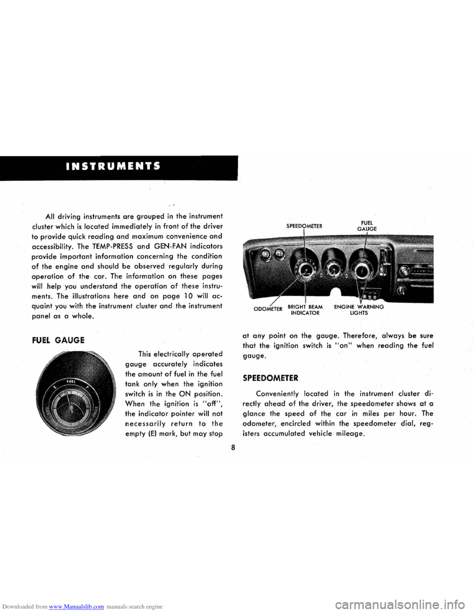
All driving instruments are grouped in the instrument
cluster
which is located immediately in front of the driver
to provide quick reading and maximum convenience and
accessibility. The TEMP-PRESS and GEN-FAN indicators
provide important information concerning the condition
of the engine and should be observed regularly during
operation of the car. The information on these pages
will help you understand the operation of these instru
ments. The illustrations here
and on page 10 will ac
quaint you with the instrument cluster and the instrument
panel as a whole.
FUEL GAUGE
This electrically operated
gauge accurately indicates
the amount of fuel in the fuel
tank only when the ignition
switch is in the ON position.
When the ignition is "off",
the indicator pointer will not
necessarily return to the
empty IE) mark, but may stop
8
at any point on the gauge. Therefore, always be sure
that the ignition switch is "on" when reading the fuel
gauge.
SPEEDOMETER
Conveniently located in the instrument cluster di
rectly ahead of the driver, the speedometer shows at a
glance the speed of the car in miles per hour. The
odometer, encircled within the speedometer dial, reg
isters accumulated vehicle mileage.
Page 14 of 56
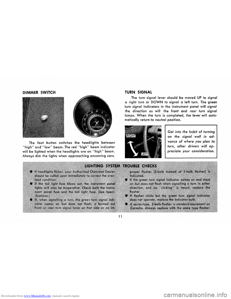
Downloaded from www.Manualslib.com manuals search engine DIMMER SWITCH
The foot button switches the headlights between
"high" and "low" beam. The red "high" beam indicator
will be lighted when the headlights are on "high" beam.
Always dim the lights when approaching oncoming cars.
11
TURN SIGNAL
The turn signal lever should be moved UP to signal
a right turn or DOWN to signal a left turn. The green
turn signal indicators in the instrument panel will signal
the direction as will the front and rear turn signal
lamps. When the turn is completed, the lever will auto
matically return to neutral position.
Get into the habit of turning
on the signal well in ad
vance of where you plan to
turn, other drivers will ap
preciate your consideration.
Page 26 of 56
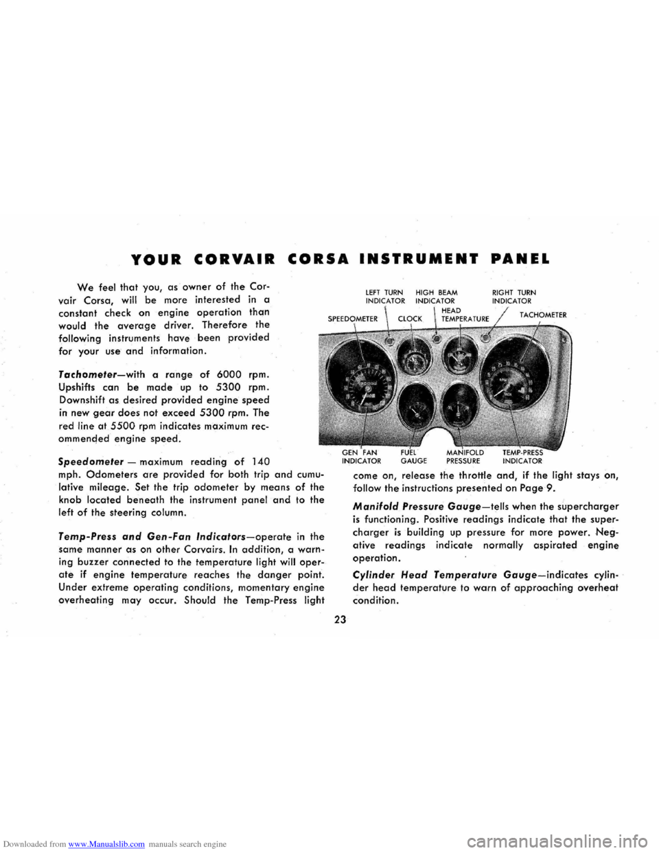
Downloaded from www.Manualslib.com manuals search engine YOUR CORVAIR CORSA INSTRUMENT PANEL
We feel that you, as owner of the Cor-
vair Corsa, will be more interested in a
constant check on
engine operation than
would the average driver. Therefore the
following instruments have been provided
for your use and information.
Tachometer-with a range of 6000 rpm.
Upshifts can
be made up to 5300 rpm.
Downshift as desired provided engine speed
in
new gear does not exceed 5300 rpm. The
red
line at 5500 rpm indicates maximum rec
ommencled
engine speed.
Speedometer -maximum reading of 140
mph. Odometers are provided for both trip and cumu
lative mileage. Set the trip odometer by means of the
knob located beneath the instrument panel and to the
left of the steering column.
Temp-Press and Gen-Fan Indicators-operate in the
same
manner as on other Corvairs. In addition, a warn
ing buzzer connected to the temperature light will oper
ate if engine temperature reaches the danger point.
Under extreme operating conditions, momentary engine
overheating may occur. Should the Temp-Press light
23
lEFT TURN HIGH BEAM INDICATOR INDICATOR
GAUGE PRESSURE
RIGHT TURN INDICATOR
come on, release the throttle and, if the light stays on,
follow the instructions presented on Page 9 .
Manifold Pressure Gauge-tells when the supercharger
is functioning. Positive readings indicate that the super
charger is building up pressure for more power. Neg
ative readings indicate normally aspirated engine
operation.
Cylinder Head Temperature Gauge-indicates cylin
der head temperature to warn of approaching overheat
condition.
Page 36 of 56
Downloaded from www.Manualslib.com manuals search engine you use an oil which, according to the label on the can
is (1) intended for service MS and (2) passes car makers'
tests or meets General Motors Standard GM 4745-M .
Oils conforming to these types contain detergent addi
tives. Your serviceman will be pleased to assist you in
selecting the proper oil for your car.
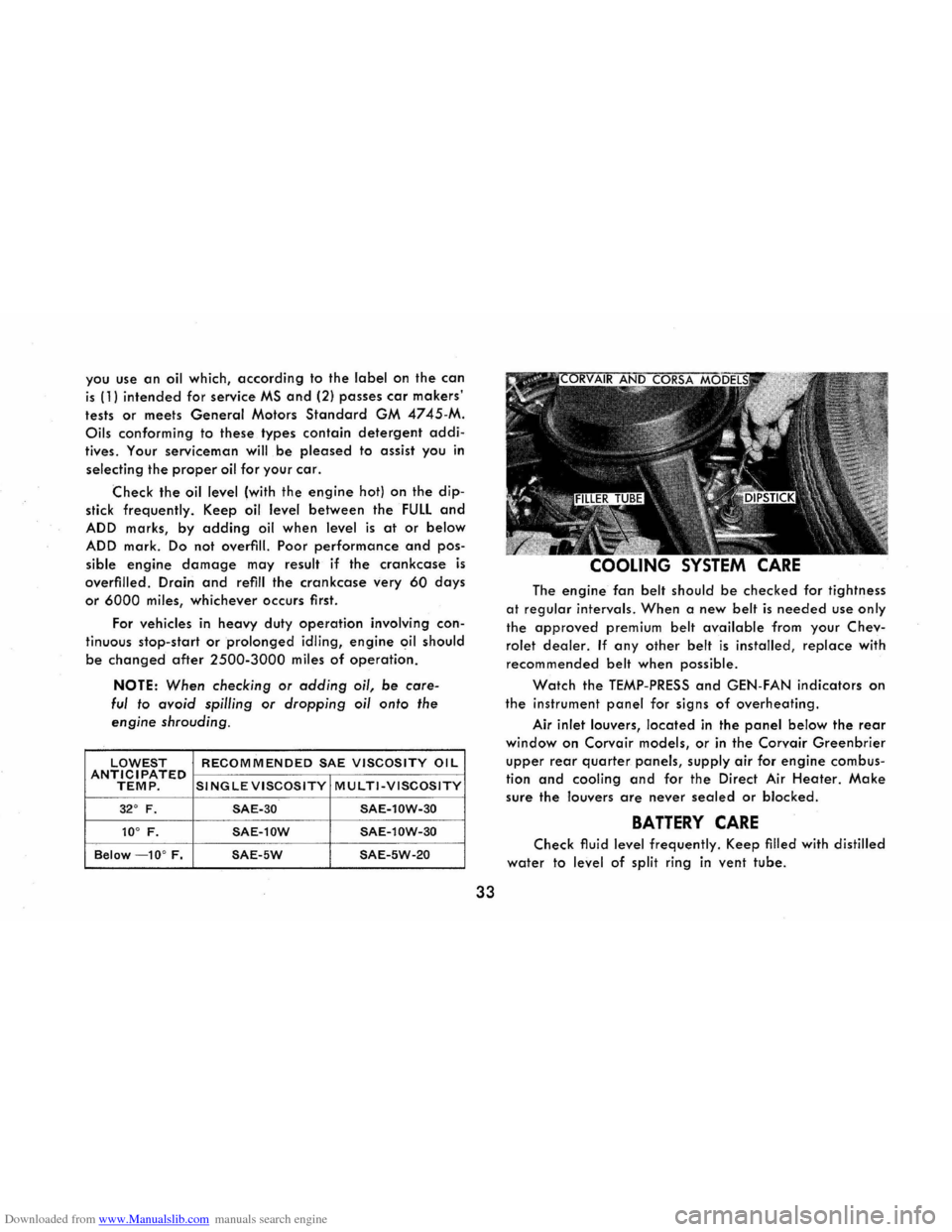
Check the oil level (with the engine hot) on the dip
stick frequently. Keep oil level between the FULL and
ADD marks, by adding oil when level is at or below
ADD mark. Do not overfill. Poor performance and pos
sible engine damage may result if the crankcase is
overfilled. Drain and refill the crankcase very 60 days
or 6000 miles, whichever occurs first.
For vehicles
in heavy duty operation involving con
tinuous stop-
start or prolonged idling, engine oil should
be changed after 2500-3000 miles of operation.
NOTE: When checking or adding oil, be care
ful to avoid spilling or dropping oil onto the
engine shrouding.
LOWEST RECOMMENDED SAE VISCOSITY OIL ANTICIPATED TEMP. SINGLE VISCOSITY MULTI-VISCOSITY
32° F. SAE-30 SAE-l0W-30
10° F. SAE-l0W SAE-l0W-30
Below -10° F. SAE-5W SAE-5W-20
33
COOLING SYSTEM CARE
The engine fan belt should be checked for tightness
at regular intervals. When a new belt is needed use only
the approved premium belt available from your Chev
rolet dealer. If any other belt is installed, replace with
recommended belt when possible .
Watch the TEMP-PRESS and GEN-FAN indicators on
the instrument panel for signs of overheating.
Air inlet louvers, located in the panel below the rear
window on Corvair models, or in the Corvair Greenbrier
upper rear quarter panels, supply air for engine combus
tion
and cooling and for the Direct Air Heater. Make
sure the louvers are never sealed or blocked.
BATTERY CARE
Check fluid level frequently. Keep filled with distilled
water to level of split ring in vent tube.
Page 48 of 56
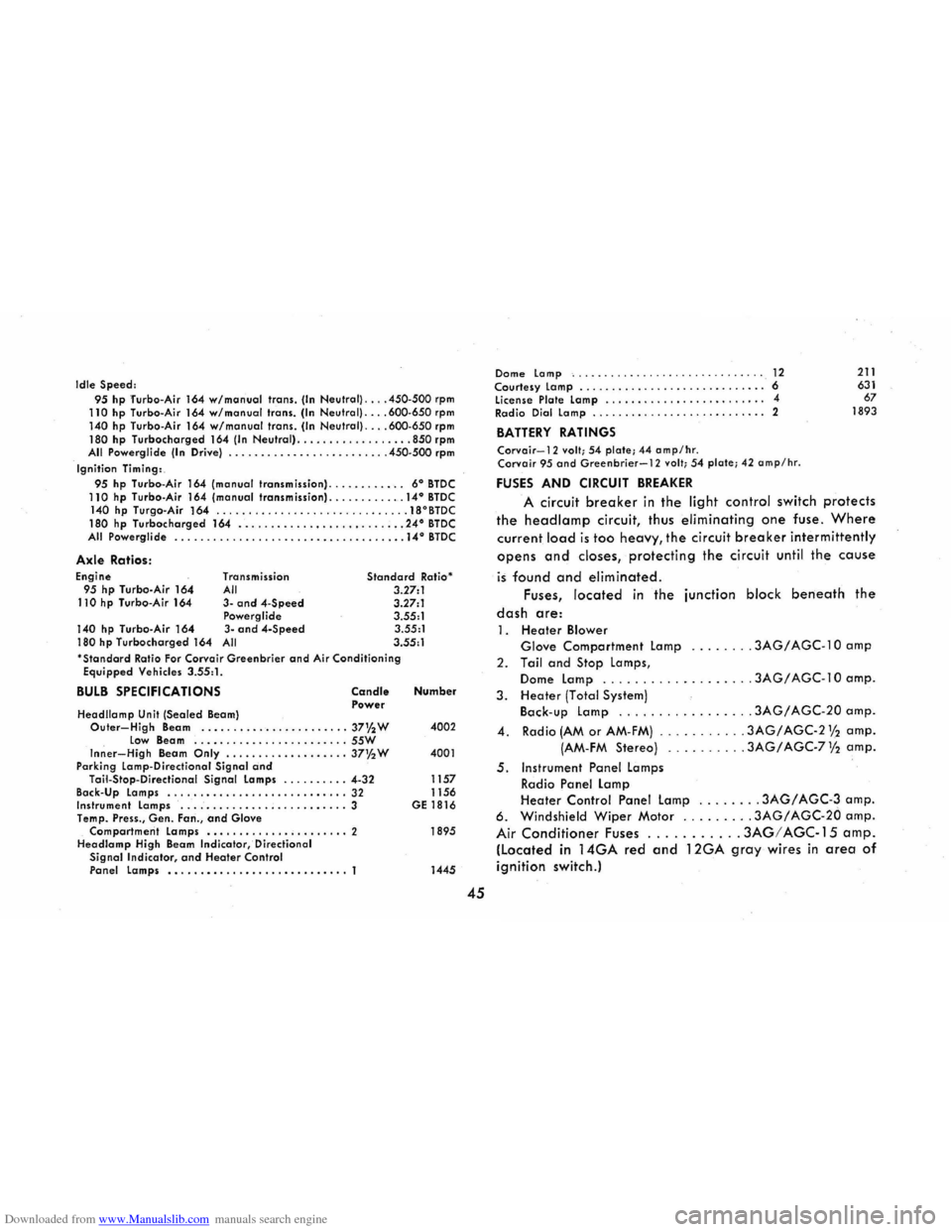
Downloaded from www.Manualslib.com manuals search engine Idle Speed: 95 hp Turbo-Air 164 w/monuol trans. (In Neutral) .... 450-500 rpm 110 hp Turbo-Air 164 w/manual trans. (In Neutral) .... 600-650 rpm 140 hp Turbo-Air 164 w/manualtrans. (In Neutral) .... 600-650 rpm 180 hp Turbocharged 164 (In Neutral) .................. 850 rpm All Powerglide (In Drive) .............. , .......... 450-500 rpm
Ignition Timing:. 95 hp Turbo-Air 164 (manual transmission) ............ 6° BTDC 110 hp Turbo-Air 164 (manual transmission) ............ 14° BTDC 140 hp Turgo-Air 164 .............................. 18°BTDC
180 hp Turbocharged 164 .......................... 24° BTDC All Powerglide ...........................••....•• . 14° BTDC
Axle Ratios: Engine 95 hp Turbo-Air 164 110 hp Turbo-Air 164
140 hp Turbo-Air 164 180 hp Turbocharged 164
Transmission All 3-and 4-Speed Powerglide
3 -and 4-Speed All
Standard Ratio "
3.27:1
3.27:1
3.55:1 3.55:1
3.55: 1 'Standard Ratio For Corvair Greenbrier and Air Conditioning Equipped Vehicles 3.55:1.
BULB SPECIFICATIONS
Headllamp Unit (Sealed Beam)
Candle Power
Outer-High Beam ......•.........•...... 37% W low Beam ....•.............•..... 55W Inner-High Beam Only ................... 37'!z W
Parking lamp-Directional Signal and Tail-Stap-D irectional Signal lamps ... ...•... 4-32
Back-Up lamps ............................ 32 Instrument lamps ....................••.... 3
Temp. Press., Gen. Fan., and Glove Compartment lamps ..•.............•..... 2 Headlamp High Beam Indicator,' Directional Signal Indicator , and Heater Control Panel lamps •.....•..................•.. 1
Number
4002
4001
1157
1156
GE 1816
1895
1445
45
Dome Lomp ' ................... .. ......... 12 Courtesy lamp .........••.................. 6 license Plate lamp .....•..............•.... 4
Radio Dial lamp ........•.......•.......... 2
BATTERY RATINGS
Corvair-12 volt; 54 plate; 44 amp/hr . Corvoir 95 and Greenbrier-12 volt; 54 plate; 42 amp/hr .
FUSES AND CIRCUIT BREAKER
211 631
67
1893
A circuit breaker in the light control switch protects
the head lamp circuit, thus eliminating one fuse. Where
current load is too heavy, the circuit breaker intermittently
opens and closes, protecting the circuit until the cause
is found and eliminated.
Fuses, located in the junction block beneath the
dash are:
1. Healer Blower
Glove Comparlment lamp ........ 3AG/ AGC-1 0 amp
2. Tail and Slop lamps,
Dome lamp ................. .. 3AG / AGC-1 0 amp.
3.
Heater (Total System) Back-up lamp ................. 3AG/ AGC-20 amp.
4. Radio (AM or AM-FM) ........... 3AG/ AGC-2 Y2 amp.
(AM-FM Stereo) .. . .... 3AG/ AGC-71/2 amp.
5. Instrument Panel lamps Radio Panel lamp Heater Conlrol Panel lamp ........ 3AG/ AGC-3 amp. 6. Windshield Wiper Molor ......... 3AG/ AGC-20 amp.
Air Conditioner Fuses ........... 3AG! AGC-15 amp. (Located in 14GA red and 12GA gray wires in area of
ignition switch.)
Page 52 of 56
Downloaded from www.Manualslib.com manuals search engine and blocked AIR CLEANER ELEMENTS. Clean and reoil the air
cleaner elements if necessary. Idle adjustment should be performed
by your Chevrolet Dealer.
If the above Fuel System checks and the checks suggested under
the Electrical System following do not correct the malfunction, it is
recommended that you turn to your Authorized Chevrolet Dealer
for further checks , adjustments or repairs.
ELECTRICAL SYSTEM
If, when the ignition key is turned to START, the engine will not
turn
over, you have good reason to suspect electrical trouble.
(F) When there .is no response at all to attempts to start the car,
check the obvious-your AUTOMATIC TRANSMISSION SElECTOR
LEVER must be in neutral position before the engine can be started.
Turning the IGNITION SWITCH rapidly back and forth several
times will sometimes correct a poor internal switch contact.
(G) The
BATTERY may be discharged. If so, lights will be dim and
the horn will have a poor tone if it will blow at all.
Usually a
garage recharge will be necessary to return the battery
to operation. Occasionally, however , a push start and a long drive
will
recharge the battery.
NOTE : If the battery is determined to be dead, and for no apparent
reason , have your Authorized Chevrolet Dealer check the
battery, the GENERATOR and the VOLTAGE REGULATOR .
GENERA TOR trouble should already have been indicated by
the indicator on the instrument panel. Never remove generator
"BAT" lead without first disconnecting battery ground cable.
49
POOR BATTERY CONNECTIONS may be suspected if the car has operated properly a short time before and now not even the horn
will operate. Check both ends of both battery cables. If the con
nections are corroded, a car may sometimes be restored to opera
tion by removing all cable ends, scraping all contacting surfaces clean with a pen knife , and reassembling . If the cables are broken, they must be replaced. The power supply should now be restored unless the battery is dead.
(H) If, however, the lights and horn work properly but the starter will still not turn over, check the STARTER connections. A "click" from the starter solenoid indicates that the wiring to the starter is properly installed . If the wiring seems to be clean and tightly installed, the trouble is probably in the starter itself and should be referred to your Authorized Chevrolet Dealer.
When the engine will "turn over" but will not start, the following
items may be checked along with Fuel System Checks listed
previously .
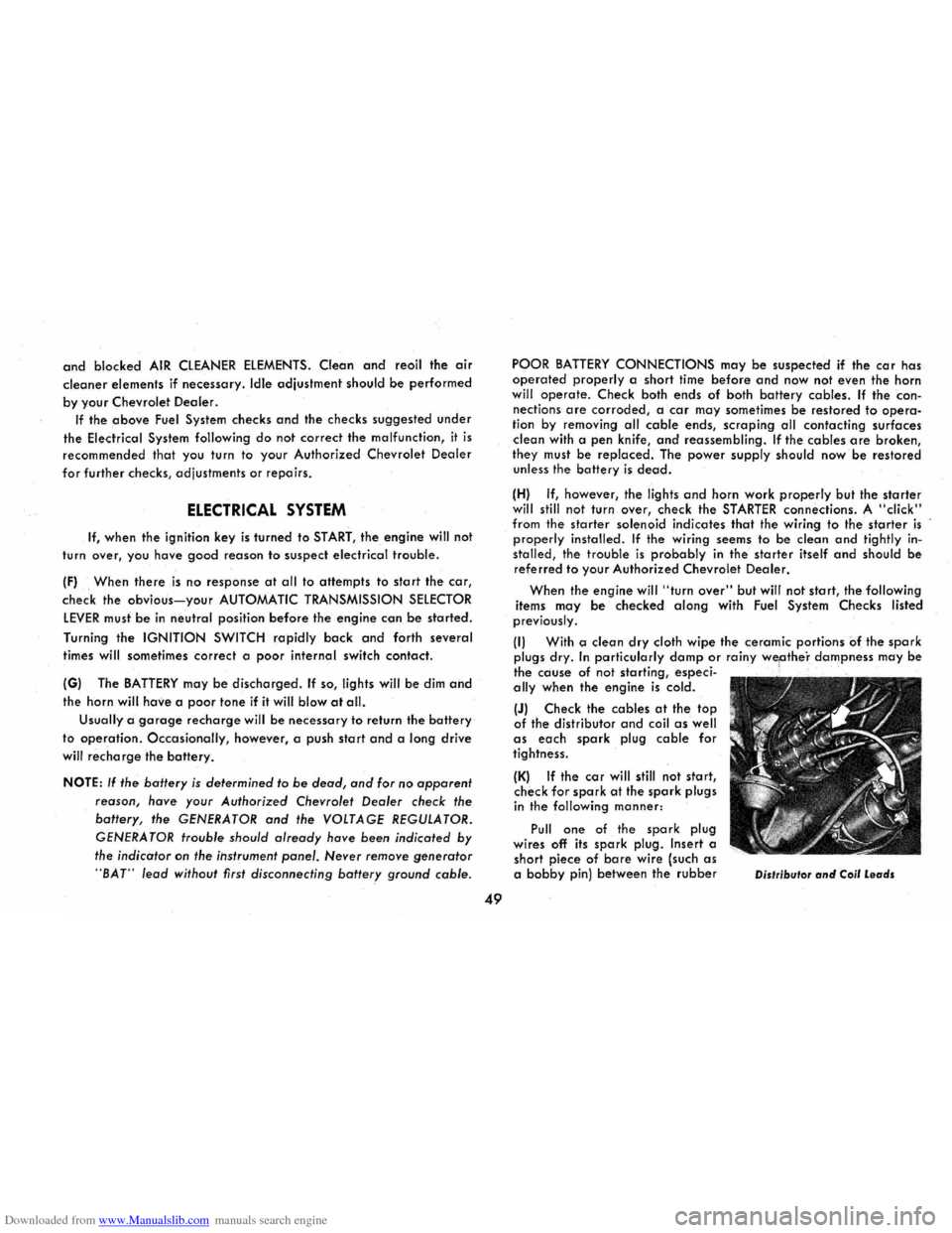
(I) With a clean dry cloth wipe the ceramic portions of the spark plugs dry. In particularly damp or rainy wellthe'r dampness may be the cause of not starting, especi-: . ally when the engine is cold.
(J) Check the cables at the top of the distributor and coil as well as each spark plug cable for tightness.
(K) If the car will still not start, check for spark at the spark plugs in the following manner:
Pull
one of the spark plug
wires off its spark plug. Insert a
short piece of bare wire (such as a bobby pin) between the rubber Oislribulor and Coil Leads
Page 53 of 56
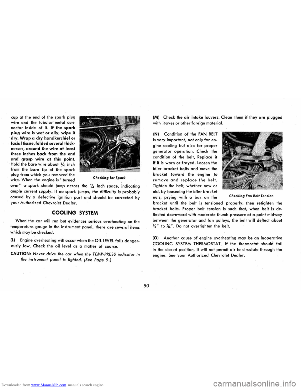
Downloaded from www.Manualslib.com manuals search engine cup at the end of the spark plug
wire
and the tubular metal con
nector inside of it. If the spark
plug wire is wet or oily, wipe it
dry. Wrap a dry handkerchief or
facial tissue, folded several thick
nesses, around the wire at least
three inches back from the end
and grasp wire at this point. Hold the bare wire about 1,4 inch
from the.
bare tip of the spark
plug from which you removed the
wir,e. When the engine is "turned Checking 'or Spark
over" a spark should jump across the 1,4 inch space, indicating
ample current supply. If no spark jumps, the difficulty is probably
caused by a defective ignition part and should be corrected by
your Authorized Chevrolet
Dealer.
COOLING SYSTEM
When the car will run but evidences serious overheating on the
temperature gauge in the instrument panel, there are several items
which may
be checked.
(L) Engine overheating will occur when the OIL LEVEL falls danger
ouslylow. Check the oil level as a malter of course.
CAUTION: Never drive the car when the TEMP-PRESS indicator in
the instrument panel is lighted. (See Page 9.)
50
(M) Check the air intake louvers . Clean them if they are plugged
with leaves or other foreign material.
(N) Condition of the FAN BELT
is very important, not only for en
gine cooling but
also for proper
generator operation. Check the
condit ion of the belt. Replace
it
if it is worn or frayed. Loosen the
idler
bracket bolts and move the
bracket toward the engine to
remove and replace the belt.
Tighten the belt, whether new or
old, by loosening the idler bracket nuts, prying with a bar on the Checking Fan Bel' Tension
bracket until the belt is tensioned properly, then retighten the
bracket bolts. Proper belt tension is such that, when belt is de
flected downward with moderate thumb pressure at a point midway
between the
generator and fan pulleys, the belt will deflect about
%" to X6". Do not overtighten the belt.
(0) Another cause of engine overheating may be an inoperative
COOLING SYSTEM THERMOSTAT. If the thermostat should fail
i n the closed position, it will not permit
air to circulate through the
engine. See your Authorized Chevrolet Dealer.