Page 17 of 52

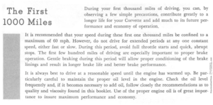
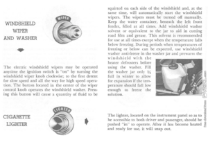
WINDSHIELD
WIPER
AND WASHER
..
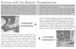
The electric windshield wipers may be operated
anytime the ignition switch is "on" by turni ng the
\-vindshield wip er knob clockwise; to the first detent
for slow speed
and all the way for high speed opera
tion. 'The button located in the center of the wiper
contro l knob operates the windshield washer. Press
ing this button will cause a quantity of fluid to be
CIGARETTE
LIGHTER • squ
irted on ea
ch sid e of the windshield and, at the
same time, will autom atically star t the windshi eld
w ipers. The wipers must be turned off manually.
Keep the water container , beneath the l eft front
fender, filled
at all times. Add windshield washer solvent or equ ivalent to the jar to aid in c utting
road film and grease . This so lve nt is recomm ended for lise at all times except when th e temperature falls
below freezing. During periods when temperawres of freezing or below can be expected, use windshield
washer anti-freeze in the washer jar and prewarm the windshield with the heater defrosters before
us ing the washer. Fill
the was her jar on l), %
full in win ter to allow for expa nsion if the temperature should fall low enou gh to freeze the
so lution.
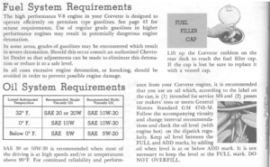
The light e r. located on the instrument panel so as to
be accessible to both dri
ver and passenger, should be pushed "in" to operate. After it has become hea ted and ready for use, it will snap out.
Page 18 of 52

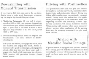
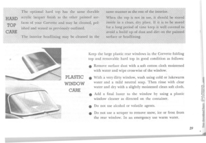
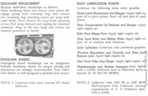
The retractable dual headlights contribute much to the long, low appearance 01 your Corvette and also
serve to protect the headlights when not in use . Two switches are necessary for headlight operation.
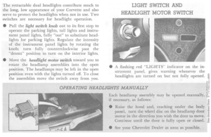
• Pull
the light switch knob out to its first stop to operate the parking lights, tail lights and instru· ment panel lights, fully "out" to substitute head·
lights lor parking lights. Regulate th e intensity 01 the instrument panel lights by rotating the
knob; turn fully counterclockwise past the
"detent" position
to turn on the interior lights.
• Move
the headlight motor switch toward you to
rotate the head lamp assemblies into the open
position. The headlamps may be lelt in the open
position even WiLh the lights turned off. To close
the assemblies move the switch away from you.
LIGHT SWITCH AND
HEADLIGHT MOTOR SWITCH
• A flashing red "LIGHTS" indicator on the in·
strument panel, gives warning whenever the
headlights are
turned on but not fully opened.
OPERATING HEADLIGHTS MANUALLY
Each headlamp assembly may be opened manuaJly, if necessary, as follows:
• Raise
the hood and, reaching under the body panel, turn the wheel disc on the headlamp door motor in the direction you wish the door to move. Continue until the door is fully open or closed .
• See
your Chevrolet Dealer as sOOn as possible.
Page 19 of 52

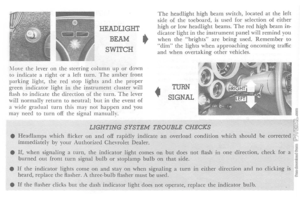
HEADLIGHT
BEAM •
SWITCH
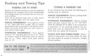
i\fove the lever on t h e steering column up or down to indicate a right o r a left turn. The amber front parking light, the red stop lights and the proper green indicator light in the instrument cluster will
flash to indicate the d irection of the turn. The lever
wi ll normally return to neutral; but in the event of
a wide gradual turn this may not happen and you
may nee d to turn off the signa l manually.
The headlight high beam switch, located at the left
side of the toeboard. is used for selection of either high or low headlight beams. The red high beam indicator light in the instrument p a nel will remind you when the "brights" are being used. Remember to "dim" the lights when approaching oncoming traffic and when overtaking other vehicles .
•
TURN
SIGNAL
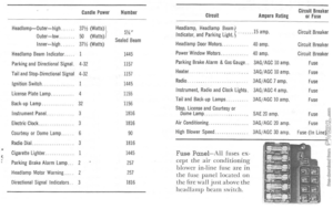
LIGHTING SYSTEM TROUBLE CHECKS • Headlamps which Hickel' on and off rapidly indicate an overload condition which should be corrected immediately by your Authorized Chevrolet Dealer.
•
If, when signaling a turn, the indicator light comes on but does not Hash in one direction, check for a burned out front turn signal bulb or stoplamp bulb on that side.
•
If the indicator lights come on and stay on when signaling a turn in either direction and no clicking is heard, replace the flasher. A three-bulb Aasher must be used.
•
If the Hasher clicks but the dash indicator light does not operate, replace the indicator bulb.
Page 20 of 52

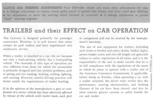
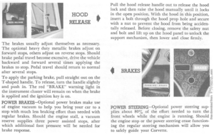
HOOD
RELEASE •
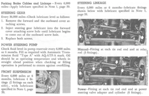
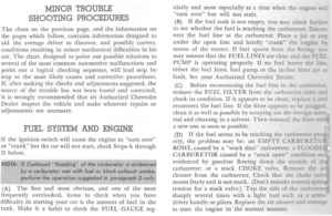
The brakes usually adjust themselves as necessary. The optional heavy duty metallic brakes adjust on forward stops, others adjust on reverse stops. Should
brake pedal travel become excessive, drive the vehicle
back ward
and forward several times applying the
brakes to stop. Pedal travel should return to normal after several stops. To apply the parking brake, pull straight out on the T-shaped handle. To release, turn the handle slightly and push in. The red "BRAKE" warning light in the instrument cluster will remain on when the brake is applied and the ignition key is on. POWER BRAKES-Optional power brakes make use of engine vacuum to help you bring your car to a stop with much less braking effort than needed with regular brakes. Should the engine stall. a vacuum
reserve supplies three power assisted stops, after
which additional foot pressure will be needed for
brake response.
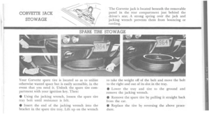
Pull the hood release handle out to release the hood lock and then raise the hood manually until it locks
in the open position . With the hood in this position, insert a bolt through the hood prop hole and secure
with a nut to prevent the hood from being acciden
tally released. Before closing, remove the safety nut
and bolt and lift up on the hood panel to unlock the
support mechanism . then lower and close firmly.
• BRAKES
POWER STEERING-Optional power steering sup
plies about 80 % of the effort needed to turn the front wheels while the engine is running. Should the engine stop or the power steering cease function ing the regular steering mechanism will allow you
to safely guide your Corvette.
Page 21 of 52

HEATER AND DEFROSTER Two knobs allow full control of your Corvette Heater.
AIR·PULL-DEF-This control supplies outside air to the Heater when pulled out to the "detent" position and diverts the air-flow to the defroster duct when pulled fully out. This knob must be pulled out to "detent" or further before operating the healer.
FAN-TEMP-PULL-Heater output air temperature is regulated as this knob is pulled out. Maximum heat is obtained in the fully out posi
tion . Rotate the knob to obtain low, medium or high fan speed.
HEATER OPERATING TIPS
• Always brush snow from the air inlet in front of the windshield before operating the heater. elf less than maximum heat is desired, operate FA~ on low or medium speed and regulate the air temperature by moving the FAN·TEMP·PULL knob partially in. • Operate the heater for several minutes before turning on the defroster. This will clear the system of moisture and help
prevent windshield fogging.
VENTILATION
DURING •
WARM WEATHER
•
Air vents in each side panel, operated by vent knobs
on either side of the steering column, admit outside
air from the vent grille in the cowl.
•
Pull AIR·PULL-DEF knob lO detent or fully open, to admit outside air through the heater.
• Additional ventilation
is available on sport coupe
models by means of luggage compartment exhaust fan. To operate the fan , pull the knob located next to the left air vent control. This fan will not oper
ate when the heater fan is being used.
Page 22 of 52

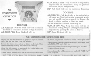
AIR
CONDITIONER OPERATION
..
HEATING
AIR-PULL -FAN-Pull this knob fully out and rotate the knob to obtain low, medium or high fan speed.
AIR COND- PULL -Keep this knob fully in.
COOL IN-HOT PULL-Vary this knob as required to regulate the air temperature. Fully out provides maximum output temperature.
DEF-Pull knob fully out for maximum defrosting.
COOLING AIR-PULL-FAN-Push knob fully in for re-circulation of inside air. Vary knob setting to provide a mixture of outside and recirculated air. Rotate the knob to obtain medium or high fan speed.
AIR COND-PULL-Pull this knob fully out. COOL IN -HOT PULL-Keep this knob fully in for maximum cooling. Output air temperature may be regulated b y pulling the knob as desired. DEF-Keep this knob fully in.
AIR CONDITIONER OPERATING
TIPS During the first few minutes of operation open a window to Jet out hot air, then close the window.
Rotate the three dash outlets to direct cooled air. Close center outlet by rotating the deflector all the way.
Close the side outlets by means
of the knobs below and several inches inboard of the outlets.
off knobs, to provide additional cooled ai.r for your feet.
For maximum cooling under extreme heat conditions, push AIR-PULL-FAN knob fully in.
For cooling under moderate temperatures, pull AIR·PULL· FAN knob out to detent.
For cooling under mild temperatures pull AIR·PULL·FAN Rotate covers, located about six inches inboard of the shut knob fully out.
RUN T!iE SYSTEM FOR FIVE MINUTES EVERY WEEK TO LUBR.JCATE SSALS AND MOVING PARTS.
Page 23 of 52

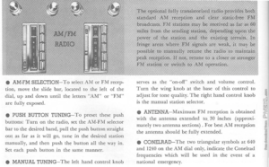
• AM-FM SELECTION-To select AM or FM recep
ti on, move the sli de bar, located to the left of the
dia l, up and down until
the letters "AM" or "FT\1" are fully exposed.
• PUSH BUTTON TUNING
-To preset these push
buttons: Turn on the radio, set the AM-FM selector
bar to the desired band, pull the push button stra ight out as far as i t will go, tune in the desir ed station manually, and then push the button all the way in.
Set each push button in the same manner.
• MANUAL TUNING-
The left hand control knob
The optional 'fully ttansis'toriz~,d standaTd AM reception clear
broadcasts. FM stations nla y pe
mpes from. th,e ,endil)g station, .dc~p'~*dlil)J~.~I!l<'l'!;'~l1li,l power of the station and the
fringe areas where FM signals are weak, it may be possi
ble to manually retune the radio to mair,ltain
peak reception. lf nOt, retune to
serves as the "on-off" switch
and volume control. Turn the wing knob at the base of this contro l to
adjust for tone quality . T he right hand control knob is the manual station selector.
• ANTENNA
-Maximum FM recept io n is obtained
wi th the antenna extended to .. 30 inches (app roxi
mately two antenna sections) . For best AM reception
the antenna should be fully extend ed.
• CONELRAD- T h e t
wo triangular symbols a t 640 and 1240 on the AM dial only, indicate the Cone lrad
freq uencies which will be used in the event of a
nationa l em ergency .
Page 24 of 52

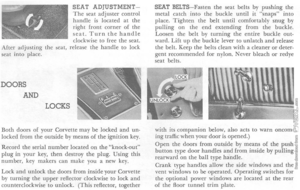
SEAT ADjUSTMENTThe seat adjuster control handle is located at the right front corner of the seat. Turn the handle clockwise to free the seat. After adjusting the seat, release the handle to lock
seat into place.
DOORS
AND
LOCKS
Both doors of your Corvette may be locked and un· locked from the outside by means of the ignition key.
Record the serial number located on the "knock·out" plug in your key, then destroy the plug. Using this number, key makers can make you a new key.
Lock and unlock the doors from inside your Corvette by turning the upper reflector clockwise to lock and counterclockwise to unlock. (This reflector, together
SEAT BELTS-Fasten the seat belts by pushing the metal catch into the buckle until it "snaps" into place. Tighten the belt until comfortably snug by pulling on the end extending from the buckle.
Loosen the belt by turning the entire buckle out· ward. Lift up the buckle lever to unlatch and release
the belt. Keep the belts clean with a cleaner or deter· gent recommended for nylon. Never bleach or redye
seat belts.
w
ith its companion below, also acts to warn oncoming traffic when your door is opened.) Open the doors from outside by means of the push bu tton type door handles and from inside by pulling rearward on the ball type handle .
Crank type handles allow the side windows and the vent windows to be operated. Operating switches for
the optional power windows are located at the rear o f the floor tunnel trim plate.