1953 JEEP DJ fuel consumption
[x] Cancel search: fuel consumptionPage 30 of 376

c
TUNE-UP
meter during this
test
Connect the red lead
tc*
dis
tributor
primary
lead at the coil as shown in Fig.
C-21.
Connect black lead to the ground.
Turn
ignition switch on; with
engine
stopped, observe
dwell
meter. If the meter reads zero,
crank
the
engine
a fraction of a revolution to
close
the
breaker
points.
Distributor
resistance is normal, if dwell meter
pointer is within range of
black
bar. Distributor resistance is high, if
dwell
meter pointer is not
within
the black bar.
Remove test lead from
distri
butor terminal of coil and
connect
to
each
of the
following points to determine
where
the excessive resistance is:
Distributor
primary
terminal
Distributor
primary
terminal in the distributor
Breaker
point bracket
Ground
side of points
Distributor
housing
Where
a noticeable change occurs in the meter
reading
in
these
steps, make the necessary correc
tion and repeat the
test.
C-l 7. Distributor
Point
Dwell
Using
a dwell tester, connect red
lead
to the
distri
butor terminal at coil. Connect black lead to
ground.
Set selector switch to the number of
cylin
ders in the
engine
being tested. Operate
engine
speed at specified rpm. and
note
readings. Cam
dwell
angle must be 30° for the Dauntless V-6
Delco equipped engine, 29° ±: 3° Prestolite equipped
engine
and 42° for the
Hurricane
F4 engine. If the dwell reading is not to specifications,
trouble could be improper point spacing, point
rubbing,
defective block or breaker arm, or mis
aligned and worn distributor cam.
Adjust
dwell
as shown in Fig. C-14 for the Delco equipped
Dauntless V-6 engine. For cam dwell adjustment
of the Prestolite equipped V6 and
Hurricane
F4 engine, refer to Par. C-10,
step
a.
Dwell
variation is determined by noting any
dwell
change as the
engine
is operated at different
speeds.
Excessive
variation indicates a change in point opening that can result from shaft or bushing wear,
or
from the distributor plate shifting because of
wear
or
looseness.
Measure
dwell variation at idle speed, using same
test
hookup for checking dwell. Increase speed to 1750 rpm.;
note
dwell reading.
Then
slowly reduce
speed to idle while observing dwell meter. Dwell
variation
should not exceed 3°. If dwell variation
exceeds
3°
between
idle speed and 1750 rpm.,
probable wear in the distributor shaft, bushings, or
breaker
plate is indicated. Distributor should then be checked more thoroughly.
C-l8. Check Ignition Wires
and
Connections
Examine
and clean the insulation on all ignition
wires
and check all connections. Wires should be
firm,
flexible, and free from roughness and minute
cracks.
Bend wires to check for brittle,
cracked,
or
loose
insulation. Since defective insulation
will
per
mit
crossfiring or missing of the engine, defective
wires
should be replaced.
C-l9. Test Ignition
Cables
To
remove cables from
spark
plugs, use
Spark
Plug
Cable
Remover
Tool
W-274.
Twist
the
boot
slightly to break the seal and, grasping the rubber
protector
boot,
lift straight up with a steady even
pull.
Do not grasp the cable and
jerk
the cable off; this
will
damage the cables. Do not use a probe
on
these
wires; puncturing them may cause a
separation in the conductor. To remove ignition cables from the distributor cap or coil tower,
loosen
the nipple first, then grasp the upper part of the nipple and the cable and gently
pull
straight up.
Test
the cable with an ohmmeter. Resistance value
per
foot
is
3000-7000
ohms. The ignition cables
can
be checked for
circuit
continuity by removing
the cable from the
spark
plug and holding the cable
end Vi" [6,35 mm.] from the engine. A strong
spark
indicates
good
conductor continuity.
When
connecting the cable to the
spark
plug, be
certain
a
good
connection is made and that the
protector
boot
fits tight on the
spark
plug. A
partially
seated cable creates an additional gap in
the
circuit
and the resulting
spark
jump
will
cause
terminal
corrosion and cable damage.
C-20. Coil
When
an ignition coil is suspected of being defec tive, it should be checked on the car. A coil may
break
down after it has reached operating tempera
ture.
It is important that the coil be at operating
temperature when
tests
are made.
Note:
The ignition coil and ballast resistor for the
V-6
engine
must be of the same manufacturer.
Ballast
resistors and ignition coils of one manufac
turer
are interchangeable with both units of the
other.
C-21.
Service Air
Cleaner
Refer
to Par.
B-2 2
for the correct service of the
air
cleaner.
C-22.
Check Fuel Lines and
Screens
Check
all fuel line connections to guard against
leakage.
Check
fuel pump filter F4
engine
and
fuel
line filter V-6 engine. Replace fuel filter if
necessary.
C-23. Check Fuel Pump a.
Fuel
pump pressure is important, for low pres
sure
will
seriously affect
engine
operation and high
pressure
will
cause excessive fuel consumption and
possibly flood the carburetor. Should there be any doubt of normal operation, check the pressure with
a
gauge
as shown in Fig.
C-2 2.
The minimum and
maximum
allowable pressures are 2% to 3% lbs. [0,176 a
0,264
kg-cm2], for the
Hurricane
F4 en
gine.
Fuel
pump pressure at carburetor (inlet) on
the Dauntless V6-225
engine
should be 3% lbs.
[0,264
kg-cm2] minimum at specified
R.P.M.
idle
with
the vapor
return
hose
squeezed off.
With
the
vapor
return
hose
open pump pressure should be
2
V2
lbs. [0,176 kg-cm2] minimum.
b.
Test for volume, as a pump may build up suffi
cient pressure but
fail
to produce sufficient volume.
Turn
down the carburetor fuel line fitting on the
pump and with the tank line connected, pump out
30
Page 34 of 376

TUNE-UP
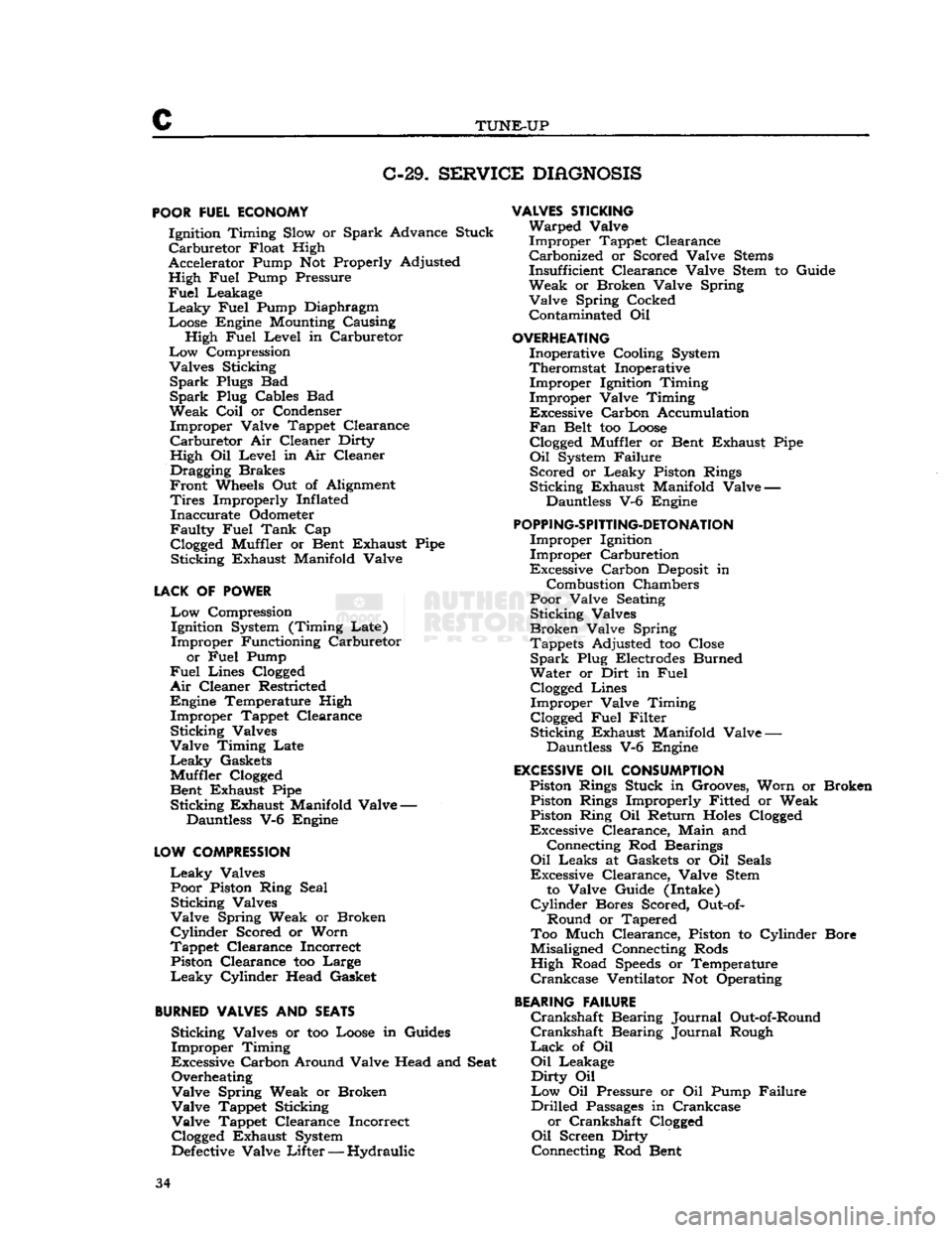
C-29.
SERVICE
DIAGNOSIS
POOR
FUEL ECONOMY Ignition Timing Slow or Spark Advance Stuck
Carburetor
Float High
Accelerator Pump Not Properly Adjusted High Fuel Pump Pressure
Fuel
Leakage
Leaky
Fuel Pump Diaphragm Loose Engine Mounting Causing High Fuel Level in Carburetor
Low
Compression
Valves Sticking
Spark
Plugs Bad
Spark
Plug Cables Bad
Weak
Coil
or Condenser Improper Valve Tappet Clearance
Carburetor
Air Cleaner Dirty
High Oil Level in Air Cleaner Dragging Brakes
Front
Wheels Out of Alignment
Tires
Improperly Inflated Inaccurate Odometer
Faulty
Fuel Tank Cap
Clogged
Muffler or Bent Exhaust Pipe Sticking Exhaust Manifold Valve
LACK
OF POWER
Low
Compression Ignition System (Timing Late)
Improper Functioning Carburetor
or Fuel Pump
Fuel
Lines
Clogged
Air
Cleaner Restricted Engine Temperature High Improper Tappet Clearance
Sticking Valves
Valve Timing Late
Leaky
Gaskets
Muffler
Clogged
Bent Exhaust Pipe Sticking Exhaust Manifold Valve —
Dauntless V-6 Engine
LOW
COMPRESSION
Leaky
Valves Poor Piston Ring Seal Sticking Valves
Valve Spring Weak or Broken
Cylinder
Scored or Worn
Tappet Clearance Incorrect Piston Clearance too Large
Leaky
Cylinder Head Gasket
BURNED
VALVES AND SEATS Sticking Valves or too Loose in Guides
Improper Timing
Excessive Carbon Around Valve Head and Seat Overheating
Valve Spring Weak or Broken
Valve Tappet Sticking
Valve Tappet Clearance Incorrect
Clogged
Exhaust System
Defective
Valve
Lifter
— Hydraulic
VALVES
STICKING
Warped Valve Improper Tappet Clearance Carbonized or Scored Valve
Stems
Insufficient Clearance Valve Stem to Guide
Weak or Broken Valve Spring Valve Spring Cocked Contaminated Oil
OVERHEATING
Inoperative Cooling System
Theromstat Inoperative Improper Ignition Timing
Improper Valve Timing
Excessive Carbon Accumulation
Fan
Belt too Loose
Clogged
Muffler or Bent Exhaust Pipe
Oil
System Failure Scored or Leaky Piston Rings
Sticking Exhaust Manifold Valve — Dauntless V-6 Engine
POPPING-SPITTING-DETONATION
Improper Ignition Improper Carburetion
Excessive Carbon
Deposit
in
Combustion Chambers
Poor Valve Seating Sticking Valves
Broken Valve Spring Tappets Adjusted too Close
Spark
Plug Electrodes Burned
Water or Dirt in Fuel
Clogged
Lines Improper Valve Timing
Clogged
Fuel Filter Sticking Exhaust Manifold Valve —
Dauntless V-6 Engine
EXCESSIVE
OIL CONSUMPTION Piston Rings Stuck in Grooves, Worn or Broken Piston Rings Improperly Fitted or Weak Piston Ring Oil Return
Holes
Clogged
Excessive Clearance, Main and
Connecting Rod Bearings
Oil
Leaks at Gaskets or Oil Seals
Excessive Clearance, Valve Stem
to Valve Guide (Intake)
Cylinder
Bores Scored, Out-of-
Round or Tapered
Too Much Clearance, Piston to Cylinder Bore
Misaligned Connecting Rods
High Road
Speeds
or Temperature
Crankcase
Ventilator Not Operating
BEARING
FAILURE
Crankshaft
Bearing Journal Out-of-Round
Crankshaft
Bearing Journal Rough
Lack
of Oil
Oil
Leakage
Dirty
Oil
Low
Oil Pressure or Oil Pump Failure
Drilled
Passages
in Crankcase or Crankshaft
Clogged
Oil
Screen Dirty
Connecting Rod Bent 34
Page 105 of 376

'Jeep'
UNIVERSAL
SERIES SERVICE
MANUAL
Dl
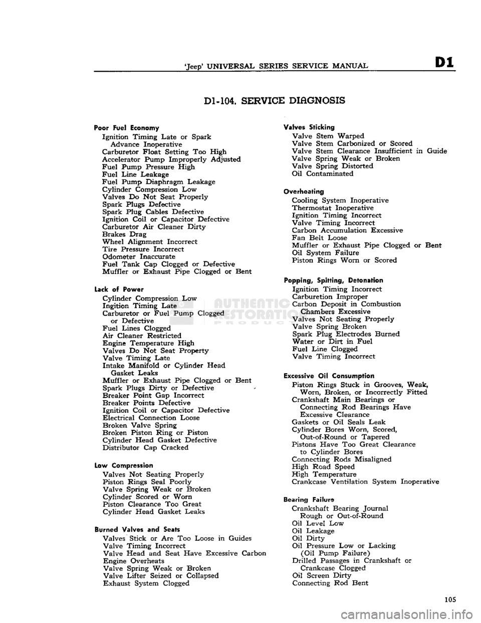
Dl-104.
SERVICE
DIAGNOSIS
Poor Fuel Economy
Ignition Timing Late or Spark Advance Inoperative
Carburetor
Float Setting Too High
Accelerator Pump Improperly Adjusted
Fuel
Pump Pressure High
Fuel
Line
Leakage
Fuel
Pump Diaphragm Leakage
Cylinder
Compression Low
Valves Do Not Seat Properly
Spark
Plugs
Defective
Spark
Plug Cables
Defective
Ignition
Coil
or Capacitor
Defective
Carburetor
Air Cleaner Dirty
Brakes
Drag
Wheel Alignment Incorrect
Tire
Pressure Incorrect Odometer Inaccurate
Fuel
Tank
Cap Clogged or
Defective
Muffler or Exhaust Pipe Clogged or Bent
Lack
of
Power
Cylinder
Compression Low
Ingitdon Timing Late
Carburetor
or
Fuel
Pump Clogged or
Defective
Fuel
Lines Clogged
Air
Cleaner Restricted
Engine Temperature High Valves Do Not Seat Property
Valve
Timing Late Intake Manifold or Cylinder Head
Gasket Leaks
Muffler or Exhaust Pipe Clogged or Bent
Spark
Plugs Dirty or
Defective
Breaker
Point Gap Incorrect
Breaker
Points
Defective
Ignition
Coil
or Capacitor
Defective
Electrical
Connection Loose
Broken
Valve Spring
Broken
Piston Ring or Piston
Cylinder
Head Gasket
Defective
Distributor Cap Cracked
Low
Compression
Valves Not Seating Properly Piston Rings Seal Poorly
Valve
Spring Weak or Broken
Cylinder
Scored or Worn
Piston Clearance Too Great
Cylinder
Head Gasket Leaks
Burned
Valves and
Seats
Valves Stick or Are Too Loose in Guides
Valve
Timing Incorrect
Valve
Head and Seat Have Excessive Carbon
Engine Overheats
Valve
Spring Weak or Broken
Valve
Lifter Seized or Collapsed
Exhaust
System Clogged
Valves Sticking
Valve
Stem Warped
Valve
Stem Carbonized or Scored
Valve
Stem Clearance Insufficient in Guide
Valve
Spring Weak or Broken
Valve
Spring Distorted
Oil
Contaminated
Overheating
Cooling System Inoperative
Thermostat Inoperative Ignition Timing Incorrect
Valve
Timing Incorrect
Carbon
Accumulation Excessive
Fan
Belt Loose
Muffler or Exhaust Pipe Clogged or Bent
Oil
System Failure
Piston Rings Worn or Scored
Popping,
Spitting,
Detonation
Ignition Timing Incorrect
Carburetion
Improper
Carbon
Deposit
in Combustion
Chambers Excessive
Valves Not Seating Properly
Valve
Spring Broken
Spark
Plug Electrodes Burned
Water or Dirt in
Fuel
Fuel
Line
Clogged
Valve
Timing Incorrect
Excessive
Oil
Consumption
Piston Rings Stuck in Grooves, Weak,
Worn,
Broken, or Incorrectly Fitted
Crankshaft
Main Bearings or
Connecting Rod Bearings Have
Excessive Clearance
Gaskets or Oil Seals
Leak
Cylinder
Bores Worn, Scored,
Out-of-Round or Tapered
Pistons Have Too Great Clearance to Cylinder Bores
Connecting Rods Misaligned High Road Speed
High Temperature
Crankcase
Ventilation System Inoperative
Bearing Failure
Crankshaft
Bearing Journal Rough or Out-of-Round
Oil
Level Low
Oil
Leakage
Oil
Dirty
Oil
Pressure Low or Lacking
(Oil
Pump Failure)
Drilled
Passages
in Crankshaft or
Crankcase
Clogged
Oil
Screen Dirty
Connecting Rod Bent 105
Page 130 of 376

E
FUEL
SYSTEM
taching screws and valve housing from the fuel
pump body.
c.
Remove the two screws in the valve housing
and
separate the filter cover and air
dome
dia
phragm.
d.
Remove the cam lever return spring, plug,
cam
lever pin, and cam lever from the pump body.
Tap
the cam lever pin out of body, using a drift
inserted through the small
hole
in the pump body.
e. Remove diaphragm from pump body.
f. Under normal service, the pump may be cleaned without further disassembly.
Note:
The oil seal (at top of spring in diaphragm
assembly) seals the spring side of the fuel
dia
phragm
from the crankcase. Any deposit, in
excess
of a few drops, of oil on the diaphragm indicates leakage past the oil seal. Be sure the seat for the
seal
in the pump body is clean and smooth.
E-63.
Fuel
Pump Cleaning and Inspection
Caution:
Do not immerse valves or diaphragm
in
cleaning solvent; wipe clean.
Clean
all metal parts of the fuel pump in solvent.
Brush
with a stiff-bristled
brush.
Dry with com
pressed
air.
Check
all parts to see that they are not
cracked
or broken and that the screw threads are
not damaged.
E-64.
Fuel
Pump Reassembly
•
Refer to Fig. E-32.
a.
Assemble the valve housing and filter cover, using a new air
dome
diaphragm. The opening
in
the air
dome
diaphragm is located over the
intake
valve. The filter cover is positioned cor
rectly
when the inlet passage in the cover aligns
with
the inlet valve. Tighten the attaching screws
alternately and securely.
b.
Lubricate
diaphragm assembly shaft, around
oil
seal, with
engine
oil. Position diaphragm as sembly on valve housing and thread all the attach ing screws through diaphragm.
(This
helps avoid
damage to the screw
holes
in diaphragm.)
c.
Place diaphragm assembly and valve housing
in
position on pump body (align marks made
before disassembly).
First
start all screws one
or
two threads; then tighten the screws alternately
and
securely.
d.
Lubricate
forked end of cam lever, pin bore
of body, and corresponding
hole
in lever, and the
pin
itself with
engine
oil.
Note:
Forked
end of lever
goes
around diaphragm
shaft. Be sure
loose
bumper washer on diaphragm shaft is on top of lever and
between
lever and fixed
washer
on shaft.
e.
Install
lever and pin. To install pin, use a drift
and
tap pin into the
hole
in the body until it hits
the
stop
on the
bottom
of the hole;
move
the lever while tapping, to align
hole
in lever with the pin;
then install plug.
Install
lever return spring.
f.
Install
a new filter bowl gasket in filter cover.
Place
bail
assembly in ears on cover and swing
to one side.
Install
spring and new filter element in
bowl and install bowl on pump. Position
bail
as
sembly under bowl; tighten retainer screw.
Caution:
Do not overtighten screw.
E-65.
Fuel
Pump Installation
a.
Make certain mating surfaces of fuel pump and
engine
cylinder case are clean. Cement a new gasket to mounting flange of fuel pump.
b.
Position fuel pump on cylinder block, so that
cam
lever of pump rests on fuel pump cam of cam
shaft. Secure pump to block with two cap screws
and
lock washers. Torque
bolts
13 to 17 lb-ft. [1,8
a
2,3 kg-m.].
c.
Connect intake and
outlet
fuel lines to fuel
pump.
E-66.
Fuel
Pump Testing
Whenever
the fuel pump is to be checked for pres
sure
or volume, follow the procedure outline in
Par.
C-23 of this manual.
Fuel
pump pressure is
important
for low pressure
will
seriously affect en
gine
operation and high pressure can cause exces
sive fuel consumption and flooding of the carbure
tor.
Should there be any doubt of normal opera
tion, check the procedure as outlined in Par. C-23.
In
addition to proper fuel pressure, volume of the
pump is also important. When testing for proper
pump pressure, be certain to also
test
for volume
as the pump may build up sufficient pressure, but
fail
to produce sufficient volume.
E-67. FUEL
PUMP
—
DAUNTLESS
V-6
ENGINE
Jeep vehicles equipped with the Dauntless V6-225
engine
have a special fuel pump which has a metering
outlet
for a vapor return system. Any
vapor
which forms is returned to the fuel tank
along with hot fuel through a separate line along
side the fuel supply line.
This
greatly reduces any
FIG.
E-33—FUEL PUMP—DAUNTLESS V-6 ENGINE
1
—Fuel
Outlet 2—Vapor
Return
3—Fuel
Inlet
130
Page 134 of 376

E
FUEL
SYSTEM
E-78. SERVICE DIHGNOSIS
Symptoms Probable Remedy
Excessive
Fuel
Consumption:
Tires
improperly inflated Inflate
Brakes
drag Adjust
Engine
operates too cold Check thermostat
Heat control valve inoperative Check thermostatic spring
Leak
in fuel line Check all connections
Carburetor
float level high. See
"Carburetor"
section
Accelerator pump not properly adjusted Adjust
Leaky
fuel pump diaphragm Replace
Loose
engine
mountings causing high carburetor fuel level Tighten Ignition timing slow or spark advance stuck See "Distributor" section
Low
compression. Check valve tappet clearance
Air
cleaner dirty
.
Remove and clean
Engine
Hesitates on Acceleration: Accelerator pump
does
not function perfectly.
...................
.Replace piston and rod or adjust
Carburetor
float level. ... .Adjust
Spark
plugs Replace or clean and adjust
Low
compression Check valves
Distributor
points—dirty or pitted Replace
Weak
condenser or coil Replace
Carburetor
jets restricted Remove and clean
Excessive
engine
heat See "Engine" section
Engine
Stalls—Won't Idle:
Improper
condition of carburetor See
"Carburetor"
section
Low
speed
jet restricted Remove and clean
Dirty
fuel sediment bowl screen Remove and clean
Air
cleaner dirty Remove and clean
Leaky
manifold or gasket Replace
Fuel
pump diaphragm porous. Replace
Loose carburetor. Tighten
flange
nuts
Water
in fuel
Drain
and clean system
Improper
ignition. .See "Distributor" section
Spark
plugs Clean and adjust
Valves
sticking.
Grind
valves 134