2024 FORD F650/750 brake light
[x] Cancel search: brake lightPage 219 of 386
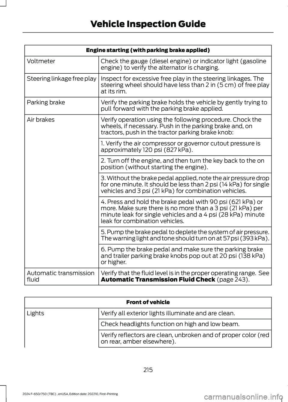
Engine starting (with parking brake applied)
Check the gauge (diesel engine) or indicator light (gasolineengine) to verify the alternator is charging.Voltmeter
Inspect for excessive free play in the steering linkages. Thesteering wheel should have less than 2 in (5 cm) of free playat its rim.
Steering linkage free play
Verify the parking brake holds the vehicle by gently trying topull forward with the parking brake applied.Parking brake
Verify operation using the following procedure. Chock thewheels, if necessary. Push in the parking brake and, ontractors, push in the tractor parking brake knob:
Air brakes
1. Verify the air compressor or governor cutout pressure isapproximately 120 psi (827 kPa).
2. Turn off the engine, and then turn the key back to the onposition (without starting the engine).
3. Without the brake pedal applied, note the air pressure dropfor one minute. It should be less than 2 psi (14 kPa) for singlevehicles and 3 psi (21 kPa) for combination vehicles.
4. Press and hold the brake pedal with 90 psi (621 kPa) ormore. Make sure there is no more than a 3 psi (21 kPa) perminute leak for single vehicles and a 4 psi (28 kPa) minuteleak for combination vehicles.
5. Pump the brake pedal to deplete the system of air pressure.The warning light and tone should turn on at 57 psi (393 kPa).
6. Pump the brake pedal and make sure the parking brakeand trailer parking brake knobs pop out at 20 psi (138 kPa)or higher.
Verify that the fluid level is in the proper operating range. SeeAutomatic Transmission Fluid Check (page 243).Automatic transmissionfluid
Front of vehicle
Verify all exterior lights illuminate and are clean.Lights
Check headlights function on high and low beam.
Verify reflectors are clean, unbroken and of proper color (redon rear, amber elsewhere).
215
2024 F-650/750 (TBC) , enUSA, Edition date: 202210, First-PrintingVehicle Inspection Guide
Page 220 of 386
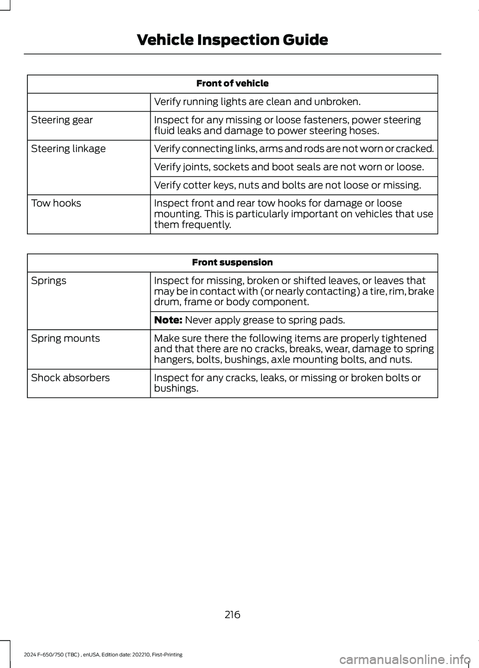
Front of vehicle
Verify running lights are clean and unbroken.
Inspect for any missing or loose fasteners, power steeringfluid leaks and damage to power steering hoses.Steering gear
Verify connecting links, arms and rods are not worn or cracked.Steering linkage
Verify joints, sockets and boot seals are not worn or loose.
Verify cotter keys, nuts and bolts are not loose or missing.
Inspect front and rear tow hooks for damage or loosemounting. This is particularly important on vehicles that usethem frequently.
Tow hooks
Front suspension
Inspect for missing, broken or shifted leaves, or leaves thatmay be in contact with (or nearly contacting) a tire, rim, brakedrum, frame or body component.
Springs
Note: Never apply grease to spring pads.
Make sure there the following items are properly tightenedand that there are no cracks, breaks, wear, damage to springhangers, bolts, bushings, axle mounting bolts, and nuts.
Spring mounts
Inspect for any cracks, leaks, or missing or broken bolts orbushings.Shock absorbers
216
2024 F-650/750 (TBC) , enUSA, Edition date: 202210, First-PrintingVehicle Inspection Guide
Page 222 of 386
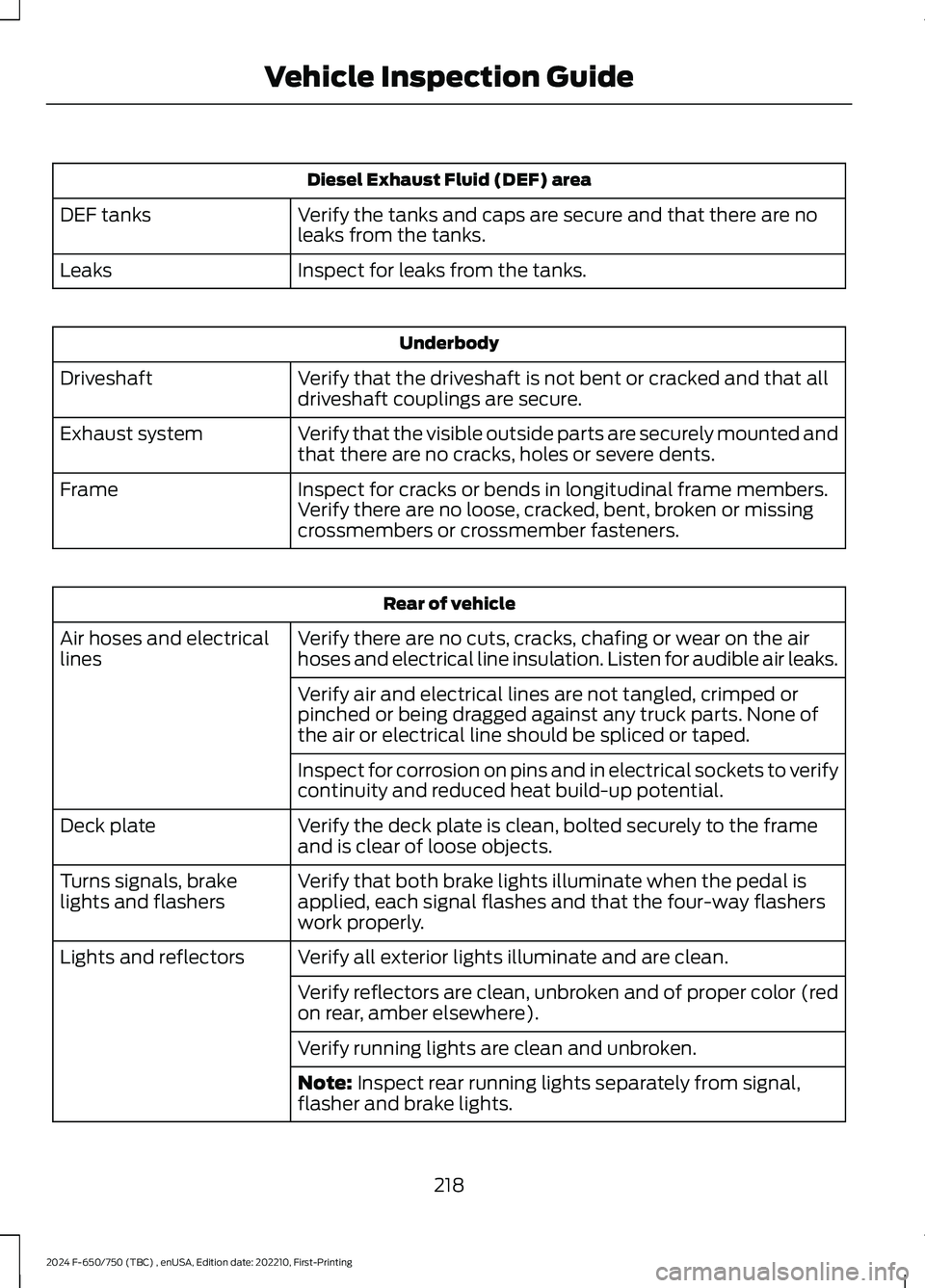
Diesel Exhaust Fluid (DEF) area
Verify the tanks and caps are secure and that there are noleaks from the tanks.DEF tanks
Inspect for leaks from the tanks.Leaks
Underbody
Verify that the driveshaft is not bent or cracked and that alldriveshaft couplings are secure.Driveshaft
Verify that the visible outside parts are securely mounted andthat there are no cracks, holes or severe dents.Exhaust system
Inspect for cracks or bends in longitudinal frame members.Verify there are no loose, cracked, bent, broken or missingcrossmembers or crossmember fasteners.
Frame
Rear of vehicle
Verify there are no cuts, cracks, chafing or wear on the airhoses and electrical line insulation. Listen for audible air leaks.Air hoses and electricallines
Verify air and electrical lines are not tangled, crimped orpinched or being dragged against any truck parts. None ofthe air or electrical line should be spliced or taped.
Inspect for corrosion on pins and in electrical sockets to verifycontinuity and reduced heat build-up potential.
Verify the deck plate is clean, bolted securely to the frameand is clear of loose objects.Deck plate
Verify that both brake lights illuminate when the pedal isapplied, each signal flashes and that the four-way flasherswork properly.
Turns signals, brakelights and flashers
Verify all exterior lights illuminate and are clean.Lights and reflectors
Verify reflectors are clean, unbroken and of proper color (redon rear, amber elsewhere).
Verify running lights are clean and unbroken.
Note: Inspect rear running lights separately from signal,flasher and brake lights.
218
2024 F-650/750 (TBC) , enUSA, Edition date: 202210, First-PrintingVehicle Inspection Guide
Page 224 of 386
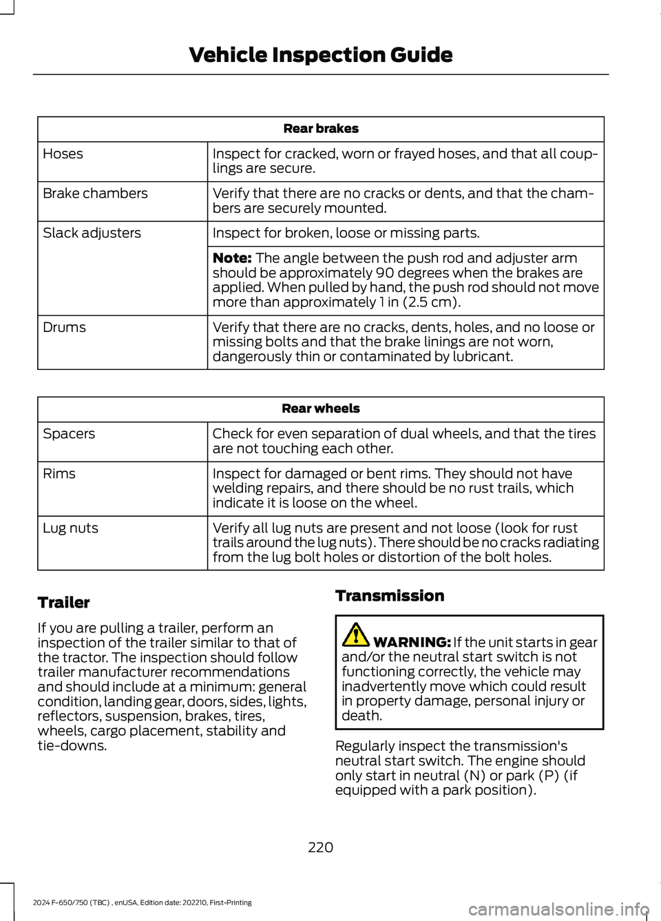
Rear brakes
Inspect for cracked, worn or frayed hoses, and that all coup-lings are secure.Hoses
Verify that there are no cracks or dents, and that the cham-bers are securely mounted.Brake chambers
Inspect for broken, loose or missing parts.Slack adjusters
Note: The angle between the push rod and adjuster armshould be approximately 90 degrees when the brakes areapplied. When pulled by hand, the push rod should not movemore than approximately 1 in (2.5 cm).
Verify that there are no cracks, dents, holes, and no loose ormissing bolts and that the brake linings are not worn,dangerously thin or contaminated by lubricant.
Drums
Rear wheels
Check for even separation of dual wheels, and that the tiresare not touching each other.Spacers
Inspect for damaged or bent rims. They should not havewelding repairs, and there should be no rust trails, whichindicate it is loose on the wheel.
Rims
Verify all lug nuts are present and not loose (look for rusttrails around the lug nuts). There should be no cracks radiatingfrom the lug bolt holes or distortion of the bolt holes.
Lug nuts
Trailer
If you are pulling a trailer, perform aninspection of the trailer similar to that ofthe tractor. The inspection should followtrailer manufacturer recommendationsand should include at a minimum: generalcondition, landing gear, doors, sides, lights,reflectors, suspension, brakes, tires,wheels, cargo placement, stability andtie-downs.
Transmission
WARNING: If the unit starts in gearand/or the neutral start switch is notfunctioning correctly, the vehicle mayinadvertently move which could resultin property damage, personal injury ordeath.
Regularly inspect the transmission'sneutral start switch. The engine shouldonly start in neutral (N) or park (P) (ifequipped with a park position).
220
2024 F-650/750 (TBC) , enUSA, Edition date: 202210, First-PrintingVehicle Inspection Guide
Page 255 of 386

Headlamp bulbs must be marked with anauthorized D.O.T. marking for NorthAmerica to make sure they have the properlamp performance, light brightness, lightpattern and safe visibility.
Install in the reverse order unless otherwisestated.
Headlamp Bulbs
1.Switch all of the lamps and the ignitionoff.
2.Remove the headlamp. SeeRemoving a Headlamp (page 250).
3.Release the clip and remove the bulb.
Note:Do not touch the bulb glass.
Note:If the bulb is accidentally touched, itshould be cleaned with rubbing alcoholbefore being used.
Front Clearance and IdentificationLamp (If Equipped)
1.Switch all of the lamps and the ignitionoff.
2.Remove the screw and lens from thelamp assembly.
3.Press the bulb in and turn the bulbcounterclockwise to remove it.
Brake Lamp, Rear Lamp, RearDirection Indicator, License PlateLamp and Reverse Lamp
1.Switch all of the lamps and the ignitionoff.
2.Remove the four screws and the lamplens from lamp assembly.
3.Remove the bulb by pulling it straightout.
CHANGING THE ENGINE-
MOUNTED AND DIESEL FUEL
CONDITIONER MODULE FUEL
FILTERS - 6.7L DIESEL
WARNING: Do not dispose of fuelin the household refuse or the publicsewage system. Use an authorized wastedisposal facility.
Your vehicle has two fuel filters. The firstfilter mounts on top of the engine on theleft-hand side. The second filter is insidethe diesel fuel conditioner module. Themodule is mounted between the inboardside of the fuel tank and the frame rail.
251
2024 F-650/750 (TBC) , enUSA, Edition date: 202210, First-PrintingMaintenanceE163825 E163828
Page 258 of 386

Removal
1.Disconnect the fuel lines by squeezingthe connector tabs and pulling the linesstraight off.
2.Rotate the filter fully counterclockwiseuntil the peg is at the far end of the slot.
3.Pull the filter straight up from thebracket and discard the filter.
Installation
1.Install the new filter into the filterbracket. Turn the filter clockwise tolock it in place.
2.Reconnect the fuel lines.
3.Switch the ignition on for 30 secondsand then switch the ignition off.Repeat this operation six times in a rowto purge any trapped air from the fuelsystem.
ELECTRICAL SYSTEM
INSPECTION
Periodically inspect electrical connectorson the outside of the cab and on the engineand frame for corrosion and tightness.Exposed terminals, such as the fuel sender,cranking motor, alternator andfeed-through studs, should be cleaned andre-coated with a lubricant sealing greasesuch as Motorcraft Silicone Brake CaliperGrease and Dielectric Compound XG-3, orequivalent. This should include the groundcable connector for batteries, engine andcab as well as the jump-starting stud.
Accessory Feed Connections
Vehicle electrical systems are complex andoften include powertrain components,such as engine and transmission controls,instrument panels and ABS. While mostsystems operate on battery voltage (12volts), some systems can be as high as 90volts or as low as five volts. See theElectrical Circuit Diagram Manuals,available from your vehicle’s manufacturer,to make sure that any extra body lights andaccessory connections to circuits are bothappropriate and not overloaded. Do notmake modifications to any vehicle controlsystem without first contacting anauthorized dealer.
254
2024 F-650/750 (TBC) , enUSA, Edition date: 202210, First-PrintingMaintenanceE2262151 E22621423
Page 271 of 386
3.Remove tar and grease with a bug andtar remover. We recommend that youuse Ford approved bug and tar removerif available.
4.Thoroughly rinse the wheels with waterafter cleaning.
If you intend on parking your vehicle for anextended period after cleaning the wheelswith a wheel cleaner, drive your vehicle fora few minutes before doing so. Thisreduces the risk of corrosion of the brakediscs, brake pads and linings.
Do not clean the wheels when they are hot.
Note: Some car washes could damagewheel rims and covers.
Note: Using non-recommended cleaners,harsh cleaning products, chrome wheelcleaners or abrasive materials coulddamage wheel rims, covers and bolts.
VEHICLE STORAGE
If you plan on storing your vehicle for 30days or more, read the followingmaintenance recommendations to makesure your vehicle stays in good operatingcondition.
We engineer and test all motor vehiclesand their components for reliable, regulardriving. Under various conditions,long-term storage may lead to degradedengine performance or failure unless youuse specific precautions to preserve enginecomponents.
General
•Store all vehicles in a dry, ventilatedplace.
•Protect from sunlight, if possible.
•If vehicles are stored outside, theyrequire regular maintenance to protectagainst rust and damage.
Body
•Wash your vehicle thoroughly toremove dirt, grease, oil, tar or mud fromexterior surfaces, rear-wheel housingand the underside of front fenders.
•Periodically wash your vehicle if it isstored in exposed locations.
•Touch-up exposed or primed metal toprevent rust.
•Cover chrome and stainless steel partswith a thick coat of auto wax to preventdiscoloration. Re-wax as necessarywhen you wash your vehicle.
•Lubricate all hood, door and luggagecompartment hinges and latches witha light grade oil.
•Cover interior trim to prevent fading.
•Keep all rubber parts free from oil andsolvents.
Engine
•Change the engine oil and filter prior tostorage because used engine oilcontains contaminates which maycause engine damage.
•Start the engine every 15 days for aminimum of 15 minutes. Run at fastidle with the climate controls set todefrost until the engine reaches normaloperating temperature.
•With your foot on the brake, shiftthrough all the gears while the engineis running.
•We recommend that you change theengine oil before you use your vehicleagain.
Fuel system
•Fill the fuel tank with high-quality fueluntil the first automatic shutoff of thefuel pump nozzle.
267
2024 F-650/750 (TBC) , enUSA, Edition date: 202210, First-PrintingVehicle Care
Page 300 of 386

BULB SPECIFICATION CHART
Replacement bulbs are specified in thechart below. Headlamp bulbs must bemarked with an authorized “D.O.T.” for
North America and an “E” for Europe toensure lamp performance, light brightnessand pattern and safe visibility. The correctbulbs will not damage the lamp assemblyor void the lamp assembly warranty andwill provide quality bulb illumination time.
Trade nameNumber of BulbsFunction
H13/90082Headlamps
W5W2Side marker lamp - front
3157NA2Park/Turn lamp- front
31572Tail/stop/turn/side marker
31572Reverse
31571License plate lamp
9121High-mount brake lamp
12V6W2Map lamp
5783Dome/reading lamps
28252Interior visor lamp
28252Mirror turn signal
28252Mirror clearance lamp
1945Front clearance lamps andfront identification lamps
Note:To replace instrument panel lights,see an authorized dealer.
ENGINE OIL CAPACITY AND
SPECIFICATION - 6.7L DIESEL
Use oil that meets the definedspecification and viscosity grade.
If you do not use oil that meets the definedspecification and viscosity grade, it couldresult in:
•Component damage that your vehiclewarranty does not cover.
•Longer engine cranking periods.
•Increased emission levels.
•Reduced vehicle performance.
•Reduced fuel economy.
296
2024 F-650/750 (TBC) , enUSA, Edition date: 202210, First-PrintingCapacities and Specifications