2024 CHEVROLET SILVERADO EV spare wheel
[x] Cancel search: spare wheelPage 187 of 429
Chevrolet Silverado EV Owner Manual (GMNA-Localizing-U.S./Canada-
16702912) - 2024 - CRC - 1/17/23
186 Driving and Operating
.Underbody Camera System: Provides a
view of the area underneath the vehicle
to avoid obstacles during off-roading
events. SeeSurround Vision System 0247.
Before Driving Your Vehicle Off-Road
Read all the information about
four-wheel-drive vehicles in this manual.
Know the local laws that apply to off-road
driving.
Have all necessary maintenance and service
work completed.
Charge the vehicle and check inflation
pressure in all tires, including the spare,
if equipped.
Loading the Vehicle for Off-Road Driving
Caution
Placing tall or oversized items near or
against the spoiler or the lamp above the
truck bed can result in vehicle damage.
To prevent vehicle damage, properly store
cargo in the truck bed away from the
spoiler and the lamp using the cargo
tie-downs.
{Warning
.Unsecured cargo on the load floor can
be tossed about when driving over
rough terrain. You or your passengers
can be struck by flying objects. Secure
the cargo properly.
.Keep cargo in the cargo area as far
forward and as low as possible. The
heaviest things should be on the floor,
forward of the rear axle.
.Heavy loads on the roof raise the
vehicle's center of gravity, making it
more likely to roll over. You can be
seriously or fatally injured if the
vehicle rolls over. Put heavy loads
inside the cargo area, not on the roof.
For more information about loading the
vehicle, see Vehicle Load Limits 0193 and
Tires 0344.
Environmental Concerns
Always use established trails, roads, and
areas that are reserved for public off-road
recreational driving. Obey all posted
regulations.
Do not damage shrubs, flowers, trees,
grasses, or disturb wildlife.
Driving on Hills
Driving safely on hills requires good
judgment and an understanding of what the
vehicle can and cannot do.
{Warning
Many hills are simply too steep for any
vehicle. Driving down hills can cause loss
of control. Driving across hills can cause a
rollover. You could be injured or killed.
Do not drive on steep hills.
Before driving on a hill, assess the
steepness, traction, and obstructions. If the
terrain ahead cannot be seen, get out of the
vehicle and walk the hill before driving
further.
When driving on hills:
.Use L (Low) mode and keep a firm grip on
the steering wheel.
.Maintain a slow speed.
{Warning
Driving to the top of a hill at high speed
can cause a crash. There could be a
drop-off, embankment, cliff, or even (Continued)
Page 254 of 429
Chevrolet Silverado EV Owner Manual (GMNA-Localizing-U.S./Canada-
16702912) - 2024 - CRC - 1/17/23
Driving and Operating 253
The Transparent Trailer image is not the
right size:
.The size of the image overlaid on the face
of the trailer may be too large or too
small if the measurements input in the
Trailering App are not accurate. See
Trailering App0310 for details on how to
take measurements.
The preview may not be provided or the
wrong preview may be provided if:
.The accessory cameras are not recognized.
Ensure that the accessory camera(s) are
connected and restart the vehicle.
.The accessory trailer cameras are
swapped at the hitch connector. Ensure
that the accessory camera(s) are
connected to the correct input.
.The accessory trailer camera(s) are not
installed according to the installation
instructions.
A feature may be unavailable or not
activating as expected if:
.The trailer is not compatible.
.The customization is disabled. Check the
customization settings where applicable.
.The accessory trailer cameras are
swapped at the hitch connector. Ensure
that the accessory camera(s) are
connected to the correct camera input.
.A trailer profile is not configured and
selected.
.The entered trailer profile dimensions are
inaccurate. Measurements are expected to
be made to the nearest centimeter or
inch. Enter accurate measurements and
reattempt calibration.
.The trailer position is not known. Drive
straight forward to learn trailer position.
.The rear vehicle camera is obstructed by
dirt or debris. Check cameras and clean as
needed.
.The accessory trailer cameras were
plugged in when the vehicle was running.
Prior to plugging in the trailer camera,
the vehicle needs to be off with all doors
closed for at least five minutes.
An unexpected view may display when:
.During the initial portions of the drive,
Transparent Trailer Degraded may be
displayed until truck or trailer articulation
angle can be calculated. Once calculated,
the expected transparent trailer view will
be displayed. Certain viewing features may experience
degraded performance if:
.The entered trailer profile dimensions are
inaccurate. Measurements are expected to
be made to the nearest centimeter or
inch. Enter accurate measurements and
reattempt calibration.
.The rear vehicle camera is obstructed by
dirt or debris. Check cameras and clean as
needed.
For trailers with outboard wheels:
.Performance for Transparent Trailer and
Jack Knife Detection are optimized when
the entered value for trailer width reflects
the width of the box of the trailer. If total
width is entered:
.The inlayed camera view in
Transparent Trailer View may appear
wider than the trailer face.
.The rear vehicle camera is obstructed by
dirt or debris. Check cameras and clean as
needed.
.Jack Knife Detection alerts may activate
prematurely.
Page 255 of 429
Chevrolet Silverado EV Owner Manual (GMNA-Localizing-U.S./Canada-
16702912) - 2024 - CRC - 1/17/23
254 Driving and Operating
.Performance for Transparent Trailer and
Jack Knife Detection are optimized when
the entered value for trailer width reflects
the width of the box of the trailer. If total
width is entered:
.The inlayed camera view in
Transparent Trailer View may appear
wider than the trailer face.
.Jack Knife Detection alerts may
activate prematurely.
.Performance for Rear Trailer Guidance
Lines and Trailer Length Indicator Overlays
are optimized when the entered value for
trailer width reflects the total width of
the trailer including outboard wheels.
If the trailer box width is entered:
.The Rear Trailer Guidance Lines will
appear narrower than the actual path
of the trailer.
.The Trailer Length Indicator Overlays
will appear closer and possibly overlap
with the trailer.
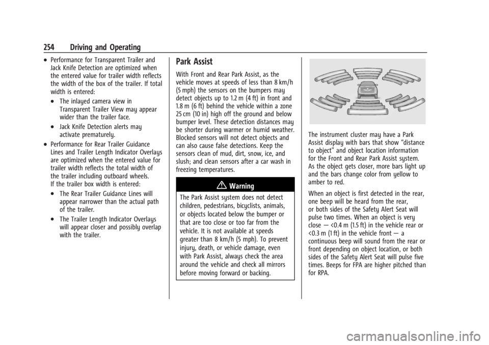
Park Assist
With Front and Rear Park Assist, as the
vehicle moves at speeds of less than 8 km/h
(5 mph) the sensors on the bumpers may
detect objects up to 1.2 m (4 ft) in front and
1.8 m (6 ft) behind the vehicle within a zone
25 cm (10 in) high off the ground and below
bumper level. These detection distances may
be shorter during warmer or humid weather.
Blocked sensors will not detect objects and
can also cause false detections. Keep the
sensors clean of mud, dirt, snow, ice, and
slush; and clean sensors after a car wash in
freezing temperatures.
{Warning
The Park Assist system does not detect
children, pedestrians, bicyclists, animals,
or objects located below the bumper or
that are too close or too far from the
vehicle. It is not available at speeds
greater than 8 km/h (5 mph). To prevent
injury, death, or vehicle damage, even
with Park Assist, always check the area
around the vehicle and check all mirrors
before moving forward or backing.
The instrument cluster may have a Park
Assist display with bars that show“distance
to object” and object location information
for the Front and Rear Park Assist system.
As the object gets closer, more bars light up
and the bars change color from yellow to
amber to red.
When an object is first detected in the rear,
one beep will be heard from the rear,
or both sides of the Safety Alert Seat will
pulse two times. When an object is very
close —<0.4 m (1.5 ft) in the vehicle rear or
<0.3 m (1 ft) in the vehicle front —a
continuous beep will sound from the rear or
front depending on object location, or both
sides of the Safety Alert Seat will pulse five
times. Beeps for FPA are higher pitched than
for RPA.
Page 314 of 429
Chevrolet Silverado EV Owner Manual (GMNA-Localizing-U.S./Canada-
16702912) - 2024 - CRC - 1/17/23
Driving and Operating 313
a maximum of two minutes to detect and
label each TTPMS sensor. After each sensor
is learned, a check mark appears next to the
tire, the vehicle horn sounds, the vehicle
brake lamps flash, and all working trailer
lamps flash.
The recommended tire pressure must be
entered for the trailer tires. An alert appears
when a trailer tire's pressure is high or low.
Tool Method: A TTPMS activation tool can
be purchased separately to learn the trailer
TTPMS sensor locations.
Manual Method: Without the TTPMS
activation tool, the air pressure can be
increased or decreased in each tire for
10 seconds. Do not exceed the maximum
inflation pressure found on the tire
sidewalls. Make sure to readjust tire
pressure to the recommended level when
the process is complete.
Sensor Learning Steps
To complete the sensor-to-vehicle learn
process:1. Touch Start on the Learn Sensors screen. The horn chirps twice and the Learning
Active screen appears on the
infotainment display. 2. Start with the driver side front
trailer tire.
3. Activate the tool near the valve stem or adjust the air pressure of this tire until
the horn chirps and all working vehicle
and trailer lights flash.
The process stops without saving the
sensor locations if this step takes more
than two minutes.
4. Move to the next tire and repeat Step 3 for each sensor. The horn chirps twice
when all sensors are completed.
5. Return to the vehicle to complete the setup.
Maintenance Reminders
To set up maintenance reminders, touch the
Trailer Maintenance icon. Follow the
on-screen prompts. The maximum number
of reminders is 50.
Camera Views and Guides
To set up the trailer camera and guideline
features, if equipped, touch the Camera
Views and Guides icon.
1. Select the number of axles on the trailer.
2. Select the wheel location on the trailer (inboard or outboard). 3. Enter the trailer dimensions as prompted.
Follow the on-screen instructions to
complete setup for available features.
Certain trailer features require a compatible
trailer profile be configured and selected.
A compatible trailer is a box-type trailer
(cargo, camper, etc.) with a conventional
hitch.
Transparent Trailer Setup
If equipped, the rear trailer camera must be
mounted on the trailer and electrically
connected to the vehicle before transparent
trailer feature can be used. See Assistance
Systems for Parking or Backing 0246.
Follow the on-screen instructions to enter
the trailer dimensions.
Trailer dimensions must be in range and
transparent trailer must be calibrated
before use.
.Trailer Length: Measure from center of
coupler to furthest rear point on the
trailer.
.Trailer Total Width: Measure from the left
most edge of trailer, including the wheels,
to the right most edge.
Page 324 of 429
Chevrolet Silverado EV Owner Manual (GMNA-Localizing-U.S./Canada-
16702912) - 2024 - CRC - 1/13/23
Vehicle Care 323
Vehicle Care
General Information
General Information . . . . . . . . . . . . . . . . . . . 324
California Perchlorate MaterialsRequirements . . . . . . . . . . . . . . . . . . . . . . . . 324
Accessories and Modifications . . . . . . . . . 324
Vehicle Checks
Doing Your Own Service Work . . . . . . . . 324
Underhood Compartment Overview . . . 325
Cooling System . . . . . . . . . . . . . . . . . . . . . . . . 327
Washer Fluid . . . . . . . . . . . . . . . . . . . . . . . . . . 328
Brakes . . . . . . . . . . . . . . . . . . . . . . . . . . . . . . . . . 328
Brake Fluid . . . . . . . . . . . . . . . . . . . . . . . . . . . . 329
Battery - North America . . . . . . . . . . . . . . . 330
Noise Control System (RST Only) . . . . . . 332
Wiper Blade Replacement . . . . . . . . . . . . . 333
Glass Replacement . . . . . . . . . . . . . . . . . . . . . 333
Windshield Replacement . . . . . . . . . . . . . . 334
Gas Strut(s) . . . . . . . . . . . . . . . . . . . . . . . . . . . 334
Headlamp Aiming
Front Headlamp Aiming . . . . . . . . . . . . . . . 335
Bulb Replacement
LED Lighting . . . . . . . . . . . . . . . . . . . . . . . . . . . 335
Electrical System
High Voltage Devices and Wiring . . . . . . 335
Electrical System Overload . . . . . . . . . . . . . 335 Fuses and Circuit Breakers . . . . . . . . . . . . . 337
Underhood Compartment Fuse
Block . . . . . . . . . . . . . . . . . . . . . . . . . . . . . . . . 337
Instrument Panel Fuse Block (Left) . . . . 340
Instrument Panel Fuse Block (Right) . . . 342
Wheels and Tires
Tires . . . . . . . . . . . . . . . . . . . . . . . . . . . . . . . . . . 344
All-Season Tires . . . . . . . . . . . . . . . . . . . . . . . . 345
Winter Tires . . . . . . . . . . . . . . . . . . . . . . . . . . . 345
Tire Sidewall Labeling . . . . . . . . . . . . . . . . . 346
Tire Designations . . . . . . . . . . . . . . . . . . . . . . 347
Tire Terminology and Definitions . . . . . . 347
Tire Pressure . . . . . . . . . . . . . . . . . . . . . . . . . . 349
Tire Pressure for High-Speed Operation . . . . . . . . . . . . . . . . . . . . . . . . . . . 350
Tire Pressure Monitor System . . . . . . . . . . 351
Tire Pressure Monitor Operation . . . . . . . 351
Tire Inspection . . . . . . . . . . . . . . . . . . . . . . . . . 355
Tire Rotation . . . . . . . . . . . . . . . . . . . . . . . . . . 356
When It Is Time for New Tires . . . . . . . . 357
Buying New Tires . . . . . . . . . . . . . . . . . . . . . 358
Different Size Tires and Wheels . . . . . . . 359
Uniform Tire Quality Grading . . . . . . . . . 359
Wheel Alignment and Tire Balance . . . . 360
Wheel Replacement . . . . . . . . . . . . . . . . . . . 360
Tire Chains . . . . . . . . . . . . . . . . . . . . . . . . . . . . 361
If a Tire Goes Flat . . . . . . . . . . . . . . . . . . . . . 362
Tire Sealant and Compressor Kit . . . . . . . 363
Storing the Tire Sealant and
Compressor Kit . . . . . . . . . . . . . . . . . . . . . . 368 Tire Changing . . . . . . . . . . . . . . . . . . . . . . . . . 369
Full-Size Spare Tire . . . . . . . . . . . . . . . . . . . . 374
Jump Starting
Jump Starting - North America . . . . . . . . 375
Towing the Vehicle
Transporting a Disabled Vehicle . . . . . . . 378
Recreational Vehicle Towing . . . . . . . . . . . 379
Appearance Care
Exterior Care . . . . . . . . . . . . . . . . . . . . . . . . . . 379
Interior Care . . . . . . . . . . . . . . . . . . . . . . . . . . 384
Floor Mats . . . . . . . . . . . . . . . . . . . . . . . . . . . . 387
Page 341 of 429
Chevrolet Silverado EV Owner Manual (GMNA-Localizing-U.S./Canada-
16702912) - 2024 - CRC - 1/13/23
340 Vehicle Care
FusesUsage
F66 –
F67 EMB/GRILL LIGHT
F68 HDLP_LT
F69 MIDGATE LEFT MOTOR F70 EBCM 1 F71 DC/AC INV
F72 Spare
F73 –
F74 –
F75 Spare
F76 HDLP_RT F77 –
F78 MIDGATE CROSS BAR MOTOR 2
MIDGATE CROSS BAR
MOTOR 1
F79 PCV_PEEV_ALD FR RADAR/VIRTUAL KEY
F80 IECR 2 F81 IECL 1 Fuses
Usage
F82 –
F83 –
F84 V2LIM F85 Spare HVS (HIGH VOLTAGE
SERVICE DISCONNECT)
F86 HORN F87 FRT WSHR PMP
F88 –
F89 –
F90 –
F91 –Instrument Panel Fuse Block (Left)
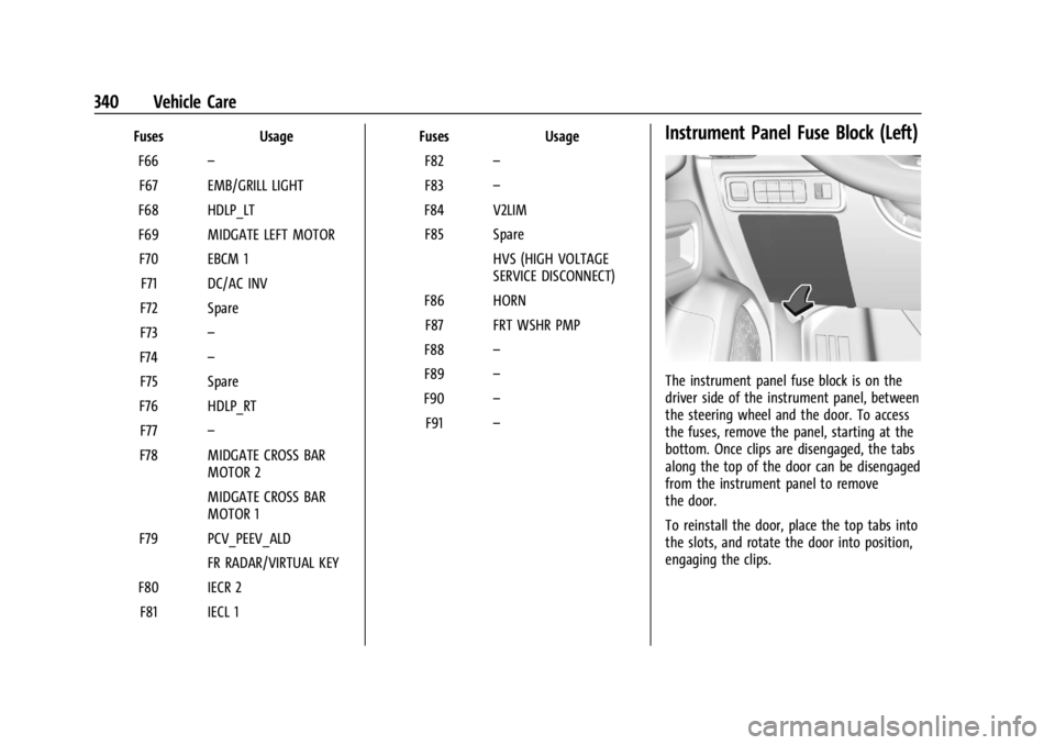
The instrument panel fuse block is on the
driver side of the instrument panel, between
the steering wheel and the door. To access
the fuses, remove the panel, starting at the
bottom. Once clips are disengaged, the tabs
along the top of the door can be disengaged
from the instrument panel to remove
the door.
To reinstall the door, place the top tabs into
the slots, and rotate the door into position,
engaging the clips.
Page 345 of 429
Chevrolet Silverado EV Owner Manual (GMNA-Localizing-U.S./Canada-
16702912) - 2024 - CRC - 1/13/23
344 Vehicle Care
FusesUsage
F10 Displays SPARE
F11 CGM –Central Gateway
Module
SPARE
F12 SPARE
F13 SPARE DLC–Data Link Connection
F14 BODY MISC BODY MISC 1
F15 MISC_IP 1
F16 SPARE F17 SPARE
F18 BDY 1 HDLNR
F19 VICM TPIM IGN –Vehicle
Integration Control
Module/Traction Power
Inverter Module/Ignition
F20 OHC HUD Fuses
Usage
F21 VCU VCU 2
F22 SPARE
F23 SPARE
F24 FCM_RLH_UGDO F25 USB_ROW 2
F26 SPARE F27 USB
F28 SPARE
F29 FRT_HVAC_DIS
F30 SPARE F31 BCM 3 –Body Control
Module 3
F32 HSWM –Heating Steering
Wheel Module
F33 SPARE
F34 SPARE F35 SPARE
F36 SPARE F37 SPARE Fuses
Usage
F38 SPARE
F39 SPARE
F40 SPARE
Circuit
Breakers Usage
CB01 APO –Auxiliary Power
Outlet Center Console
CB02 SPARE
Wheels and Tires
Tires
Every new GM vehicle has high-quality
tires made by a leading tire
manufacturer. See the warranty manual
for information regarding the tire
warranty and where to get service. For
additional information refer to the tire
manufacturer.
Page 352 of 429
Chevrolet Silverado EV Owner Manual (GMNA-Localizing-U.S./Canada-
16702912) - 2024 - CRC - 1/13/23
Vehicle Care 351
Warning (Continued)
are in excellent condition, and are set to
the correct cold tire inflation pressure for
the vehicle load.
Tire Pressure Monitor System
The Tire Pressure Monitor System (TPMS)
uses radio and sensor technology to check
tire pressure levels. The TPMS sensors
monitor the air pressure in your tires and
transmit tire pressure readings to a receiver
located in the vehicle.
Each tire, including the spare (if provided),
should be checked monthly when cold and
inflated to the inflation pressure
recommended by the vehicle manufacturer
on the vehicle placard or tire inflation
pressure label. (If your vehicle has tires of a
different size than the size indicated on the
vehicle placard or tire inflation pressure
label, you should determine the proper tire
inflation pressure for those tires.)
As an added safety feature, your vehicle has
been equipped with a tire pressure
monitoring system (TPMS) that illuminates a
low tire pressure telltale when one or more
of your tires is significantly under-inflated.Accordingly, when the low tire pressure
telltale illuminates, you should stop and
check your tires as soon as possible, and
inflate them to the proper pressure. Driving
on a significantly under-inflated tire causes
the tire to overheat and can lead to tire
failure. Under-inflation also reduces energy
efficiency and tire tread life, and may affect
the vehicle's handling and stopping ability.
Please note that the TPMS is not a
substitute for proper tire maintenance, and
it is the driver's responsibility to maintain
correct tire pressure, even if under-inflation
has not reached the level to trigger
illumination of the TPMS low tire pressure
telltale.
Your vehicle has also been equipped with a
TPMS malfunction indicator to indicate when
the system is not operating properly. The
TPMS malfunction indicator is combined
with the low tire pressure telltale. When the
system detects a malfunction, the telltale
will flash for approximately one minute and
then remain continuously illuminated. This
sequence will continue upon subsequent
vehicle start-ups as long as the malfunction
exists.
When the malfunction indicator is
illuminated, the system may not be able to
detect or signal low tire pressure as
intended. TPMS malfunctions may occur for
a variety of reasons, including the
installation of replacement or alternate tires
or wheels on the vehicle that prevent the
TPMS from functioning properly. Always
check the TPMS malfunction telltale after
replacing one or more tires or wheels on
your vehicle to ensure that the replacement
or alternate tires and wheels allow the
TPMS to continue to function properly.
See
Tire Pressure Monitor Operation 0351.
See Radio Frequency Statement 0404.
Tire Pressure Monitor Operation
This vehicle may have a Tire Pressure
Monitor System (TPMS). The TPMS is
designed to warn the driver when a low tire
pressure condition exists. TPMS sensors are
mounted onto each tire and wheel
assembly, excluding the spare tire and
wheel assembly. The TPMS sensors monitor
the air pressure in the tires and transmit the
tire pressure readings to a receiver located
in the vehicle.