2024 CHEVROLET CORVETTE transmission
[x] Cancel search: transmissionPage 6 of 362

Chevrolet Corvette Owner Manual (GMNA-Localizing-U.S./Canada/Mexico-
17272984) - 2024 - CRC - 2/20/23
Introduction 5
1.Air Vents 0153.
2. Turn Signal Lever. See Turn and
Lane-Change Signals 0112.
Exterior Lamp Controls 0109.
3. Manual Shift Paddles. See Manual Mode
0 187.
4. Instrument Cluster 081.
5. Windshield Wiper/Washer 075.
6. Volume Control Knob and Infotainment Home Button. See Overview0117.
7. Infotainment Display. See Using the
System 0120.
8. Alarm System Indicator Light. See Vehicle
Alarm System 022.
Light Sensor. See Automatic Headlamp
System 0111.
9. Dual Automatic Climate Control System
0150.
Driver and Passenger Heated and
Ventilated Seat Controls (If Equipped).
See Heated and Ventilated Front Seats
0 44. 10.
Traction Control/Electronic Stability
Control 0194.
Curb View Camera (If Equipped). See
Assistance Systems for Parking or Backing
0 215.
Front Lift System Control (If Equipped).
See Front Lift System 0205.
11. Driver Mode Control 0196.
12. Shift Switches. See Dual Clutch
Transmission 0184.
13. Hybrid Battery Charging (Charge+). See Driver Mode Control 0196.
Auto Stop Disable Switch. See Stop/Start
System 0180.
14. Keyless Ignition. See Ignition Positions
0 178.
15. Driver Information Center (DIC) Controls. SeeDriver Information Center (DIC) 099.
16. Heated Steering Wheel 075 (If
Equipped).
17. Bluetooth Controls. See Steering Wheel
Controls 0119.
Voice Recognition Controls. See Steering
Wheel Controls 0119. 18. Volume Control Buttons. See
Steering
Wheel Controls 0119.
19. Horn 075.
20. Favorites Select Buttons. Steering Wheel
Controls 0119.
21. Z-Mode Control. See Driver Mode Control
0 196.
Forward Collision Alert (FCA) System
0 218.
22. Cruise Control 0212.
23. Electric Parking Brake 0192.
24. Data Link Connector (DLC) (Out of View). SeeMalfunction Indicator Lamp (Check
Engine Light) 090.
25. Instrument Panel Illumination Control
0113.
26. Head-Up Display Controls (If Equipped). SeeHead-Up Display (HUD) 0102.
Page 17 of 362
Chevrolet Corvette Owner Manual (GMNA-Localizing-U.S./Canada/Mexico-
17272984) - 2024 - CRC - 2/20/23
16 Keys, Doors, and Windows
From Outside the Vehicle
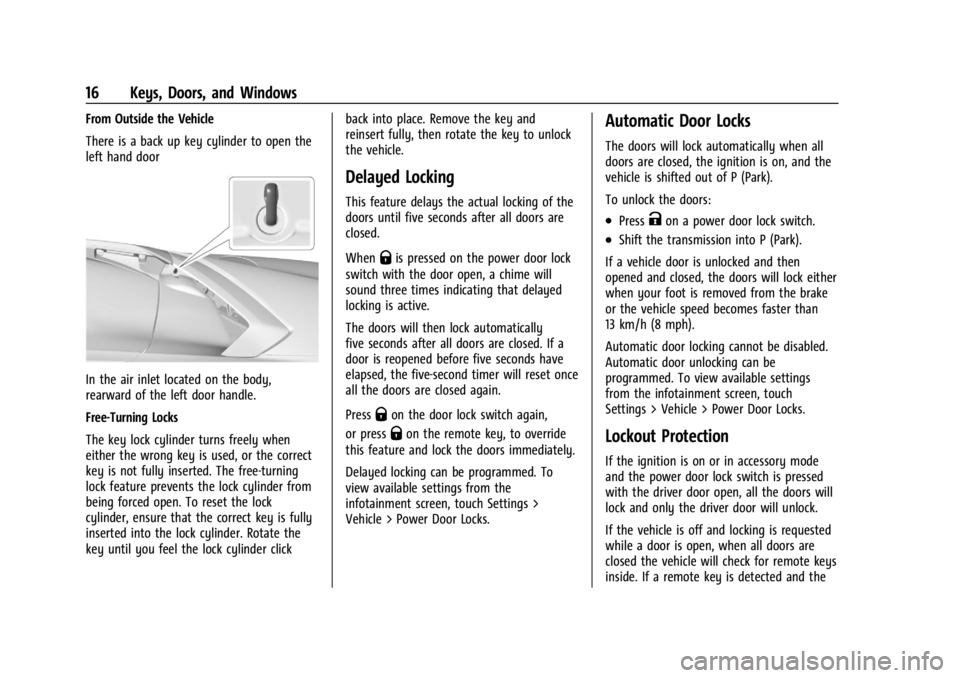
There is a back up key cylinder to open the
left hand door
In the air inlet located on the body,
rearward of the left door handle.
Free-Turning Locks
The key lock cylinder turns freely when
either the wrong key is used, or the correct
key is not fully inserted. The free-turning
lock feature prevents the lock cylinder from
being forced open. To reset the lock
cylinder, ensure that the correct key is fully
inserted into the lock cylinder. Rotate the
key until you feel the lock cylinder clickback into place. Remove the key and
reinsert fully, then rotate the key to unlock
the vehicle.
Delayed Locking
This feature delays the actual locking of the
doors until five seconds after all doors are
closed.
When
Qis pressed on the power door lock
switch with the door open, a chime will
sound three times indicating that delayed
locking is active.
The doors will then lock automatically
five seconds after all doors are closed. If a
door is reopened before five seconds have
elapsed, the five-second timer will reset once
all the doors are closed again.
Press
Qon the door lock switch again,
or press
Qon the remote key, to override
this feature and lock the doors immediately.
Delayed locking can be programmed. To
view available settings from the
infotainment screen, touch Settings >
Vehicle > Power Door Locks.
Automatic Door Locks
The doors will lock automatically when all
doors are closed, the ignition is on, and the
vehicle is shifted out of P (Park).
To unlock the doors:
.PressKon a power door lock switch.
.Shift the transmission into P (Park).
If a vehicle door is unlocked and then
opened and closed, the doors will lock either
when your foot is removed from the brake
or the vehicle speed becomes faster than
13 km/h (8 mph).
Automatic door locking cannot be disabled.
Automatic door unlocking can be
programmed. To view available settings
from the infotainment screen, touch
Settings > Vehicle > Power Door Locks.
Lockout Protection
If the ignition is on or in accessory mode
and the power door lock switch is pressed
with the driver door open, all the doors will
lock and only the driver door will unlock.
If the vehicle is off and locking is requested
while a door is open, when all doors are
closed the vehicle will check for remote keys
inside. If a remote key is detected and the
Page 18 of 362
Chevrolet Corvette Owner Manual (GMNA-Localizing-U.S./Canada/Mexico-
17272984) - 2024 - CRC - 2/20/23
Keys, Doors, and Windows 17
number of remote keys inside has not
reduced, the driver door will unlock and the
horn will chirp three times.
Lockout Protection can be manually
overridden with the driver door open by
pressing and holding
Qon the power door
lock switch.
Doors
Hood
Hood Release
{Warning
Do not drive the vehicle if the hood is
not latched completely. The hood could
open fully, block your vision, and cause a
crash. You or others could be injured.
Always close the hood completely before
driving. When the hood is not closed, the
vehicle will not exceed 42 km/h
(26 mph). Close the hood to drive faster
than 42 km/h (26 mph).
{Warning
When closing the hood, keep hands out
of the opening between the body and
the trunk. The vehicle features a self
closing power latch. You or others could
be injured.
The hood compartment can be accessed in
several ways.
Ensure the hood is clear of any objects
before opening.
This vehicle prevents from shifting out of
P (Park) when the hood is not closed. Close
the hood to shift out of P (Park). Confirm
the hood is closed by checking that the
hood is flush with the surrounding
components.
If the hood is closed but the ajar message is
still present, then the transmission lockout
can be overridden by holding the brake for
20 seconds and then shifting into D (Drive).
In this case, the vehicle will not exceed
42 km/h (26 mph). See your dealer for
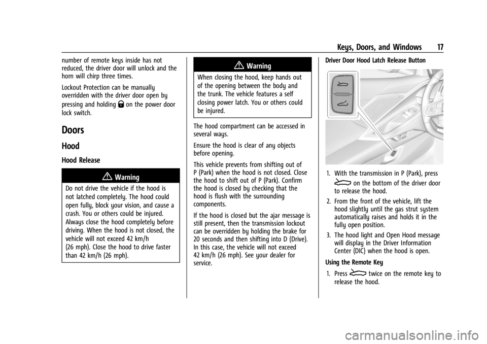
service. Driver Door Hood Latch Release Button
1. With the transmission in P (Park), press
Eon the bottom of the driver door
to release the hood.
2. From the front of the vehicle, lift the hood slightly until the gas strut system
automatically raises and holds it in the
fully open position.
3. The hood light and Open Hood message will display in the Driver Information
Center (DIC) when the hood is open.
Using the Remote Key
1. Press
Etwice on the remote key to
release the hood.
Page 32 of 362
Chevrolet Corvette Owner Manual (GMNA-Localizing-U.S./Canada/Mexico-
17272984) - 2024 - CRC - 2/20/23
Keys, Doors, and Windows 31
Sun Visors
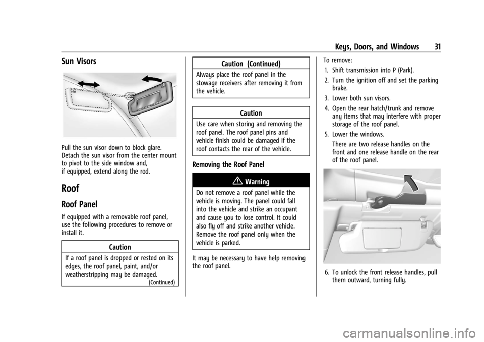
Pull the sun visor down to block glare.
Detach the sun visor from the center mount
to pivot to the side window and,
if equipped, extend along the rod.
Roof
Roof Panel
If equipped with a removable roof panel,
use the following procedures to remove or
install it.
Caution
If a roof panel is dropped or rested on its
edges, the roof panel, paint, and/or
weatherstripping may be damaged.
(Continued)
Caution (Continued)
Always place the roof panel in the
stowage receivers after removing it from
the vehicle.
Caution
Use care when storing and removing the
roof panel. The roof panel pins and
vehicle finish could be damaged if the
roof contacts the rear of the vehicle.
Removing the Roof Panel
{Warning
Do not remove a roof panel while the
vehicle is moving. The panel could fall
into the vehicle and strike an occupant
and cause you to lose control. It could
also fly off and strike another vehicle.
Remove the roof panel only when the
vehicle is parked.
It may be necessary to have help removing
the roof panel. To remove:
1. Shift transmission into P (Park).
2. Turn the ignition off and set the parking brake.
3. Lower both sun visors.
4. Open the rear hatch/trunk and remove any items that may interfere with proper
storage of the roof panel.
5. Lower the windows. There are two release handles on the
front and one release handle on the rear
of the roof panel.
6. To unlock the front release handles, pullthem outward, turning fully.
Page 34 of 362
Chevrolet Corvette Owner Manual (GMNA-Localizing-U.S./Canada/Mexico-
17272984) - 2024 - CRC - 2/20/23
Keys, Doors, and Windows 33
{Warning
Do not push from the sides of the roof
panel when seating the panel into the
upper receivers for storage. Pushing from
the sides may result in injury from
pinched fingers. Only push along the top
edge of the roof panel.
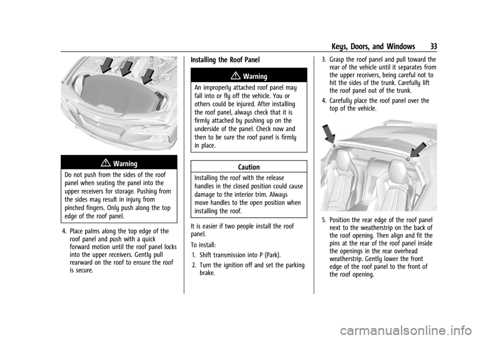
4. Place palms along the top edge of the roof panel and push with a quick
forward motion until the roof panel locks
into the upper receivers. Gently pull
rearward on the roof to ensure the roof
is secure.
Installing the Roof Panel
{Warning
An improperly attached roof panel may
fall into or fly off the vehicle. You or
others could be injured. After installing
the roof panel, always check that it is
firmly attached by pushing up on the
underside of the panel. Check now and
then to be sure the roof panel is firmly
in place.
Caution
Installing the roof with the release
handles in the closed position could cause
damage to the interior trim. Always
move handles to the open position when
installing the roof.
It is easier if two people install the roof
panel.
To install: 1. Shift transmission into P (Park).
2. Turn the ignition off and set the parking brake. 3. Grasp the roof panel and pull toward the
rear of the vehicle until it separates from
the upper receivers, being careful not to
hit the sides of the trunk. Carefully lift
the roof panel out of the trunk.
4. Carefully place the roof panel over the top of the vehicle.
5. Position the rear edge of the roof panelnext to the weatherstrip on the back of
the roof opening. Then align and fit the
pins at the rear of the roof panel inside
the openings in the rear overhead
weatherstrip. Gently lower the front
edge of the roof panel to the front of
the roof opening.
Page 75 of 362

Chevrolet Corvette Owner Manual (GMNA-Localizing-U.S./Canada/Mexico-
17272984) - 2024 - CRC - 2/20/23
74 Instruments and Controls
Instruments and Controls
Controls
Steering Wheel Adjustment . . . . . . . . . . . . . 75
Heated Steering Wheel . . . . . . . . . . . . . . . . . 75
Horn . . . . . . . . . . . . . . . . . . . . . . . . . . . . . . . . . . . . 75
Windshield Wiper/Washer . . . . . . . . . . . . . . 75
Compass . . . . . . . . . . . . . . . . . . . . . . . . . . . . . . . 76
Clock . . . . . . . . . . . . . . . . . . . . . . . . . . . . . . . . . . . 76
Power Outlets . . . . . . . . . . . . . . . . . . . . . . . . . . 77
Wireless Charging . . . . . . . . . . . . . . . . . . . . . . 78
Warning Lights, Gauges, and Indicators
Warning Lights, Gauges, andIndicators . . . . . . . . . . . . . . . . . . . . . . . . . . . . 80
Instrument Cluster . . . . . . . . . . . . . . . . . . . . . . 81
Speedometer . . . . . . . . . . . . . . . . . . . . . . . . . . . 85
Odometer . . . . . . . . . . . . . . . . . . . . . . . . . . . . . . 85
Trip Odometer . . . . . . . . . . . . . . . . . . . . . . . . . . 85
Tachometer . . . . . . . . . . . . . . . . . . . . . . . . . . . . 85
Battery Gauge (High Voltage) . . . . . . . . . . 86
Stealth Drive Mode Capability Gauge . . . . . . . . . . . . . . . . . . . . . . . . . . . . . . . . 86
Fuel Gauge . . . . . . . . . . . . . . . . . . . . . . . . . . . . . 86
Hybrid Battery Charging Light (Charge+) . . . . . . . . . . . . . . . . . . . . . . . . . . . . . 87
Power Indicator Gauge . . . . . . . . . . . . . . . . . 87
Engine Coolant Temperature Gauge . . . . 87
Transmission Temperature Gauge . . . . . . 88
Seat Belt Reminders . . . . . . . . . . . . . . . . . . . . 88 Airbag Readiness Light . . . . . . . . . . . . . . . . . 88
Passenger Airbag Status Indicator . . . . . . 89
Charging System Light (12-Volt
Battery) . . . . . . . . . . . . . . . . . . . . . . . . . . . . . . 90
Malfunction Indicator Lamp (Check
Engine Light) . . . . . . . . . . . . . . . . . . . . . . . . . 90
Front Lift System Light . . . . . . . . . . . . . . . . . 91
Brake System Warning Light . . . . . . . . . . . 92
Electric Parking Brake Light . . . . . . . . . . . . . 92
Service Electric Parking Brake Light . . . . . 92
Antilock Brake System (ABS) Warning Light . . . . . . . . . . . . . . . . . . . . . . . . . . . . . . . . . . 93
Performance Transmission Active . . . . . . . 93
All-Wheel-Drive Light . . . . . . . . . . . . . . . . . . . 93
Lane Keep Assist (LKA) Light . . . . . . . . . . . 94
Automatic Emergency Braking (AEB) Disabled Light . . . . . . . . . . . . . . . . . . . . . . . . 94
Vehicle Ahead Indicator . . . . . . . . . . . . . . . . 94
Pedestrian Ahead Indicator . . . . . . . . . . . . . 94
Traction Off Light . . . . . . . . . . . . . . . . . . . . . . 95
Traction Control System (TCS)/Electronic Stability Control Light . . . . . . . . . . . . . . . . 95
Electronic Stability Control (ESC) Off Light . . . . . . . . . . . . . . . . . . . . . . . . . . . . . . . . . . 95
Engine Coolant Temperature Warning Light . . . . . . . . . . . . . . . . . . . . . . . . . . . . . . . . . 96
Driver Mode Control Light . . . . . . . . . . . . . . 96
Tire Pressure Light . . . . . . . . . . . . . . . . . . . . . . 97
Engine Oil Pressure Light . . . . . . . . . . . . . . . 97
Low Fuel Warning Light . . . . . . . . . . . . . . . . 97 Auto Stop Indicator . . . . . . . . . . . . . . . . . . . . 98
Traffic Sign Indicator . . . . . . . . . . . . . . . . . . . 98
Security Light . . . . . . . . . . . . . . . . . . . . . . . . . . 98
High-Beam On Light . . . . . . . . . . . . . . . . . . . . 98
Lamps On Reminder . . . . . . . . . . . . . . . . . . . . 99
Cruise Control Light . . . . . . . . . . . . . . . . . . . . 99
Door Ajar Light . . . . . . . . . . . . . . . . . . . . . . . . . 99
Information Displays
Driver Information Center (DIC) . . . . . . . . 99
Head-Up Display (HUD) . . . . . . . . . . . . . . . . 102
Vehicle Messages
Vehicle Messages . . . . . . . . . . . . . . . . . . . . . . 105
Engine Power Messages . . . . . . . . . . . . . . . 106
Vehicle Speed Messages . . . . . . . . . . . . . . . 106
Universal Remote System
Universal Remote System . . . . . . . . . . . . . 106
Universal Remote System
Programming . . . . . . . . . . . . . . . . . . . . . . . . 106
Universal Remote System Operation . . . . . . . . . . . . . . . . . . . . . . . . . . . 108
Page 83 of 362
Chevrolet Corvette Owner Manual (GMNA-Localizing-U.S./Canada/Mexico-
17272984) - 2024 - CRC - 2/20/23
82 Instruments and Controls
.Trip Computer/Performance/Maintenance:
The selected Driver Information Center
(DIC) displays can be viewed. SeeDriver
Information Center (DIC) 099.
.Audio
.Options
.Simplify
Info Tiles
The following is the list of all possible info
tiles that is shown on the left side of the
speedometer. Depending on the vehicle,
some may not be available. Information
displayed here can be customized from the
Options menu. See “Options”below.
Time & Temperature : Displays the current
time and the current outside air
temperature.
Instant Fuel Economy/Economy Trend :
Displays the current fuel economy in liters
per 100 kilometers (L/100 km) or miles per
gallon (mpg). This number reflects only the
approximate fuel economy and changes
frequently as driving conditions change.
This display cannot be reset. Shows history of the Average Fuel Economy
from the last 100 km (62 mi). Each bar
represents about 5 km (3 mi) of driving.
When driving, the bars shift to reflect the
most recent distance on the right side.
G-force :
Gives the driver an indication of
the vehicle performance in cornering. The
G-force gauge will show as an info tile on
the left side of the cluster, if selected.
Oil Temperature : Shows the current oil
temperature in either degrees Celsius (°C) or
degrees Fahrenheit (°F).
Oil Pressure : Shows the current oil pressure
in either kilopascal (kPa) or in pounds per
square inch (psi).
Battery Voltage : Shows the current 12-Volt
battery voltage.
Transmission Fluid Temperature : Shows the
temperature of the transmission fluid in
either degrees Celsius (°C) or degrees
Fahrenheit (°F).
Tire Status : Shows individual tire pressures
and overall temperature as either Cold, Cool,
Normal, Warm, or Hot. Normal is typical for
normal driving while Warm is typical for
spirited driving. Unknown may be displayed
if tire temperature information is
unavailable. Tire Pressure shows the approximate
pressures of all four tires. Tire pressure is
displayed in either kilopascal (kPa) or in
pounds per square inch (psi). If the pressure
is low, the value for that tire is shown in
amber. See
Tire Pressure Monitor System
0 288 and
Tire Pressure Monitor Operation 0289.
eLSD : If equipped, displays the amount of
rear differential coupling when the Electronic
Limited-Slip Differential (eLSD) is active and
functioning during vehicle operation.
A reading of 1% is an open differential and
100% is locked. It is normal for the value to
make small or large changes due to driving
conditions and driver inputs. See Limited-Slip
Differential 0211.
Wheel Slip : Shows the wheel
slip percentage of the vehicle.
Front Lift : During a driver requested Front
Lift (if equipped), the driver may
"remember" using the
S, or dismiss the
display by pressing the thumbwheel. When
the Front Lift is Raised due to location, the
driver may delete that stored location using
the
S, or dismiss the display by pressing
the thumbwheel.
See Front Lift System 0205.
Page 84 of 362
Chevrolet Corvette Owner Manual (GMNA-Localizing-U.S./Canada/Mexico-
17272984) - 2024 - CRC - 2/20/23
Instruments and Controls 83
Brake Temperature :Shows overall
temperature as either Normal, Warm, Hot,
or Overheated. Normal is typical for normal
driving while Warm is typical for spirited
driving. Unknown may be displayed if tire
temperature information is unavailable.
Lifetime Fuel Economy : Shows the
instantaneous fuel economy over the
lifetime of the vehicle.
Follow Distance : Shows the current follow
time to the vehicle ahead is displayed as a
time value.
Hybrid Battery Temperature : If equipped,
displays the temperature of the high voltage
battery which assists performance of the
vehicle in either degrees Celsius (°C) or
degrees Fahrenheit (°F).
Electric Power : If equipped, shows the
power coming from the high voltage
battery. When the power indicator is green,
battery power is being charged. When the
indicator is amber, the vehicle is using
power to assist.
Hybrid Battery : If equipped, displays the
high voltage battery charge status of the
vehicle. Hybrid Battery states:
.Red
–No eAWD
.Yellow –Electric assist limited
.White –Normal state of charge range
.Blue –Maximum state of charge range
Audio
Use the thumbwheel to scroll through audio
presets.
Options
Use the thumbwheel to scroll through items
in the Options menu.
Display Options
Press the thumbwheel to enter the Display
menu. There are seven instrument cluster
display configurations to choose from. Sport,
Tour, Track, Weather, My Mode, Z-Mode,
and Night. The style of the cluster will
change depending on the theme selected.
Default is linked to Driver mode. Other
display themes can be set.
If in Z-Mode or My Mode then those
displays plus HUD (if equipped) can be set. Night Mode is enabled when the Instrument
Panel Illumination Control is set to the
minimum level. See
Instrument Panel
Illumination Control 0113.
Shuttle Mode and Stealth Mode are enabled
when either are selected in the Driver Mode
Control before the vehicle is turned on. See
Driver Mode Control 0196.
.Sport/Z-Mode: Displays Coolant
Temperature, Fuel Gauge, Compass, Drive
Mode Indicator, Odometer, Speed,
Tachometer, Electronic Transmission
Range, Current Gear, Active Fuel
Management (AFM), Peak Performance,
Performance Shift Lights, Speed Limit, Info
Area, and Interaction Area.
.Tour/Weather/My Mode: Displays Coolant
Temperature, Fuel Gauge, Compass, Drive
Mode Indicator, Odometer, Speed,
Tachometer, Electronic Transmission
Range, Current Gear, Active Fuel
Management (AFM), Peak Performance,
Speed Limit, Info Area, and
Interaction Area.
.Track: Displays Coolant Temperature, Fuel
Gauge, Performance Traction
Management, Drive Mode Indicator,