2023 TOYOTA TUNDRA HYBRID tires
[x] Cancel search: tiresPage 509 of 618
5117-2. Steps to take in an emergency
Owners Manual_USA_M0C052_en
7
When trouble arises
■Warning messages
The warning messages explained
below may differ from the actual
messages according to operation
conditions and vehicle specifica-
tions.
■If a message about an operation
is displayed
●If a message about an operation
of the accelerator pedal or brake
pedal is displayed
A warning message about an opera-
tion of the brake pedal may be
shown while the driving assist sys-
WARNING
TPMS (tire pressure warning sys-
tem) malfunctions may occur for a
variety of reasons, including the
installation of replacement or
alternate tires or wheels on the
vehicle that prevent the TPMS
(tire pressure warning system)
from functioning properly. Always
check the TPMS (tire pressure
warning system) malfunction tell-
tale after replacing one or more
tires or wheels on your vehicle to
ensure that the r eplacement or
alternate tires and wheels allow
the TPMS (tire pressure warning
system) to continue to function
properly.
NOTICE
■To ensure the tire pressure
warning system operates
properly
Do not install tires with different
specifications or manufactures as
the tire pressure warning system
may not operate properly.
If a war ning message
is displayed
The multi-information dis-
play shows warnings of
system malfunctions, incor-
rectly performed opera-
tions, and messages that
indicate a need for mainte-
nance. When a message is
shown, perform the correc-
tion procedure appropriate
to the message.
Additionally, if a warning
light comes on or flashes at
the same time that a warn-
ing message is displayed,
take the appropriate correc-
tive action for the warning
light. ( P.501)
If a warning message is dis-
played again after the
appropriate actions have
been performed, contact
your Toyota dealer.
Page 513 of 618
5157-2. Steps to take in an emergency
Owners Manual_USA_M0C052_en
7
When trouble arises
Stop the vehicle in a safe
place on a hard, flat surface.
Set the parking brake.
Shift the shift lever to P.
Stop the hybrid system.
Turn on the emergency flash-
ers. ( P.494)
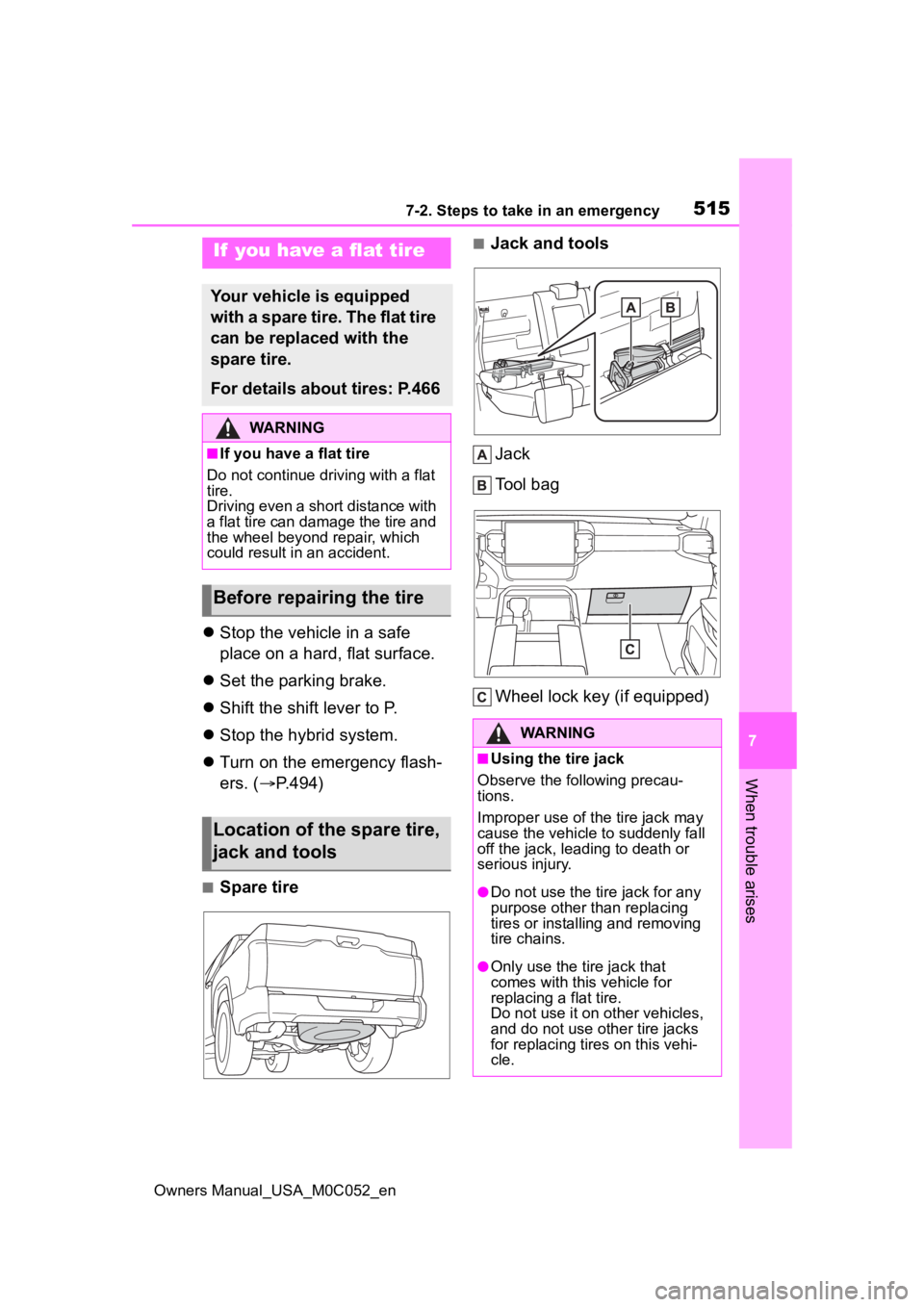
■Spare tire
■Jack and tools
Jack
Tool bag
Wheel lock key (if equipped)If you have a flat tire
Your vehicle is equipped
with a spare tire. The flat tire
can be replaced with the
spare tire.
For details about tires: P.466
WARNING
■If you have a flat tire
Do not continue driving with a flat
tire.
Driving even a short distance with
a flat tire can damage the tire and
the wheel beyond repair, which
could result in an accident.
Before repairing the tire
Location of the spare tire,
jack and tools
WARNING
■Using the tire jack
Observe the following precau-
tions.
Improper use of the tire jack may
cause the vehicle to suddenly fall
off the jack, leading to death or
serious injury.
●Do not use the tire jack for any
purpose other than replacing
tires or installing and removing
tire chains.
●Only use the tire jack that
comes with this vehicle for
replacing a flat tire.
Do not use it on other vehicles,
and do not use other tire jacks
for replacing tires on this vehi-
cle.
Page 514 of 618
5167-2. Steps to take in an emergency
Owners Manual_USA_M0C052_en
When replacing tires on a vehi-
cle with wheel lock nuts, use the
following procedures to remove
and install the wheel lock nuts.
The wheel lock key is stored in
the glove box. Always return the
wheel lock key to its original
position after use, so that it does not get lost. (
P.515)
■Removal
For ease of removal, the wheel
lock nut should always be the
first one loosened.
1 Place the wheel lock key on
top of the wheel lock nut,
turning until the wheel lock
key and wheel lock nut pat-
terns engage.
2 Place the wheel nut wrench
on the wheel lock key, and
while applying pressure on
the wheel lock key, loosen
the wheel lock nut.
■Installation
For ease of installation, the
wheel lock nut should always be
the last one tightened.
1 By hand, install a wheel lock
nut on each wheel.
2 Place the wheel lock key on
top of the wheel lock nut,
turning until the wheel lock
key and wheel lock nut pat-
terns engage.
3 Place the wheel nut wrench
on the wheel lock key, and
while applying pressure on
the wheel lock key, tighten
the wheel lock nut to the rec-
ommended torque.
WARNING
●Put the jack prope rly in its jack
point.
●Do not put any part of your body
under the vehicle while it is sup-
ported by the jack.
●Do not start the hybrid system
or drive the vehicle while the
vehicle is suppor ted by the jack.
●Do not raise the vehicle while
someone is inside.
●When raising the vehicle, do not
put an object on or under the
jack.
●Do not raise the vehicle to a
height greater than that required
to replace the tire.
●Use a jack stand if it is neces-
sary to get under the vehicle.
●When lowering the vehicle,
make sure that there is no-one
near the vehicle. If there are
people nearby, warn them
vocally before lowering.
■Using the jack handle
Insert the square head securely
until you hear a click to prevent
the extension parts from coming
apart unexpectedly.
Wheel lock nut (if
equipped)
Page 516 of 618
5187-2. Steps to take in an emergency
Owners Manual_USA_M0C052_en
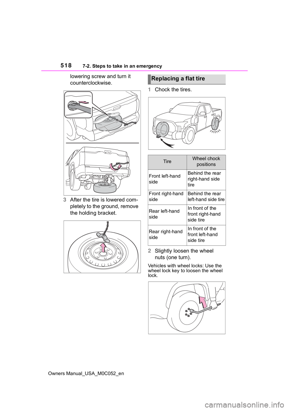
lowering screw and turn it
counterclockwise.
3 After the tire is lowered com-
pletely to the ground, remove
the holding bracket. 1
Chock the tires.
2 Slightly loosen the wheel
nuts (one turn).
Vehicles with wheel locks: Use the
wheel lock key to loosen the wheel
lock.
Replacing a flat tire
TireWheel chock
positions
Front left-hand
sideBehind the rear
right-hand side
tire
Front right-hand
sideBehind the rear
left-hand side tire
Rear left-hand
sideIn front of the
front right-hand
side tire
Rear right-hand
sideIn front of the
front left-hand
side tire
Page 520 of 618
5227-2. Steps to take in an emergency
Owners Manual_USA_M0C052_en
4While raising, secure the tire,
taking care that the tire goes
straight up without catching
on any surrounding part, to
prevent it from flying forward
during a collision or sudden
braking.
Tightening torque:
34.7 ft•lbf (46.6 N•m, 4.8 kgf•m)
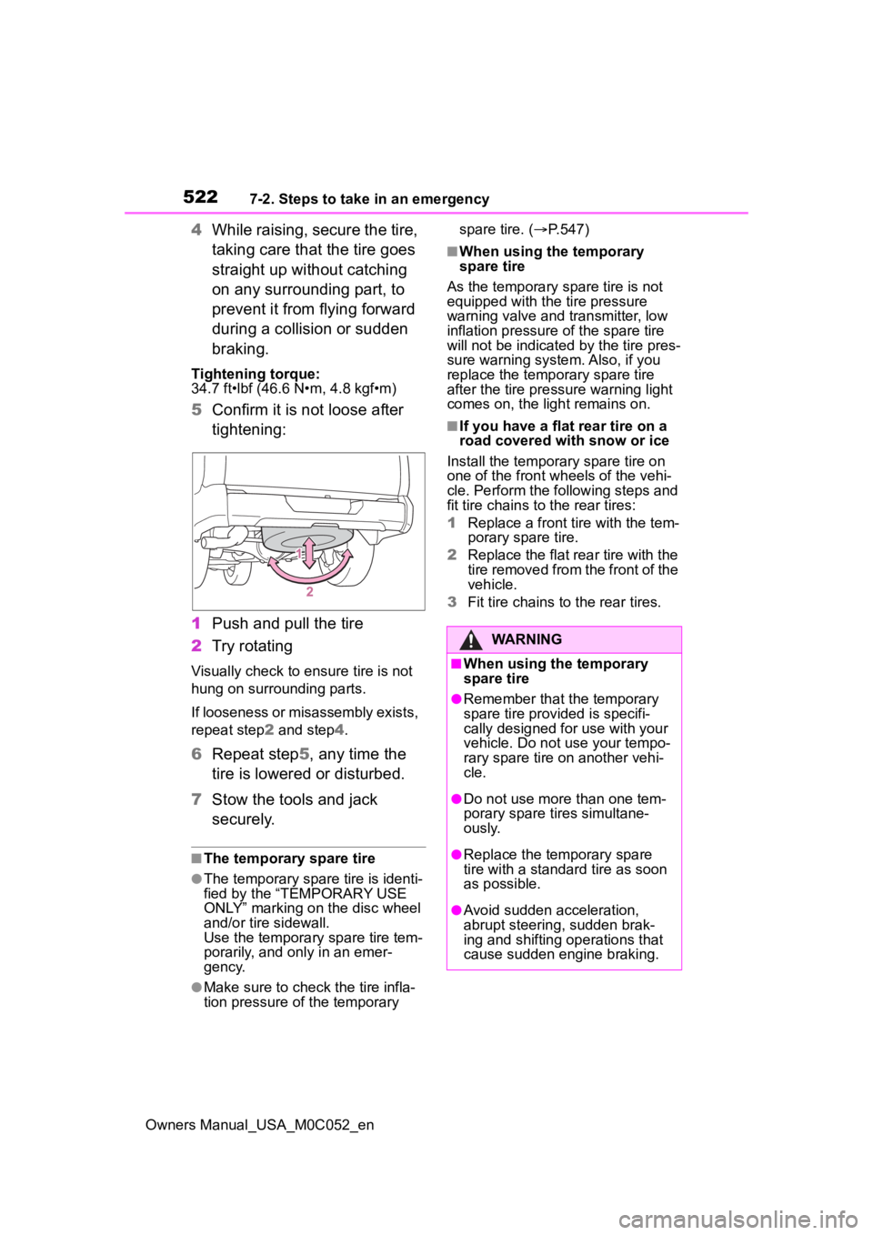
5Confirm it is not loose after
tightening:
1 Push and pull the tire
2 Try rotating
Visually check to ensure tire is not
hung on surrounding parts.
If looseness or misassembly exists,
repeat step 2 and step 4.
6 Repeat step5, any time the
tire is lowered or disturbed.
7 Stow the tools and jack
securely.
■The temporary spare tire
●The temporary spare tire is identi-
fied by the “TEMPORARY USE
ONLY” marking on the disc wheel
and/or tire sidewall.
Use the temporary spare tire tem-
porarily, and only in an emer-
gency.
●Make sure to check the tire infla-
tion pressure of the temporary spare tire. (
P.547)
■When using the temporary
spare tire
As the temporary spare tire is not
equipped with the tire pressure
warning valve and transmitter, low
inflation pressure of the spare tire
will not be indicated by the tire pres-
sure warning system. Also, if you
replace the temporary spare tire
after the tire pressure warning light
comes on, the light remains on.
■If you have a flat rear tire on a
road covered with snow or ice
Install the temporary spare tire on
one of the front w heels of the vehi-
cle. Perform the following steps and
fit tire chains to the rear tires:
1 Replace a front tire with the tem-
porary spare tire.
2 Replace the flat rear tire with the
tire removed from the front of the
vehicle.
3 Fit tire chains to the rear tires.
WARNING
■When using the temporary
spare tire
●Remember that t he temporary
spare tire provided is specifi-
cally designed for use with your
vehicle. Do not use your tempo-
rary spare tire on another vehi-
cle.
●Do not use more than one tem-
porary spare tires simultane-
ously.
●Replace the temporary spare
tire with a standa rd tire as soon
as possible.
●Avoid sudden acceleration,
abrupt steering, sudden brak-
ing and shifting operations that
cause sudden engine braking.
Page 521 of 618
5237-2. Steps to take in an emergency
Owners Manual_USA_M0C052_en
7
When trouble arises
WARNING
■When the spare tire is
attached
The vehicle speed may not be
correctly detecte d, and the follow-
ing systems may not operate cor-
rectly:
• ABS & Brake assist
• VSC
• TRAC
• AUTO LSD (if equipped)
• PCS (Pre-Collision System)
• Automatic High Beam (if equipped)
• LTA (Lane Tracing Assist)
• Dynamic radar cruise control with full-speed range
• EPS
• Trailer Sway Control
• Tire pressure warning system
• BSM (Blind Spot Monitor)
• Panoramic view monitor (if equipped)
• Multi-terrain Monitor (if equipped)
• Toyota parking assist monitor (if equipped)
• Intuitive parking assist
• PKSB (Parking Support Brake)
• Navigation system (if equipped)
Also, not only can the following
system not be utilized fully, but it
may even negatively affect the
drive-train components:
• 4WD system (if equipped)
■Speed limit when using the
temporary spare tire
Do not drive at speeds in excess
of 50 mph (80 km/h) when a tem-
porary spare tire is installed on
the vehicle.
The temporary spare tire is not
designed for driving at high
speeds. Failure to observe this
precaution may lead to an acci-
dent causing death or serious
injury.
NOTICE
■Do not drive the vehicle with
a flat tire
Do not continue driving with a flat
tire.
Driving even a short distance with
a flat tire can damage the tire and
the wheel beyond repair.
■Driving with tire chains and
the temporary spare tire
Do not fit tire chains to the tempo-
rary spare tire.
Tire chains may damage the vehi-
cle body and adversely affect driv-
ing performance.
■When stowing the flat tire
Ensure that ther e is no object
caught between t he tire and the
vehicle underbody.
■When replacing the tires
When removing or fitting the
wheels, tires or th e tire pressure
warning valve and transmitter,
contact your Toyota dealer as the
tire pressure warning valve and
transmitter may be damaged if not
handled correctly.
Page 536 of 618
5387-2. Steps to take in an emergency
Owners Manual_USA_M0C052_en
1Stop the hybrid system. Set
the parking brake and shift
the shift lever to P.
2 Remove the mud, snow or
sand from around the rear
wheels.
3 Place wood, stones or some
other material under the rear
wheels to help provide trac-
tion.
4 Restart the hybrid system.
5 Shift the shift lever to D or R
and release the parking
brake. Then, while exercising
caution, depress the acceler-
ator pedal.
■When it is difficult to free the
vehicle
Try the followings.
●Turn off the TRAC
( P.375)
●Using the rear d ifferential lock*
( P.364)
●Switching the front-wheel drive
control switch* ( P.361)
●Using Crawl Control* ( P.365)
●Using Multi-te rrain Select*
( P.369)
*: If equippedIf the vehicle becomes
stuck
Carry out the following pro-
cedures if the tires spin or
the vehicle becomes stuck
in mud, dirt or snow:
Recovering procedure
WARNING
■When attempting to free a
stuck vehicle
If you choose to push the vehicle
back and forth to free it, make
sure the surrounding area is clear
to avoid striking other vehicles,
objects or people. The vehicle
may also lunge forward or lunge
back suddenly as it becomes free.
Use extreme caution.
■When shifting the shift lever
Be careful not to shift the shift
lever with the accelerator pedal
depressed.
This may lead to unexpected
rapid acceleration of the vehicle
that may cause an accident
resulting in death o r serious injury.
NOTICE
■To avoid damaging the trans-
mission and other compo-
nents
●Avoid spinning the rear wheels
and depressing the accelerator
pedal more than necessary.
●If the vehicle remains stuck
even after these procedures are
performed, the vehicle may
require towing to be freed.
Page 538 of 618
5408-1. Specifications
Owners Manual_USA_M0C052_en
8-1.Specifications
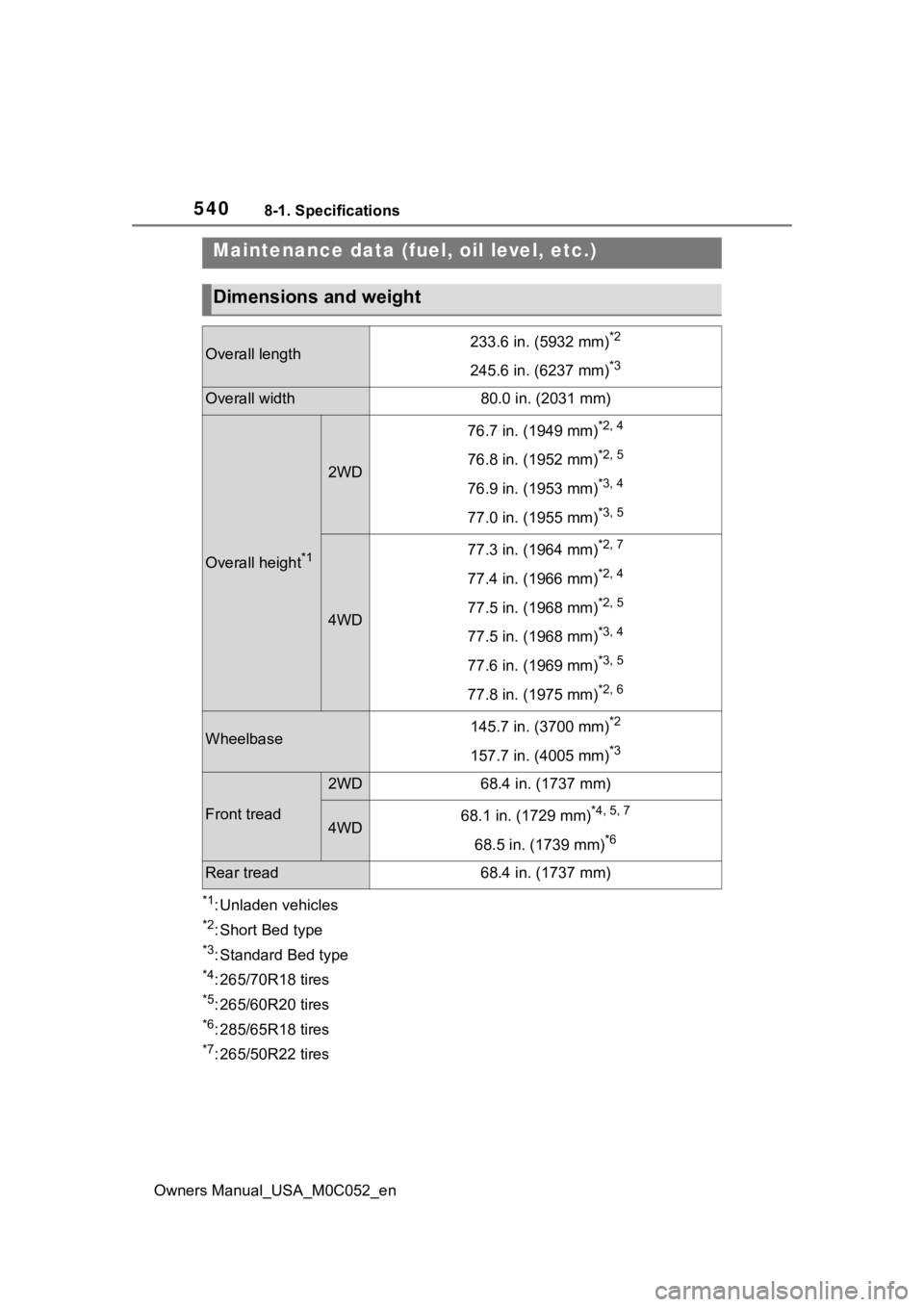
*1: Unladen vehicles
*2: Short Bed type
*3: Standard Bed type
*4: 265/70R18 tires
*5: 265/60R20 tires
*6: 285/65R18 tires
*7: 265/50R22 tires
Maintenance data (fuel, oil level, etc.)
Dimensions and weight
Overall length233.6 in. (5932 mm)*2
245.6 in. (6237 mm)*3
Overall width80.0 in. (2031 mm)
Overall height*1
2WD
76.7 in. (1949 mm)*2, 4
76.8 in. (1952 mm)*2, 5
76.9 in. (1953 mm)*3, 4
77.0 in. (1955 mm)*3, 5
4WD
77.3 in. (1964 mm)*2, 7
77.4 in. (1966 mm)*2, 4
77.5 in. (1968 mm)*2, 5
77.5 in. (1968 mm)*3, 4
77.6 in. (1969 mm)*3, 5
77.8 in. (1975 mm)*2, 6
Wheelbase145.7 in. (3700 mm)*2
157.7 in. (4005 mm)*3
Front tread
2WD68.4 in. (1737 mm)
4WD68.1 in. (1729 mm)*4, 5, 7
68.5 in. (1739 mm)*6
Rear tread68.4 in. (1737 mm)