2023 TOYOTA TUNDRA HYBRID flat tire
[x] Cancel search: flat tirePage 517 of 618
5197-2. Steps to take in an emergency
Owners Manual_USA_M0C052_en
7
When trouble arises
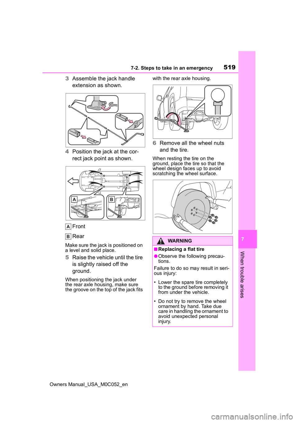
3 Assemble the jack handle
extension as shown.
4 Position the jack at the cor-
rect jack point as shown.
Front
Rear
Make sure the jack is positioned on
a level and solid place.
5Raise the vehicle until the tire
is slightly raised off the
ground.
When positioning the jack under
the rear axle housing, make sure
the groove on the top of the jack fits with the rear axle housing.
6
Remove all the wheel nuts
and the tire.
When resting the tire on the
ground, place the tire so that the
wheel design faces up to avoid
scratching the wheel surface.
WARNING
■Replacing a flat tire
●Observe the fo llowing precau-
tions.
Failure to do so may result in seri-
ous injury:
• Lower the spare tire completely to the ground before removing it
from under the vehicle.
• Do not try to remove the wheel ornament by hand. Take due
care in handling the ornament to
avoid unexpected personal
injury.
Page 519 of 618
5217-2. Steps to take in an emergency
Owners Manual_USA_M0C052_en
7
When trouble arises
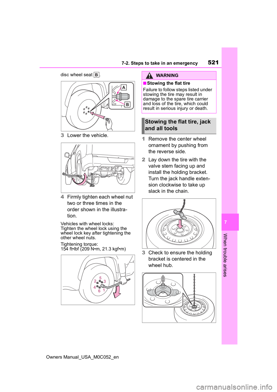
disc wheel seat .
3 Lower the vehicle.
4 Firmly tighten each wheel nut
two or three times in the
order shown in the illustra-
tion.
Vehicles with wheel locks:
Tighten the wheel lock using the
wheel lock key after tightening the
other wheel nuts.
Tightening torque:
154 ft•lbf (209 N•m, 21.3 kgf•m)
1Remove the center wheel
ornament by pushing from
the reverse side.
2 Lay down the tire with the
valve stem facing up and
install the holding bracket.
Turn the jack handle exten-
sion clockwise to take up
slack in the chain.
3 Check to ensure the holding
bracket is centered in the
wheel hub.
WARNING
■Stowing the flat tire
Failure to follow steps listed under
stowing the tire may result in
damage to the spare tire carrier
and loss of the tire, which could
result in serious injury or death.
Stowing the flat tire, jack
and all tools
Page 520 of 618
5227-2. Steps to take in an emergency
Owners Manual_USA_M0C052_en
4While raising, secure the tire,
taking care that the tire goes
straight up without catching
on any surrounding part, to
prevent it from flying forward
during a collision or sudden
braking.
Tightening torque:
34.7 ft•lbf (46.6 N•m, 4.8 kgf•m)
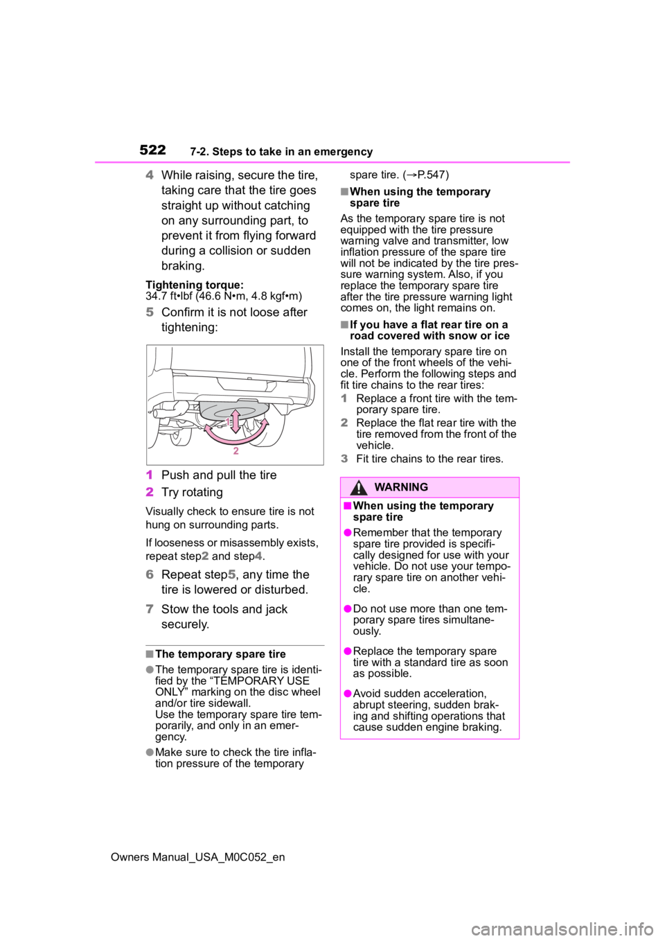
5Confirm it is not loose after
tightening:
1 Push and pull the tire
2 Try rotating
Visually check to ensure tire is not
hung on surrounding parts.
If looseness or misassembly exists,
repeat step 2 and step 4.
6 Repeat step5, any time the
tire is lowered or disturbed.
7 Stow the tools and jack
securely.
■The temporary spare tire
●The temporary spare tire is identi-
fied by the “TEMPORARY USE
ONLY” marking on the disc wheel
and/or tire sidewall.
Use the temporary spare tire tem-
porarily, and only in an emer-
gency.
●Make sure to check the tire infla-
tion pressure of the temporary spare tire. (
P.547)
■When using the temporary
spare tire
As the temporary spare tire is not
equipped with the tire pressure
warning valve and transmitter, low
inflation pressure of the spare tire
will not be indicated by the tire pres-
sure warning system. Also, if you
replace the temporary spare tire
after the tire pressure warning light
comes on, the light remains on.
■If you have a flat rear tire on a
road covered with snow or ice
Install the temporary spare tire on
one of the front w heels of the vehi-
cle. Perform the following steps and
fit tire chains to the rear tires:
1 Replace a front tire with the tem-
porary spare tire.
2 Replace the flat rear tire with the
tire removed from the front of the
vehicle.
3 Fit tire chains to the rear tires.
WARNING
■When using the temporary
spare tire
●Remember that t he temporary
spare tire provided is specifi-
cally designed for use with your
vehicle. Do not use your tempo-
rary spare tire on another vehi-
cle.
●Do not use more than one tem-
porary spare tires simultane-
ously.
●Replace the temporary spare
tire with a standa rd tire as soon
as possible.
●Avoid sudden acceleration,
abrupt steering, sudden brak-
ing and shifting operations that
cause sudden engine braking.
Page 521 of 618
5237-2. Steps to take in an emergency
Owners Manual_USA_M0C052_en
7
When trouble arises
WARNING
■When the spare tire is
attached
The vehicle speed may not be
correctly detecte d, and the follow-
ing systems may not operate cor-
rectly:
• ABS & Brake assist
• VSC
• TRAC
• AUTO LSD (if equipped)
• PCS (Pre-Collision System)
• Automatic High Beam (if equipped)
• LTA (Lane Tracing Assist)
• Dynamic radar cruise control with full-speed range
• EPS
• Trailer Sway Control
• Tire pressure warning system
• BSM (Blind Spot Monitor)
• Panoramic view monitor (if equipped)
• Multi-terrain Monitor (if equipped)
• Toyota parking assist monitor (if equipped)
• Intuitive parking assist
• PKSB (Parking Support Brake)
• Navigation system (if equipped)
Also, not only can the following
system not be utilized fully, but it
may even negatively affect the
drive-train components:
• 4WD system (if equipped)
■Speed limit when using the
temporary spare tire
Do not drive at speeds in excess
of 50 mph (80 km/h) when a tem-
porary spare tire is installed on
the vehicle.
The temporary spare tire is not
designed for driving at high
speeds. Failure to observe this
precaution may lead to an acci-
dent causing death or serious
injury.
NOTICE
■Do not drive the vehicle with
a flat tire
Do not continue driving with a flat
tire.
Driving even a short distance with
a flat tire can damage the tire and
the wheel beyond repair.
■Driving with tire chains and
the temporary spare tire
Do not fit tire chains to the tempo-
rary spare tire.
Tire chains may damage the vehi-
cle body and adversely affect driv-
ing performance.
■When stowing the flat tire
Ensure that ther e is no object
caught between t he tire and the
vehicle underbody.
■When replacing the tires
When removing or fitting the
wheels, tires or th e tire pressure
warning valve and transmitter,
contact your Toyota dealer as the
tire pressure warning valve and
transmitter may be damaged if not
handled correctly.
Page 545 of 618
5478-1. Specifications
Owners Manual_USA_M0C052_en
8
Vehicle specifications
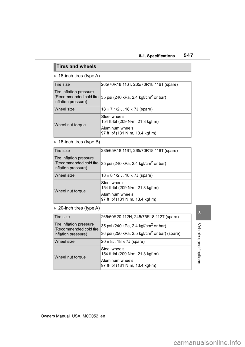
18-inch tires (type A)
18-inch tires (type B)
20-inch tires (type A)
Tires and wheels
Tire size265/70R18 116T, 265/70R18 116T (spare)
Tire inflation pressure
(Recommended cold tire
inflation pressure)
35 psi (240 kPa, 2.4 kgf/cm2 or bar)
Wheel size18 7 1/2 J, 18 7J (spare)
Wheel nut torque
Steel wheels:
154 ft·lbf (209 N·m, 21.3 kgf·m)
Aluminum wheels:
97 ft·lbf (131 N·m, 13.4 kgf·m)
Tire size285/65R18 116T, 265/70R18 116T (spare)
Tire inflation pressure
(Recommended cold tire
inflation pressure)
35 psi (240 kPa, 2.4 kgf/cm2 or bar)
Wheel size18 8 1/2 J, 18 7J (spare)
Wheel nut torque
Steel wheels:
154 ft·lbf (209 N·m, 21.3 kgf·m)
Aluminum wheels:
97 ft·lbf (131 N·m, 13.4 kgf·m)
Tire size265/60R20 112H, 245/75R18 112T (spare)
Tire inflation pressure
(Recommended cold tire
inflation pressure)35 psi (240 kPa, 2.4 kgf/cm2 or bar)
36 psi (250 kPa, 2.5 kgf/cm
2 or bar) (spare)
Wheel size20 8J, 18 7J (spare)
Wheel nut torque
Steel wheels:
154 ft·lbf (209 N·m, 21.3 kgf·m)
Aluminum wheels:
97 ft·lbf (131 N·m, 13.4 kgf·m)
Page 546 of 618
5488-1. Specifications
Owners Manual_USA_M0C052_en
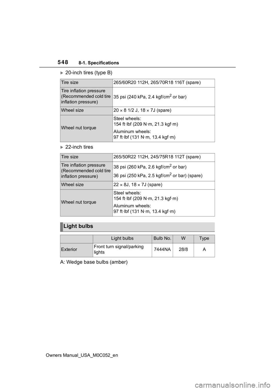
20-inch tires (type B)
22-inch tires
A: Wedge base bulbs (amber)
Tire size265/60R20 112H, 265/70R18 116T (spare)
Tire inflation pressure
(Recommended cold tire
inflation pressure)
35 psi (240 kPa, 2.4 kgf/cm2 or bar)
Wheel size20 8 1/2 J, 18 7J (spare)
Wheel nut torque
Steel wheels:
154 ft·lbf (209 N·m, 21.3 kgf·m)
Aluminum wheels:
97 ft·lbf (131 N·m, 13.4 kgf·m)
Tire size265/50R22 112H, 245/75R18 112T (spare)
Tire inflation pressure
(Recommended cold tire
inflation pressure)38 psi (260 kPa, 2.6 kgf/cm2 or bar)
36 psi (250 kPa, 2.5 kgf/cm
2 or bar) (spare)
Wheel size22 8J, 18 7J (spare)
Wheel nut torque
Steel wheels:
154 ft·lbf (209 N·m, 21.3 kgf·m)
Aluminum wheels:
97 ft·lbf (131 N·m, 13.4 kgf·m)
Light bulbs
Light bulbsBulb No.WTy pe
ExteriorFront turn signal/parking
lights7444NA28/8A
Page 549 of 618
5518-1. Specifications
Owners Manual_USA_M0C052_en
8
Vehicle specifications
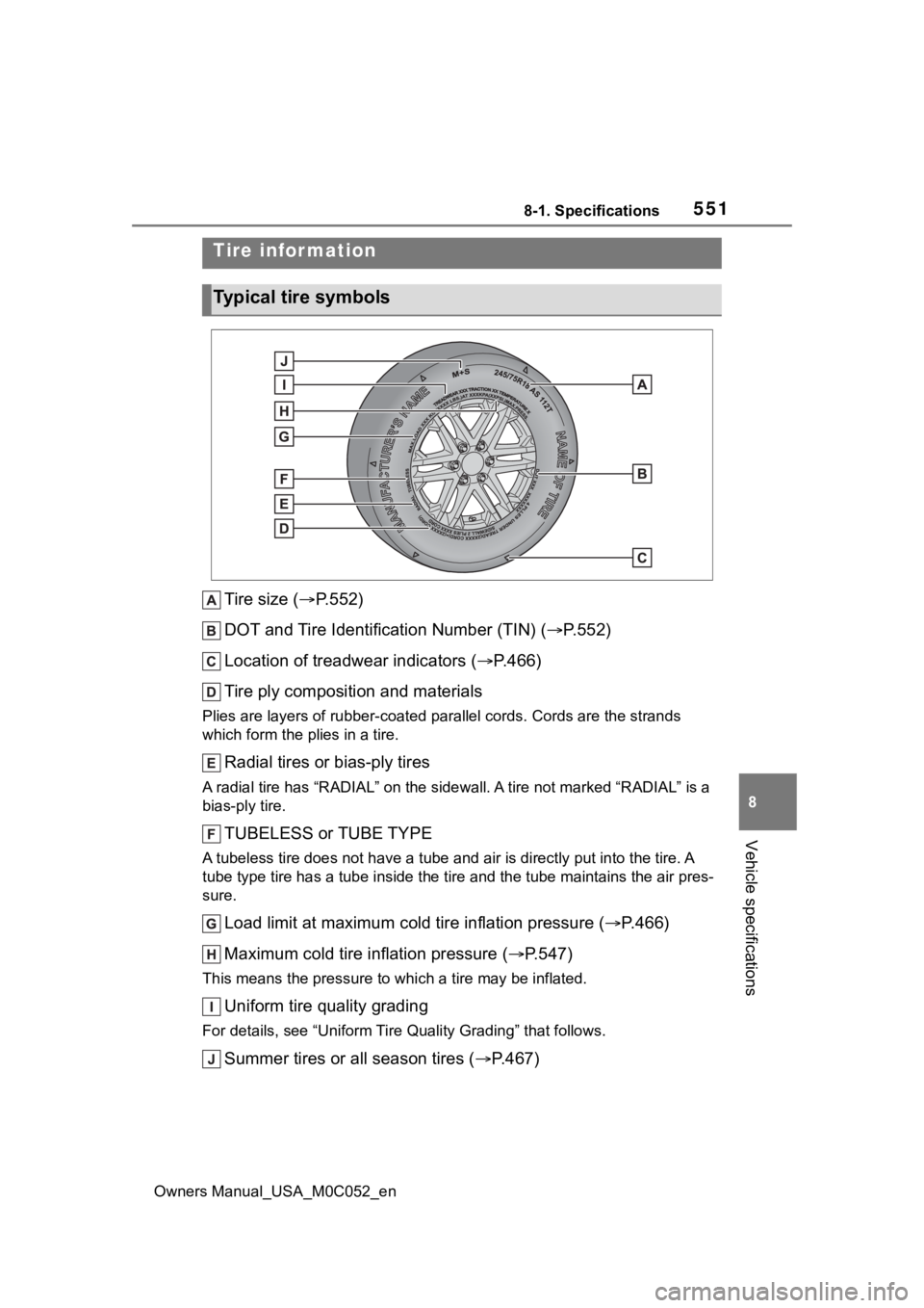
Tire size ( P.552)
DOT and Tire Identification Number (TIN) ( P.552)
Location of treadwear indicators ( P.466)
Tire ply composition and materials
Plies are layers of rubber-coat ed parallel cords. Cords are the strands
which form the pl ies in a tire.
Radial tires or bias-ply tires
A radial tire has “RADIAL” on the sidewall. A tire not marked “ RADIAL” is a
bias-ply tire.
TUBELESS or TUBE TYPE
A tubeless tire does not have a tube and air is directly put into the tire. A
tube type tire has a tube inside t he tire and the tube maintains the air pres-
sure.
Load limit at maximum cold tire inflation pressure (P.466)
Maximum cold tire inflation pressure ( P.547)
This means the pressure to w hich a tire may be inflated.
Uniform tire quality grading
For details, see “Uniform Tire Quality Grading” that follows.
Summer tires or all season tires ( P.467)
Tire information
Typical tire symbols
Page 552 of 618

5548-1. Specifications
Owners Manual_USA_M0C052_en
tion on uniform tire quality grad-
ing.
Your Toyota dealer will help answer
any questions you may have as you
read this information.
■DOT quality grades
All passenger vehicle tires must
conform to Federal Safety
Requirements in addition to
these grades. Quality grades
can be found where applicable
on the tire sidewall between
tread shoulder and maximum
section width.
For example: Treadwear 200 Trac-
tion AA Temperature A
■Treadwear
The treadwear grade is a com-
parative rating based on the
wear rate of the tire when tested
under controlled conditions on a
specified government test
course.
For example, a tire graded 150
would wear one and a half (1 - 1/2)
times as well on the government
course as a tire graded 100.
The relative perfo rmance of tires
depends upon the actual conditions
of their use. Performance may differ
significantly from the norm due to
variations in driving habits, service
practices and differences in road
characteristics and climate.
■Traction AA, A, B, C
The traction grades, from high-
est to lowest, are AA, A, B and
C, and they represent the tire’s
ability to stop on wet pavement as measured under controlled
conditions on specified govern-
ment test surfaces of asphalt
and concrete.
A tire marked C may have poor
traction performance.
Warning: The traction grade
assigned to this tire is based on
braking (straight ahead) traction
tests and does not include corner-
ing (turning) traction.
■Temperature A, B, C
The temperature grades are A
(the highest), B, and C, repre-
senting the tire’s resistance to
the generation of heat and its
ability to dissipate heat when
tested under controlled condi-
tions on a specified indoor labo-
ratory test wheel.
Sustained high temperature can
cause the material of the tire to
degenerate and reduce tire life, and
excessive temperature can lead to
sudden tire failure.
Grade C corresponds to a level of
performance which all passenger
car tires must meet under the Fed-
eral Motor Vehicle Safety Standard
No. 109.
Grades B and A represent higher
levels of performance on the labo-
ratory test wheel than the minimum
required by law.
Warning: The temperature grades
of a tire assume tha t it is properly
inflated and not overloaded.
Excessive speed, underinflation, or
excessive loading, either sepa-
rately or in combination, can cause