2023 TOYOTA TUNDRA HYBRID buttons
[x] Cancel search: buttonsPage 311 of 618
3114-5. Using the driving support systems
Owners Manual_USA_M0C052_en
4
Driving
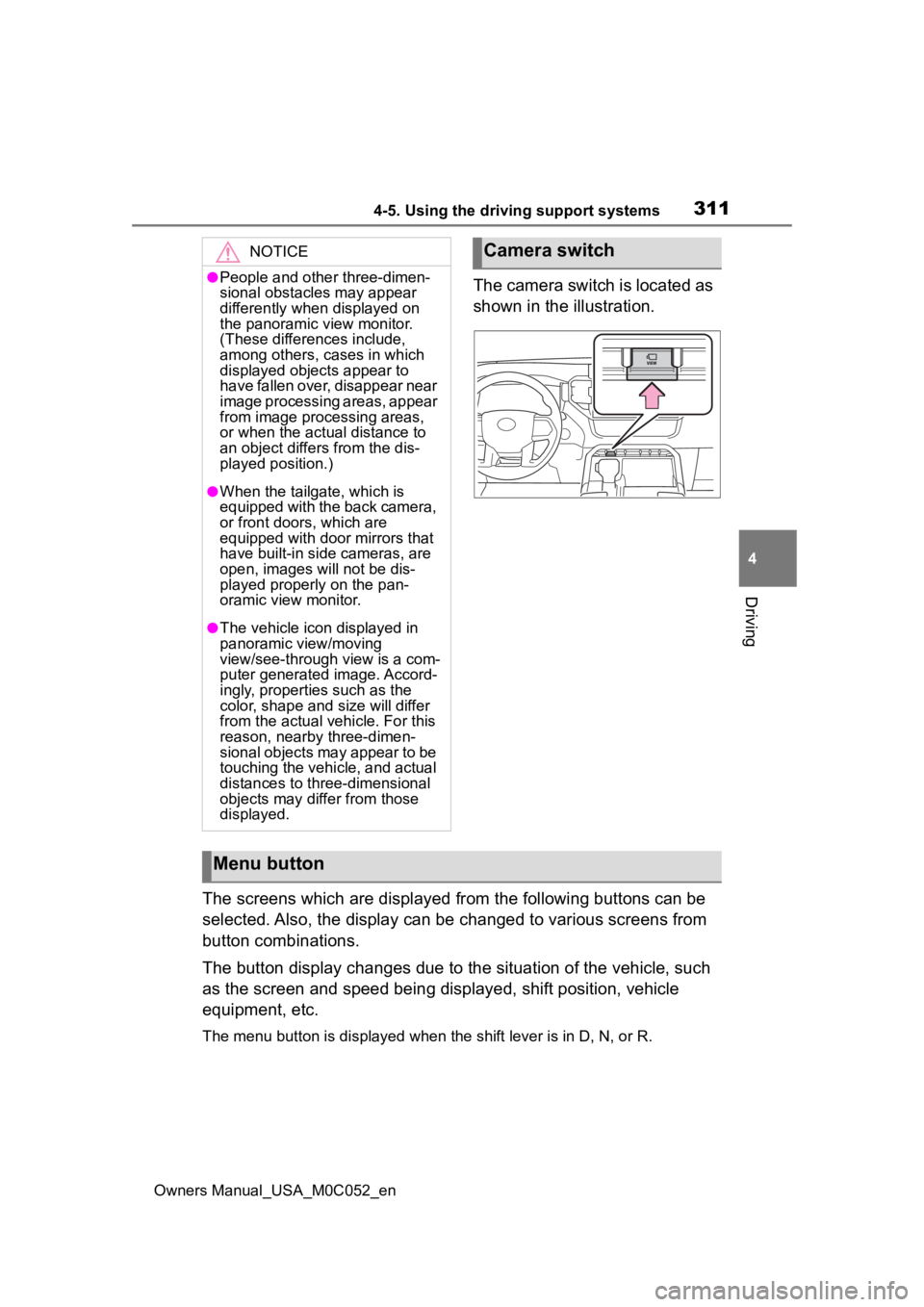
The camera switch is located as
shown in the illustration.
The screens which are displayed from the following buttons can be
selected. Also, the display can be changed to various screens f rom
button combinations.
The button display changes due to the situation of the vehicle, such
as the screen and speed being displayed, shift position, vehicle
equipment, etc.
The menu button is displayed whe n the shift lever is in D, N, or R.
NOTICE
●People and other three-dimen-
sional obstacles may appear
differently when displayed on
the panoramic view monitor.
(These differences include,
among others, cases in which
displayed objects appear to
have fallen over, disappear near
image processing areas, appear
from image processing areas,
or when the actual distance to
an object differs from the dis-
played position.)
●When the tailgate, which is
equipped with the back camera,
or front doors, which are
equipped with door mirrors that
have built-in side cameras, are
open, images will not be dis-
played properly on the pan-
oramic view monitor.
●The vehicle icon displayed in
panoramic view/moving
view/see-through view is a com-
puter generated image. Accord-
ingly, properties such as the
color, shape and size will differ
from the actual veh icle. For this
reason, nearby three-dimen-
sional objects may appear to be
touching the vehicle, and actual
distances to three-dimensional
objects may diffe r from those
displayed.
Camera switch
Menu button
Page 316 of 618
3164-5. Using the driving support systems
Owners Manual_USA_M0C052_enWhen a sensor detects an obstacle, the direction of and the app
roximate
distance to the obsta cle are displayed and the buzzer sounds.
Estimated course lines
Shows an estimated course when the steering wheel is turned.
• This line will be displayed when the steering wh eel is turned by 90° or
more from the cen ter (straight-line) position.
Guide line switching button
Select to change the guide line mode between the distance guide line mode
and the estimated course line mode. ( P.319)
Automatic display button
Select to turn automatic display mode on/off. (P.320)
Display mode switching buttons
The display can be changed to var ious screens from button combinations.
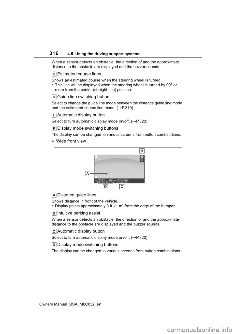
Wide front view
Distance guide lines
Shows distance in front of the vehicle.
• Display points approximately 3 ft. (1 m) from the edge of the bumper.
Intuitive parking assist
When a sensor detects an obstacle, the direction of and the app roximate
distance to the obsta cle are displayed and the buzzer sounds.
Automatic display button
Select to turn automatic display mode on/off. (P.320)
Display mode switching buttons
The display can be changed to var ious screens from button combinations.
Page 320 of 618
3204-5. Using the driving support systems
Owners Manual_USA_M0C052_en
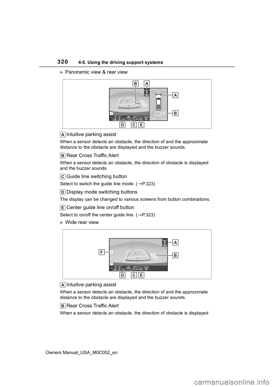
Panoramic view & rear viewIntuitive parking assist
When a sensor detects an obstacle, the direction of and the app roximate
distance to the obsta cle are displayed and the buzzer sounds.
Rear Cross Traffic Alert
When a sensor detects an obstacle, the direction of obstacle is displayed
and the buzzer sounds.
Guide line switching button
Select to switch the guide line mode. ( P.323)
Display mode switching buttons
The display can be changed to var ious screens from button combinations.
Center guide line on/off button
Select to on/off the center guide line. (P.323)
Wide rear view
Intuitive parking assist
When a sensor detects an obstacle, the direction of and the app roximate
distance to the obsta cle are displayed and the buzzer sounds.
Rear Cross Traffic Alert
When a sensor detects an obstacle, the direction of obstacle is displayed
Page 321 of 618
3214-5. Using the driving support systems
Owners Manual_USA_M0C052_en
4
Driving
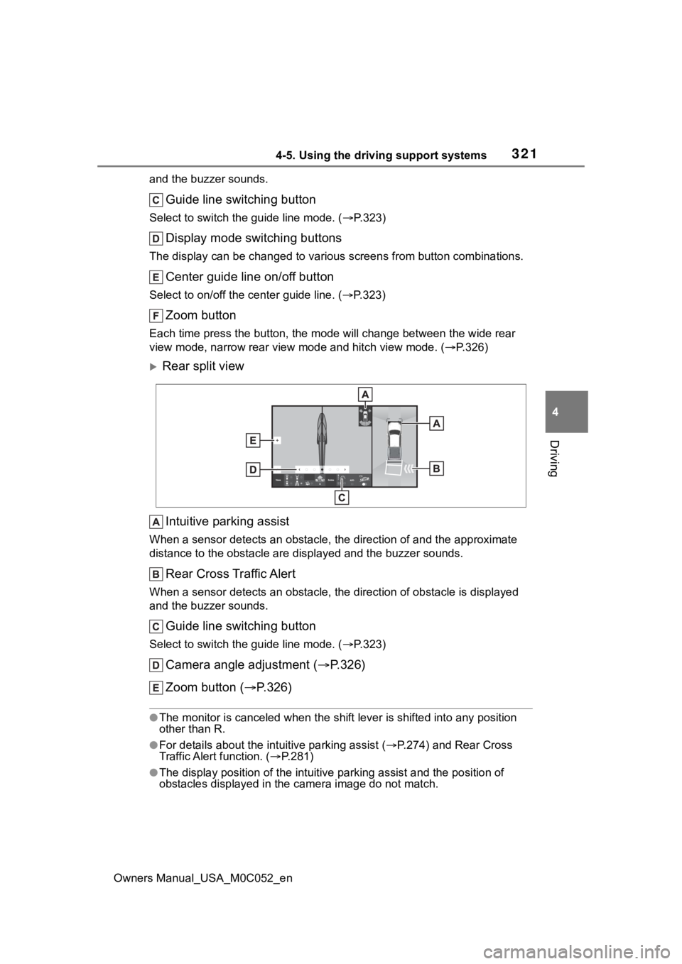
and the buzzer sounds.
Guide line switching button
Select to switch the guide line mode. ( P.323)
Display mode switching buttons
The display can be changed to var ious screens from button combinations.
Center guide line on/off button
Select to on/off the center guide line. (P.323)
Zoom button
Each time press the button, the mode will change between the wi de rear
view mode, narrow rear view mode and hitch view mode. (P.326)
Rear split view
Intuitive parking assist
When a sensor detects an obstacle, the direction of and the app roximate
distance to the obsta cle are displayed and the buzzer sounds.
Rear Cross Traffic Alert
When a sensor detects an obstacle, the direction of obstacle is displayed
and the buzzer sounds.
Guide line switching button
Select to switch the guide line mode. ( P.323)
Camera angle adjustment ( P.326)
Zoom button ( P.326)
●The monitor is canceled when the shift lever is shifted into any position
other than R.
●For details about the int uitive parking assist (P.274) and Rear Cross
Traffic Alert function. ( P.281)
●The display position of the intuitive parking assist and the po sition of
obstacles displayed in the camera image do not match.
Page 379 of 618
3794-5. Using the driving support systems
Owners Manual_USA_M0C052_en
4
Driving
*: If equipped
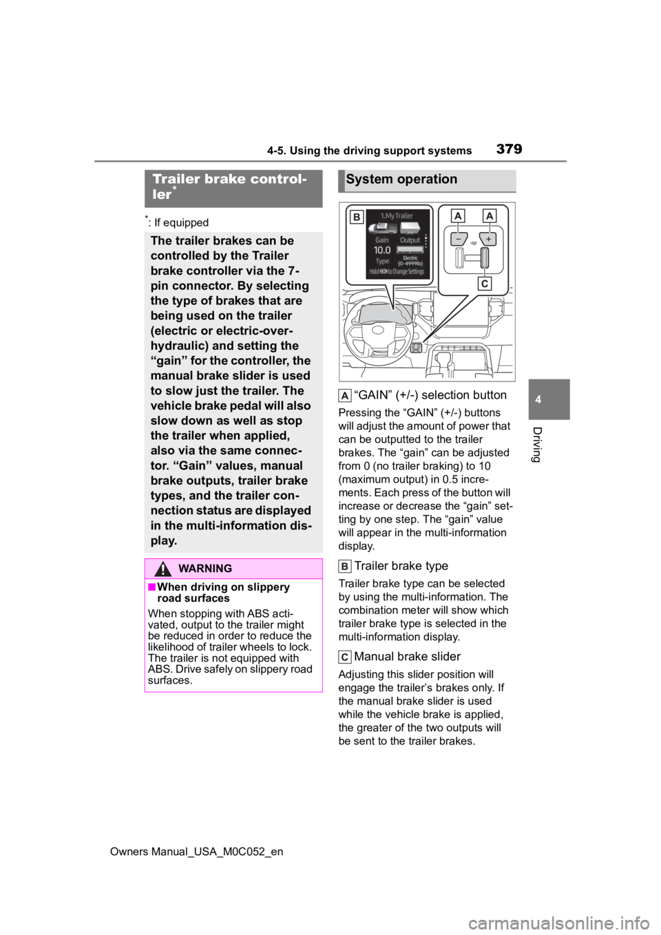
“GAIN” (+/-) selection button
Pressing the “GAIN” (+/-) buttons
will adjust the amount of power that
can be outputted to the trailer
brakes. The “gain” can be adjusted
from 0 (no trailer braking) to 10
(maximum output) in 0.5 incre-
ments. Each press of the button will
increase or decrease the “gain” set-
ting by one step. T he “gain” value
will appear in the mu lti-information
display.
Trailer brake type
Trailer brake type can be selected
by using the multi-information. The
combination meter will show which
trailer brake type is selected in the
multi-information display.
Manual brake slider
Adjusting this slider position will
engage the trailer’s brakes only. If
the manual brake slider is used
while the vehicle brake is applied,
the greater of the two outputs will
be sent to the trailer brakes.
Trailer brake control-
ler*
The trailer brakes can be
controlled by the Trailer
brake controller via the 7-
pin connector. By selecting
the type of brakes that are
being used on the trailer
(electric or electric-over-
hydraulic) and setting the
“gain” for the controller, the
manual brake slider is used
to slow just the trailer. The
vehicle brake pedal will also
slow down as well as stop
the trailer when applied,
also via the same connec-
tor. “Gain” values, manual
brake outputs, trailer brake
types, and the trailer con-
nection status are displayed
in the multi-information dis-
play.
WARNING
■When driving on slippery
road surfaces
When stopping with ABS acti-
vated, output to the trailer might
be reduced in order to reduce the
likelihood of trailer wheels to lock.
The trailer is not equipped with
ABS. Drive safely on slippery road
surfaces.
System operation
Page 380 of 618
3804-5. Using the driving support systems
Owners Manual_USA_M0C052_en
Select the item desired to be
setup and select as follows on
the multi-information screen
(P.100):
1 Press or on the meter
control switch and then select
.
2 Press or on the meter
control switch, select “Trailer
Settings”, and then press and
hold on the meter control
switch.
3 According to the display,
select the desired setting and
then press .
Changing trailer brake type or
trailer ID will cause the current
“gain” setting to reset to zero.
Make sure to set the “gain” as
described in the following sec-
tion.
“Gain” setting on trailer brake
controller should be set for a
specific towing condition. “Gain”
setting should be adjusted each
time the vehicle load, trailer
load, road conditions, or
weather changes. Setting the
“gain” value to 0 will disable the
trailer brake controller output. 1
Make sure the trailer brakes
are in good working condition
and functioning normally. See
trailer dealer if necessary.
2 Hook up the trailer and make
proper electrical connections.
3 Select the correct type of
trailer brakes that are
equipped on the trailer by
using the multi-information
display.
4 Drive vehicle with trailer
attached on a level road sur-
face similar to towing condi-
tion and in traffic-free
environment. Driving speed
should be approximately 20 -
25 mph [35 - 40 km/h].
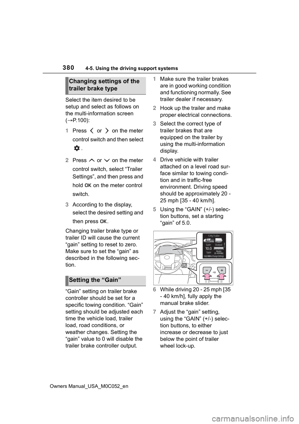
5 Using the “GAIN” (+/-) selec-
tion buttons, set a starting
“gain” of 5.0.
6 While driving 20 - 25 mph [35
- 40 km/h], fully apply the
manual brake slider.
7 Adjust the “gain” setting,
using the “GAIN” (+/-) selec-
tion buttons, to either
increase or decrease to just
below the point of trailer
wheel lock-up.
Changing settings of the
trailer brake type
Setting the “Gain”
Page 431 of 618
4335-4. Using the other interior features
Owners Manual_USA_M0C052_en
5
Interior features
■HomeLink® programming pro-
cedure
The programming procedures can
also be found at the following URL.
Website: www.homelink.com/toyota
For support, contact customer sup-
port at the following.
Help Line: 1-800-355-3515
The HomeLink® wireless control
system in your vehicle has 3
buttons which can be pro-
grammed to operate 3 different
devices. Refer to the program-
ming methods on the following
pages to determine the method
which is appropriate for the
device.
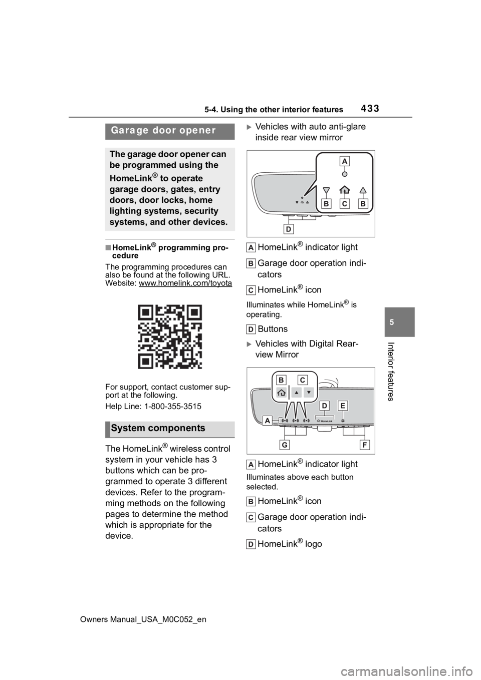
Vehicles with auto anti-glare
inside rear view mirror
HomeLink
® indicator light
Garage door operation indi-
cators
HomeLink
® icon
Illuminates while HomeLink® is
operating.
Buttons
Vehicles with Digital Rear-
view Mirror
HomeLink
® indicator light
Illuminates above each button
selected.
HomeLink® icon
Garage door operation indi-
cators
HomeLink
® logo
Garage door opener
The garage door opener can
be programmed using the
HomeLink
® to operate
garage doors, gates, entry
doors, door locks, home
lighting systems, security
systems, and other devices.
System components
Page 432 of 618
4345-4. Using the other interior features
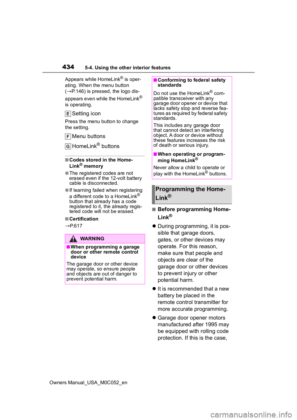
Owners Manual_USA_M0C052_enAppears while HomeLink
® is oper-
ating. When the menu button
( P.146) is pressed, the logo dis-
appears even while the HomeLink
®
is operating.
Setting icon
Press the menu button to change
the setting.
Menu buttons
HomeLink
® buttons
■Codes stored in the Home-
Link® memory
●The registered codes are not
erased even if the 12-volt battery
cable is disconnected.
●If learning failed when registering
a different code to a HomeLink®
button that already has a code
registered to it, the already regis-
tered code will not be erased.
■Certification
P. 6 1 7
■Before programming Home-
Link
®
During programming, it is pos-
sible that garage doors,
gates, or other devices may
operate. For this reason,
make sure that people and
objects are clear of the
garage door or other devices
to prevent injury or other
potential harm.
It is recommended that a new
battery be placed in the
remote control transmitter for
more accurate programming.
Garage door opener motors
manufactured after 1995 may
be equipped with rolling code
protection. If this is the case,
WARNING
■When programming a garage
door or other remote control
device
The garage door o r other device
may operate, so ensure people
and objects are out of danger to
prevent potential harm.
■Conforming to federal safety
standards
Do not use the HomeLink
® com-
patible transce iver with any
garage door opener or device that
lacks safety stop and reverse fea-
tures as required by federal safety
standards.
This includes any garage door
that cannot detect an interfering
object. A door or device without
these features increases the risk
of death or serious injury.
■When operating or program-
ming HomeLink®
Never allow a child to operate or
play with the HomeLink® buttons.
Programming the Home-
Link
®