2023 TOYOTA SUPRA flat tire
[x] Cancel search: flat tirePage 8 of 372

81-1. NOTES
assistance during driving, for
instance driver assistance sys-
tems. Furthermore, control units
facilitate comfort or infotainment
functions.
Information about stored or
exchanged data can be
requested from the manufac-
turer of the vehicle, in a sepa-
rate booklet, for example.
Each vehicle is marked with a
unique vehicle identification
number. Depending on the
country, the vehicle owner can
be identified with the vehicle
identification number, license
plate and corresponding authori-
ties. In addition, there are other
options to track data collected in
the vehicle to the driver or vehi-
cle owner, e.g. via the Toyota
Supra Connect account that is
used.
Control units process data to
operate the vehicle.
For example, this includes:
• Status messages for the vehi-cle and its Customize compo-
nents, e.g., wheel rotational
speed, wheel speed, deceler-
ation, transverse acceleration,
engaged safety belt indicator.
• Ambient conditions, e.g., tem- perature, rain sensor signals.
The processed data is only pro-
cessed in the vehicle itself and
generally volatile. The data is
not stored beyond the operating
period.
Electronic components, e.g.
control units and ignition keys,
contain components for storing
technical information. Informa-
tion about the vehicle condition,
component usage, mainte-
nance requirements or faults
can be stored temporarily or
permanently.
This information generally
records the state of a compo-
nent, a module, a system, or the
environment, for instance:
• Operating states of system components, e.g., fill levels,
tire inflation pressure, battery
status.
• Malfunctions and faults in important system compo-
nents, for instance lights and
brakes.
• Responses by the vehicle to special situations such as air-
bag deployment or engage-
ment of the driving stability
control systems.
• Information on vehicle-dam- aging events.
The data is required to perform
the control unit functions. Fur-
thermore, it also serves to rec-
ognize and correct malfunctions,
and helps the vehicle manufac-
Personal reference
Operating data in the vehi-
cle
Page 33 of 372

332-1. QUICK REFERENCE
2
QUICK REFERENCE
gasoline should be sulfur-free or
very low in sulfur content.
Fuels that are marked on the
gas pump as containing metal
must not be used. P.300
The tire inflation pressure speci-
fications can be found in the tire
inflation pressure table in the
printed Owner's Manual.
With Tire Pressure Monitor
TPM:
The corrected tire inflation pres-
sures are applied automatically.
Make sure that the correct tire
settings have been made.
With tires that cannot be found
in the tire pressure values on
the Control Display, reset the
Tire Pressure Monitor TPM.
Regularly check the tire inflation
pressure and correct it as
needed:
• At least twice a month.
• Before embarking on an extended trip. The friction during hard braking
may produce brake dust and
make the rims dirty. Brake dust
can be removed by cleaning the
rims. Toyota recommends using
vehicle care and cleaning prod-
ucts from Toyota.
Depending on the previous dis-
plays, the status display
appears when the engine is run-
ning or after the vehicle has
been driven for at least 30 min-
utes.
Via Toyota Supra Command:
1
"My Vehicle"
2 "Vehicle status"
3 "Engine oil level"
Different messages appear on
the Control Display depending
on the engine oil level. Pay
attention to these messages.
Safely park the vehicle and
Wheels and tires
Tire inflation pressure speci-
fications
After correcting the tire infla-
tion pressure
Checking the tire inflation
pressureCleaning the wheels
Electronic oil measure-
ment
Functional requirements
Displaying the engine oil
level
Adding engine oil
General information
Page 142 of 372

1423-1. CONTROLS
VSC Vehicle Stability Con-
trol System
The indicator light
flashes: VSC controls
the drive and braking
forces. The vehicle is
stabilized. Reduce
speed and modify your
driving style to the driv-
ing circumstances.
The indicator light lights
up: VSC has malfunc-
tioned.
Have the system imme-
diately checked by your
Toyota dealer.
VSC, refer to page 200.
VSC Vehicle Stability Con-
trol System is deactivated or
Traction mode is activated
VSC is deactivated or
Traction mode is acti-
vated.
VSC, refer to page 200,
and Traction mode,
refer to page 202.
Tire Pressure Monitor TPM
The indicator light lights
up: the Tire Pressure
Monitor reports a low
tire inflation pressure or
a flat tire. Follow the
information in the vehi-
cle message.
The indicator light
flashes and then con-
tinuously lights up: no
flat tire or loss of tire
inflation pressure can
be detected.
Interference caused
by systems or
devices with the
same radio fre-
quency: after leaving
the area of the inter-
ference, the system
automatically
becomes active
again.
A wheel without TPM
wheel electronics is
mounted: have it
checked by your Toy-
ota dealer as needed.
Malfunction: have the
system checked by
your Toyota dealer.
Tire Pressure Monitor,
refer to page 287.
Page 166 of 372

1663-1. CONTROLS
Do not hang pieces of cloth-
ing, such as jackets, over the
backrests.
Never modify either the indi-
vidual components or the wir-
ing in the airbag system. This
also applies to steering wheel
covers, the dashboard, and
the seats.
Do not remove the airbag sys-
tem.
Even when you follow all
instructions very closely, injury
from contact with the airbags
cannot be fully ruled out in cer-
tain situations.
The ignition and inflation noise
may lead to short-term and, in
most cases, temporary hearing
impairment in sensitive occu-
pants.
Vehicle modifications for a per-
son with disabilities may affect
the air bag system; contact the
Toyota dealer for further infor-
mation.
Warnings and information on the
airbags are also found on the
sun visors. Functional readiness of
the airbag system
Safety information
WARNING
Individual components can be hot
after triggering of the airbag sys-
tem. There is a risk of injury. Do
not touch individual components.
WARNING
Improperly executed work can
lead to failure, malfunction or
unintentional triggering of the air-
bag system. In the case of a mal-
function, the airbag system might
not trigger as intended despite the
accident severity. There is a risk
of injuries or danger to life. Have
the airbag system checked,
repaired, dismantled and
scrapped by your Toyota dealer.
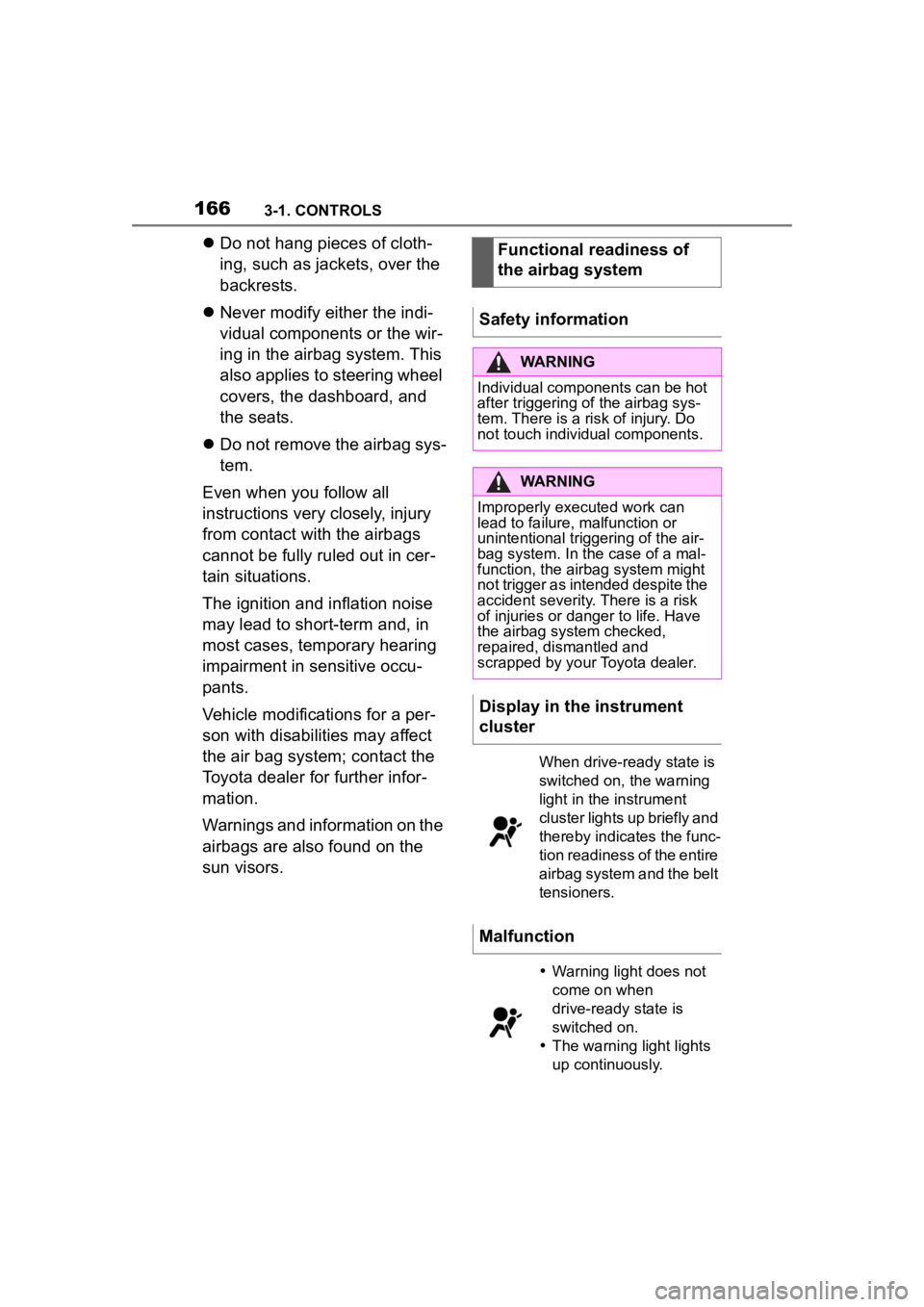
Display in the instrument
cluster
When drive-ready state is
switched on, the warning
light in the instrument
cluster lights up briefly and
thereby indicates the func-
tion readiness of the entire
airbag system and the belt
tensioners.
Malfunction
Warning light does not
come on when
drive-ready state is
switched on.
The warning light lights
up continuously.
Page 167 of 372

1673-1. CONTROLS
3
CONTROLS
Have the system checked.
The power that deploys the
driver's/front passenger airbags
depends on the position of the
driver's/front passenger seat.
To maintain the accuracy of this
function, calibrate the electrical
front seats as soon as a respec-
tive message appears on the
control display.
For further information:
Electrically adjustable seats,
see page P.101.
The airbags are not designed to
be used in place of the seat
belts.
The SRS front airbags and SRS
knee airbags are designed to
supplement the seat belts, not
be used in place of them, to
increase their effectiveness as
an occupant protection device.
SRS is an acronym for Supplemen-
tal Restraint System
In the event of a collision, the
seat belts restrain the occupants
in their seats, but if the impact of
the collision is especially
severe, there is danger of an
occupant’s head and chest con-
tacting the steering wheel, dash- board and windshield. In this
case, the SRS front airbags and
SRS knee airbags deploy
(inflate), instantly creating an air
cushion to help reduce the
impact on the occupants and
restrain them from contacting
the steering wheel, etc. with
their head, chest and knees.
The SRS front air bags and SRS
knee airbags deploy only when
an impact exceeding a certain
threshold is detected. In a colli-
sion, even if the impact is
severe enough to cause the
vehicle body to deform, the SRS
airbags may not deploy if the
impact of the collision is suffi-
ciently dispersed by the crash
structures of the vehicle body. If
the force of the collision does
not cause the airbags to deploy,
the seatbelts will protect the
occupants.
When an airbag deploys, as it
will inflate nearly instantly, it may
impact an occupant and cause
an injury, or the loud noise emit-
ted by ignition or deployment
may cause temporary partial
loss of hearing. Also, as an air-
bag and nearby parts will be
extremely hot after the airbag
deploys, touching them may
cause burns. For these reasons,
deployment of the airbags is not
entirely risk free. Therefore, in
order to reduce this risk, the air-
bags are designed to only
Setting the front seat posi-
tions
SRS front airbag/SRS knee
airbag
Page 172 of 372

1723-1. CONTROLS
ating an air cushion to help
reduce the impact on the occu-
pants and restrain them from
contacting the door window,
door, etc. with their head and
torso. When an airbag deploys,
as it will inflate nearly instantly, it
may impact an occupant and
cause an injury, or the loud
noise emitted by ignition or
deployment may cause tempo-
rary partial loss of hearing. Also,
as an airbag and nearby parts
will be extremely hot after the
airbag deploys, touching them
may cause burns. For these rea-
sons, deployment of the airbags
is not entirely risk free. There-
fore, in order to reduce this risk,
the airbags are designed to only
deploy when additional reduc-
tion of the impact applied to the
occupants in a collision is nec-
essary.
If the force of the collision does
not cause the airbags to deploy,
the seatbelts will protect the
occupants.
WARNING
Do not install seat covers which
are not designed for use with this
vehicle, or attach a cushion or any
other accessory to either front
seat or hang anything on either
front seatback. Do not place
objects around the side of either
front seat. Refer to P.164for the
installation position of the SRS
side airbags.
WARNING
Do not lean against the door or
door window.
Also, do not install a cup holder or
any other accessor ies near the
SRS side airbags.
If anything is attached to or left in
the deployment a rea of an SRS
side airbag, the airbag may be
prevented from deploying or the
object may become a projectile
when the airbag deploys, possibly
leading to injury. Also, if an occu-
pant is leaning into this area, the
airbag may strike and injure the
head or arm of the occupant when
deploying.
WARNING
When using a cup holder, use the
use the existing cup holders in the
vehicle. Do not place anything but
appropriately sized containers
into the cup holders. Refrain from
placing hot drinks or glass con-
tainers in the cup holders as they
may cause burns or other injuries
in the event of a collision or sud-
den braking.
Page 203 of 372

2033-1. CONTROLS
3
CONTROLS
TRACTION is displayed in the
instrument cluster.
In certain situations, the VSC is
activated automatically:
If Dynamic radar cruise con-
trol with full-speed range is
activated.
On a braking intervention by
the Toyota Supra Safety sys-
tems.
The vehicle has a flat tire.
*: if equipped
The active differential step-
lessly locks the rear axle
depending on the driving condi-
tions. This provides optimal
power transfer in all driving con-
ditions by helping prevent wheel
spin at either rear wheel.
The driver is responsible adapt-
ing his or her driving style to the
situation. This chapter describes all stan-
dard, country-specific and
optional features offered with
the series. It also describes fea-
tures and functions that are not
necessarily available in your
vehicle, e.g., due to the selected
options or country versions. This
also applies to safety-related
functions and systems. When
using these functions and sys-
tems, the applicable laws and
regulations must be observed.
Speed Limit Info shows the cur-
rent valid maximum speed in the
instrument cluster and the
Head-up Display.
The camera in the area of the
interior mirror detects traffic
signs at the edge of the road as
well as variable overhead sign
posts.
Traffic signs with extra symbols
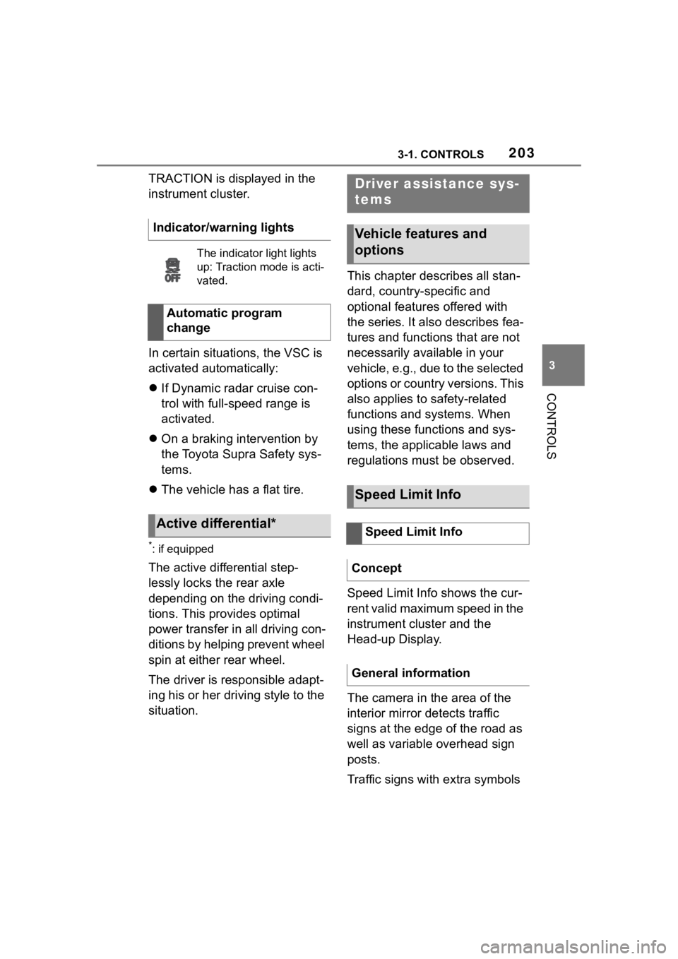
Indicator/warning lights
The indicator
light lights
up: Traction mode is acti-
vated.
Automatic program
change
Active differential*
Driver assistance sys-
tems
Vehicle features and
options
Speed Limit Info
Speed Limit Info
Concept
General information
Page 253 of 372

2533-1. CONTROLS
3
CONTROLS
This chapter describes all stan-
dard, country-specific and
optional features offered with
the series. It also describes fea-
tures and functions that are not
necessarily available in your
vehicle, e.g., due to the selected
options or country versions. This
also applies to safety-related
functions and systems. When
using these functions and sys-
tems, the applicable laws and
regulations must be observed.1Locate the statement “The
combined weight of occu-
pants and cargo should
never exceed XXX kg or XXX
lbs” on your vehicle’s plac-
ard.
2 Determine the combined
weight of the driver and pas-
sengers that will be riding in
your vehicle.
Cargo area
Vehicle features and
options
Loading
Safety information
WARNING
High gross weight can overheat
the tires, damage them internally
and cause a sudden drop in tire
inflation pressure. Driving charac-
teristics may be negatively
impacted, reducing lane stability,
lengthening the braking distances
and changing the steering
response. There is a risk of an
accident. Pay attention to the per-
mitted load capaci ty of the tires
and never exceed the permitted
gross weight.
WARNING
Loose object or devices with a
cable connection to the vehicle,
for instance mobile phones, can
be thrown about the car�