2023 TOYOTA RAV4 PRIME interior lights
[x] Cancel search: interior lightsPage 4 of 662

4TABLE OF CONTENTS
Parking Support Brake func-tion (rear-crossing vehicles).................................... 402
Driving mode select switch .................................... 404
Trail Mode ..................... 405
Driving assist systems .. 407
5-6. Driving tips Winter driving tips ......... 413
Utility vehicle precautions .................................... 416
6-1. Using the air conditioning
system and defogger
Automatic air conditioning
system ......................... 422
Remote Air Conditioning System ........................ 431
Heated steering wheel/Front seat heaters/Front seat
heaters and ventila-
tors/Rear seat heaters. 433
6-2. Using the interior lights Interior lights list ............ 436
6-3. Using the storage features List of storage features . 438
Luggage compartment fea- tures ............................ 442
6-4. Using the other interior fea- tures
Other interior features ... 445
Power outlet (AC 120 V/1500 W)................................ 455
When the power outlet (AC 120 V 1500 W) cannot be
used properly .............. 461Garage door opener ......
463
7-1. Maintenance and care Cleaning and protecting the vehicle exterior ............ 472
Cleaning and protecting the vehicle interior ............. 475
7-2. Maintenance Maintenance requirements.................................... 478
General maintenance .... 480
Emission inspection and maintenance (I/M) pro-
grams .......................... 482
7-3. Do-it-yourself maintenance Do-it-yourself service pre-cautions ....................... 484
Hood .............................. 486
Positioning a floor jack .. 487
Engine compartment ..... 489
12-volt battery................ 495
Tires .............................. 497
Tire inflation pressure .... 509
Wheels .......................... 511
Air conditioning filter ...... 513
Cleaning the DC/DC Con- verter air intake vent and fil-
ter ................................ 515
Wiper insert replacement .................................... 519
Electronic key battery .... 522
Checking and replacing fuses ............................ 524
Headlight aim ................ 527
Light bulb
s ..................... 528
6Interior features
7Maintenance and care
Page 23 of 662
23Pictorial index
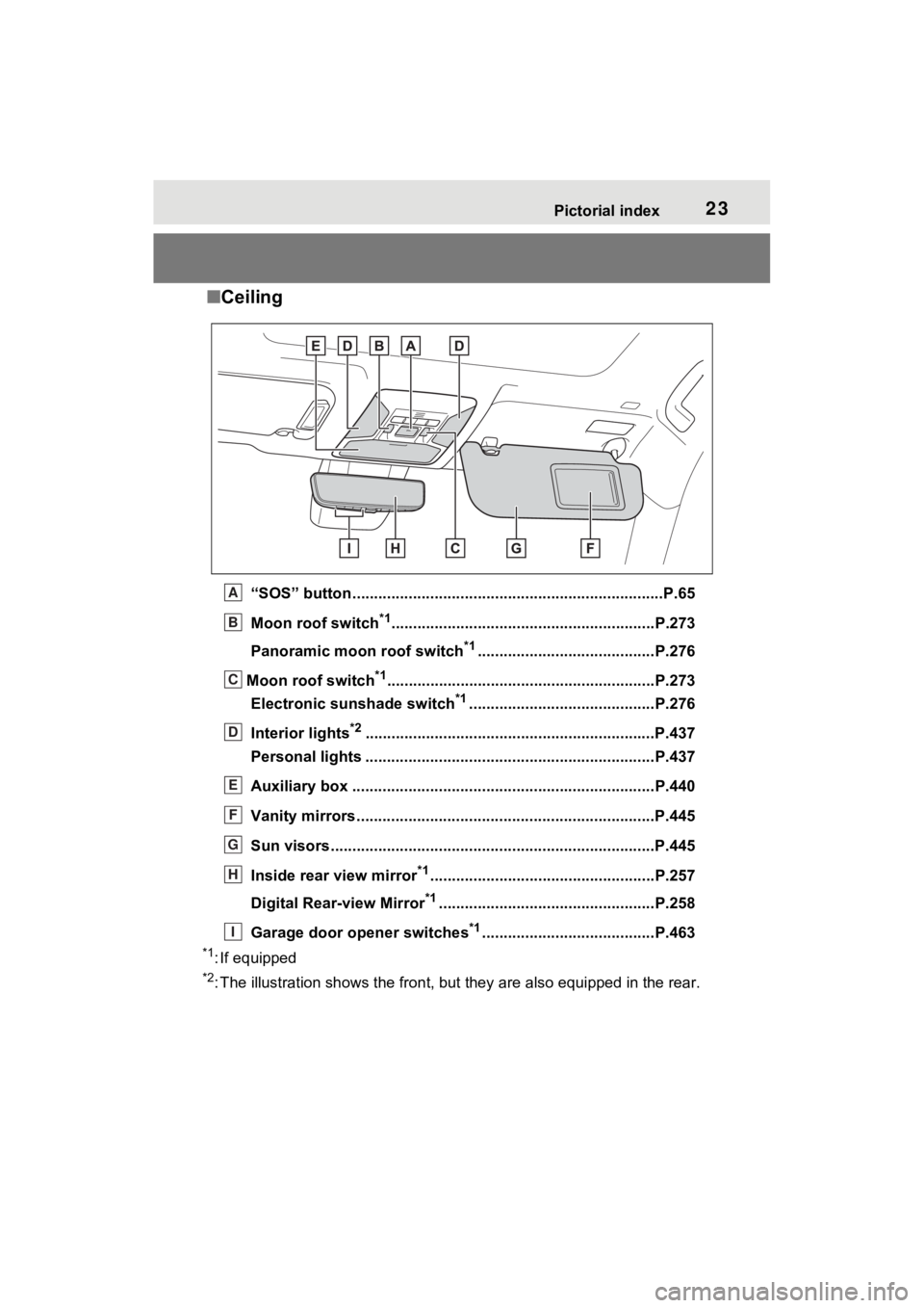
■Ceiling
“SOS” button ................................................... .....................P.65
Moon roof switch
*1.............................................................P. 273
Panoramic moon roof switch
*1.........................................P.276
Moon roof switch
*1..............................................................P .273
Electronic sunshade switch
*1...........................................P.276
Interior lights
*2............................................................... ....P.437
Personal lights ................................................ ...................P.437
Auxiliary box .................................................. ....................P.440
Vanity mirrors.....................................................................P.445
Sun visors...........................................................................P.445
Inside rear view mirror
*1....................................................P.257
Digital Rear-view Mirror
*1..................................................P.258
Garage door opener switches
*1........................................P.463
*1: If equipped
*2: The illustration shows the fron t, but they are also equipped i n the rear.
A
B
C
D
E
F
G
H
I
Page 35 of 662

351-1. For safe use
1
For safety and security
Driver airbag
Front passenger occupant classification sensors
Knee airbag
SRS warning light
Airbag sensor assembly
Your vehicle is equipped with ADVANCED AIRBAGS designed
based on the US motor vehicle safety standards (FMVSS208). The
airbag sensor assembly (ECU) cont rols airbag deployment based on
information obtained from the sensors etc. shown in the system
components diagram above. This in formation includes crash sever-
ity and occupant information. As the airbags deploy, a chemical
reaction in the inflators quickly fills the airbags with non-toxic gas to
help restrain the motion of the occupants.
■If the SRS airbags deploy
(inflate)
●Slight abrasions, burns, bruising
etc., may be sustained from SRS
airbags, due to the extremely high
speed deployment (inflation) by
hot gases.
●A loud noise and white powder will
be emitted.
●Parts of the airbag module (steer-
ing wheel hub, airbag cover and
inflator) as well as the front seats,
parts of the front and rear pillars,
and roof side rails, may be hot for
several minutes. T he airbag itself
may also be hot.
●The windshield may crack.
●The hybrid system will be stopped
and fuel supply to the engine will
be stopped. ( P.89)
●All of the doors will be unlocked.
( P.223)
●The brakes and st op lights will be
controlled automatically.
( P.408)
●The interior lights will turn on auto-
matically. ( P.436)
●The emergency flashers will turn
on automatically. ( P.534)
●For Safety Connect subscribers, if
any of the following situations
occur, the system is designed to
send an emergency call to the
response center, notifying them of
the vehicle’s location (without
needing to push the “SOS” button)
and an agent will attempt to speak
with the occupants to ascertain
the level of emergency and assis-
tance required. If the occupants
are unable to communicate, the
agent automatically treats the call
as an emergency and helps to dis-
patch the necessary emergency
services. ( P.65)
• An SRS airbag is deployed.
• A seat belt pretensioner is acti-
vated.
• The vehicle is involved in a severe
rear-end collision.
■SRS airbag deployment condi-
tions (SRS front airbags)
●The SRS front airbags will deploy
in the event of an impact that
exceeds the set threshold level
(the level of forc e corresponding
to an approximately 12 - 18 mph
[20 - 30 km/h] frontal collision with
a fixed wall that does not move or
deform).
However, this threshold velocity will
N
O
P
Q
R
Page 118 of 662
1182-2. Charging
This vehicle has been designed
to allow charging from an exter-
nal power source using a AC
charging cable for exclusive use
with standard household AC
outlets.
However, the vehicle differs
greatly from standard household
electrical goods in the following
ways, and incorrect usage could
cause fire or electric shock, pos-
sibly leading to death or serious
injury.
When charging, a large
amount of current will flow for
a long time.
Charging can be conducted
outdoors.
To charge properly, follow the
procedure after reading the
explanation below. Charging is
intended to be carried out by
licensed drivers only who prop-
erly understand the charging
procedure.
Do not allow children to use
the AC charging cable without supervision. Also, keep the
AC charging cable out of
reach of infants.
When charging with a char-
ger, follow the procedures for
using each charger.
When charging using a public
charging facility, check the
setting of the charging sched-
ule function.
• When the charging schedule is
registered, temporarily turn off
the function or turn “Charge Now”
on. ( P.135, 141, 147)
• When the charging schedule is set to on, charging will not start
even if the AC charging cable is
connected. Also, charging fee
may occur due to connection of
the AC charging cable.
Before charging, always check
the following items.
The parking brake is applied.
( P.314)
Lights such as the head-
lights, emergency flashers
and interior lights etc. are
turned off.
If these light swit ches are turned
on, then these features will con-
sume electricity, and charging time
will increase.
The power switch is turned to
OFF. ( P.307)
WARNING
■When the AC charging cable
is connected to the vehicle
Do not operate the shift lever.
In the unlikely event that the AC
charging cable has been dam-
aged, the shift position may
change from P to another position
and the vehicle could move, pos-
sibly leading to an accident.
Charging precautions
Confirm the following
before charging
Page 177 of 662

1773-1. Instrument cluster
3
Vehicle status information and indicators
●Displays the outside temperature
within the range of -40°F (-40°C)
to 122°F (50°C).
●When the outside temperature is
approximately 37°F (3°C) or
lower, the indicator will flash
for approximately 10 seconds,
then stay on.
■Liquid crystal display
P.185
■Customization
Settings (e. g. meter display) can be
changed on the screen of the
multi-informat ion display. (P.191)
Switches the items of the odom-
eter, trip meter A and trip meter
B by pressing the “ODO TRIP”
switch.
When the trip meter is dis-
played, pressing and holding the
switch will reset the trip meter.
The brightness of the instrument
panel lights can be adjusted by
turning the dial.
WARNING
■The information display at
low temperatures
Allow the interior of the vehicle to
warm up before u sing the liquid
crystal informat ion display. At
extremely low temperatures, the
display monitor may respond
slowly, and display changes may
be delayed.
For example, there is a lag
between the driver’s shifting and
the new shift range appearing on
the display. This lag could cause
the driver to downshift again,
causing rapid and excessive
engine braking and possibly an
accident resulting in death or
injury.
NOTICE
■To prevent damage to the
engine and its components
The engine may be overheating if
“Engine Coolant Temp High Stop
in a Safe Place See Owner’s
Manual” is shown on the multi-
information displa y. In this case,
immediately stop the vehicle in a
safe place, and c heck the engine
after it has cooled completely.
( P.574)
Using the “ODO TRIP”
switch
Instrument panel light
control
Page 242 of 662
2424-2. Opening, closing and locking the doors
●When an exterior alarm sounds
once for 5 seconds
●When an interior alarm pings con-
tinuously
■Battery-saving function
The battery-saving function will be
activated in order to prevent the
electronic key battery and the 12-
volt battery from being discharged
while the vehicle is not in operation
for a long time.
●In the following situations, the
smart key system may take some
time to unlock the doors. Also, the
interior lights may not turn on
when the doors are unlocked.
• The electronic key has been left in an area of approxi mately 11.5 ft.
(3.5 m) of the outside of the vehi-
cle for 40 seconds or longer.
• The smart key system has not been used for 5 days or longer.
●If the smart key system has not
been used for 14 days or longer,
the doors canno t be unlocked at
any doors except the driver’s
door. In this case, take hold of the driver’s door handle, or use the
wireless remote c
ontrol or the
mechanical key, to unlock the
doors.
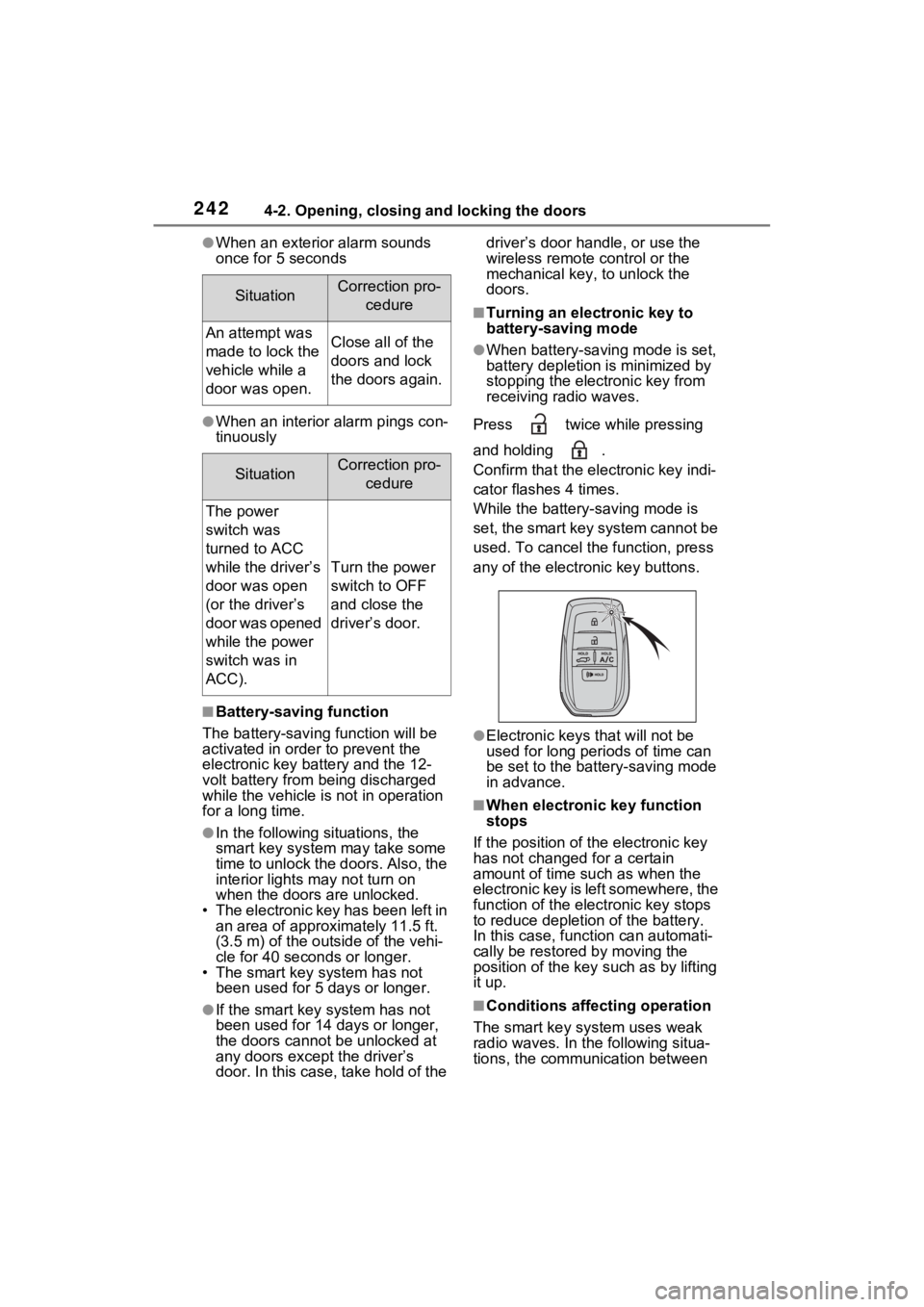
■Turning an electronic key to
battery-saving mode
●When battery-saving mode is set,
battery depletion is minimized by
stopping the electronic key from
receiving radio waves.
Press twice while pressing
and holding .
Confirm that the ele ctronic key indi-
cator flashes 4 times.
While the battery-saving mode is
set, the smart key system cannot be
used. To cancel the function, press
any of the electronic key buttons.
●Electronic keys that will not be
used for long periods of time can
be set to the battery-saving mode
in advance.
■When electronic key function
stops
If the position of the electronic key
has not changed for a certain
amount of time suc h as when the
electronic key is left somewhere, the
function of the elec tronic key stops
to reduce depletion of the battery.
In this case, funct ion can automati-
cally be restored by moving the
position of the key such as by lifting
it up.
■Conditions affecting operation
The smart key system uses weak
radio waves. In the following situa-
tions, the communication between
SituationCorrection pro- cedure
An attempt was
made to lock the
vehicle while a
door was open.Close all of the
doors and lock
the doors again.
SituationCorrection pro-cedure
The power
switch was
turned to ACC
while the driver’s
door was open
(or the driver’s
door was opened
while the power
switch was in
ACC).
Turn the power
switch to OFF
and close the
driver’s door.
Page 419 of 662
421
6
6
Interior features
Interior features
6-1. Using the air conditioning system and defogger
Automatic air conditioning system ....................... 422
Remote Air Conditioning System ...................... 431
Heated steering wheel/Front seat heat-
ers/Front seat heaters and
ventilators/Rear seat heat-
ers ............................. 433
6-2. Using the interior lights Interior lights list .......... 436
6-3. Using the storage features List of storage features 438
Luggage compartment fea- tures .......................... 442
6-4. Using the other interior features
Other interior features . 445
Power outlet (AC 120 V/1500 W) ..... ............455
When the power outlet (AC 120 V 1500 W) cannot be
used properly ............ 461
Garage door opener.... 463
Page 434 of 662
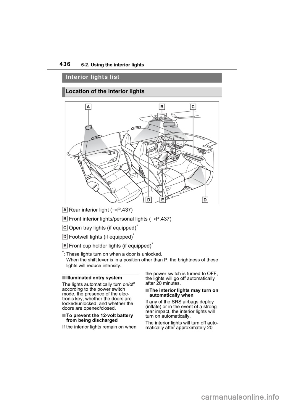
4366-2. Using the interior lights
6-2.Using the interior lights
Rear interior light (P.437)
Front interior lights/personal lights ( P.437)
Open tray lights (if equipped)
*
Footwell lights (if equipped)*
Front cup holder lights (if equipped)*
*: These lights turn on when a door is unlocked.
When the shift lever is in a pos ition other than P, the brightness of these
lights will reduce intensity.
■Illuminated entry system
The lights automati cally turn on/off
according to the power switch
mode, the presence of the elec-
tronic key, whether the doors are
locked/unlocked, and whether the
doors are opened/closed.
■To prevent the 12-volt battery
from being discharged
If the interior light s remain on when the power switch is turned to OFF,
the lights will go off automatically
after 20 minutes.
■The interior li
ghts may turn on
automatically when
If any of the SRS airbags deploy
(inflate) or in the event of a strong
rear impact, the in terior lights will
turn on automatically.
The interior lights will turn off auto-
matically after approximately 20
Interior lights list
Location of the i nterior lights
A
B
C
D
E