Page 181 of 662

1813-1. Instrument cluster
3
Vehicle status information and indicators
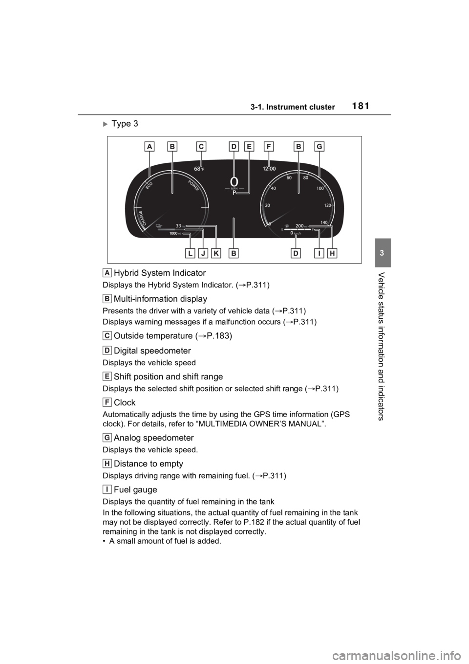
Type 3Hybrid System Indicator
Displays the Hybrid S ystem Indicator. (P.311)
Multi-information display
Presents the driver with a variety of vehicle data (P.311)
Displays warning messages if a malfunction occurs (P.311)
Outside temperature ( P.183)
Digital speedometer
Displays the vehicle speed
Shift position and shift range
Displays the selected shift posit ion or selected shift range (P.311)
Clock
Automatically adjusts the time by using the GPS time informatio n (GPS
clock). For details, refer to “MULTIMEDIA OWNER’S MANUAL”.
Analog speedometer
Displays the vehicle speed.
Distance to empty
Displays driving range with remaining fuel. ( P.311)
Fuel gauge
Displays the quantity of fu el remaining in the tank
In the following sit uations, the actual quantity of fuel remain ing in the tank
may not be displayed correctly. R efer to P.182 if the actual quantity of fuel
remaining in the tank is not displayed correctly.
• A small amount of fuel is added.
A
B
C
D
E
F
G
H
I
Page 196 of 662

1963-1. Instrument cluster
Select to set the items on the upper
and lower side of the drive informa-
tion screen from three items, aver-
age speed, distance and total time.
“Closing Display”
Select to set the i tems displayed
when the power switch is turned off.
“Pop-Up Display” (if
equipped)
Select to enable/d isable the follow-
ing pop-up displays, which may
appear in some situations.
• Intersection guidance display of the navigation system-linked sys-
tem (if equipped)
• Incoming call display of the hands-free phone system (if
equipped)
• Audio operation (if equipped)
• Volume operation (if equipped)
• Voice control (if equipped)
“Calender”
Select to set up the calender.
This can only be set if GPS calibra-
tion of clock is tur ned off in the mul-
timedia system settings.
“MID OFF”
A blank screen is displayed.
“Default Settings”
Select to reset the meter display
settings.
■Suspension of the settings dis-
play
●In the following si tuations, opera-
tion of the setting s display will be
temporarily suspended.
• When a warning message appears on the multi-information
display • When the vehicle begins to move
●Settings for functions not
equipped to the vehicle are not
displayed.
●When a function is turned off, the
related settings for that function
are not selectable.
Select to display warning mes-
sages and measures to be
taken if a malfunction is
detected. (
P.552)
Displays suggestions to the
driver in the following situations.
To select a response to a dis-
played suggestion, use the
meter control switches.
WARNING
■Cautions during setting up
the display
As the hybrid system needs to be
operating during setting up the
display, ensure that the vehicle is
parked in a place with adequate
ventilation. In a closed area such
as a garage, exhaust gases
including harmful carbon monox-
ide (CO) may collect and enter
the vehicle. This may lead to
death or a serious health hazard.
NOTICE
■During setting up the display
To prevent 12-vo lt battery dis-
charge, ensure that the hybrid
system is operating while setting
up the display features.
Warning message display
Convenience Services
(Suggestion function)
Page 207 of 662

2073-1. Instrument cluster
3
Vehicle status information and indicators
Meter Type
Select to change the meter
type setting.
Meter Style
Select to change the meter
style.
Dial Type
Select to change dial type.
( P.178)
Depending on the selected dial
type, this item will not be displayed.
EV indicator
Select to enable/disable the
EV indicator.
Fuel Economy
Select to change the display
on Fuel Economy. ( P.199)
“Hybrid System”
Select to enable/disable refer-
ence operation range.
“Power Consumption”
Select to change the display on
Power Consumption. ( P.199)
Drive Info
Select to change displayed
items on drive information dis-
play. ( P.202)
“Calendar”
Select to set up the calender. This
can only be set if GPS calibration of
clock is turned off in the multimedia
system settings.
Pop-Up Display
Select to enable/disable the
pop-up displays, which may
appear in some situations.
Default Settings Select to reset the meter dis-
play settings.
■Suspension of the settings dis-
play
●In the following situations, opera-
tion of the settings display will be
temporarily suspended.
• When a warning message appears on the multi-information
display
• When the vehicle begins to move
●Settings for functions not
equipped to the vehicle are not
displayed.
●When a function is turned off, the
related settings for that function
are not selectable.
Select to display warning mes-
sages and measures to be
taken if a malfunction is
detected. ( P.552)
WARNING
■Cautions during setting up
the display
As the hybrid system needs to be
operating during setting up the
display, ensure that the vehicle is
parked in a place with adequate
ventilation. In a closed area such
as a garage, exhaust gases
including harmful carbon monox-
ide (CO) may collect and enter
the vehicle. This may lead to
death or a serious health hazard.
NOTICE
■During setting up the display
To prevent 12-vo lt battery dis-
charge, ensure that the hybrid
system is operating while setting
up the display features.
Warning message display
Page 420 of 662
4226-1. Using the air conditioning system and defogger
6-1.Using the air conditioning system and defogger
Automatic mode switch
Left-hand side temperature control knob
Right-hand side temperature control knob
“SYNC” switch
“OFF” switch
Windshield defogger switch
Rear window and outside rear view mirror defoggers switch
Eco air conditioning mode switch
Fan speed decrease switch
Fan speed increase switch
Airflow mode control switch
Outside/recirculated air mode switch
Front seat concentrated airflow mode (S-FLOW) switch
“A/C” switch
■Adjusting the temperature
setting
Turn driver’s side temperature
control dial clockwise to increases the temperature and
turn the dial counterclockwise to
decreases the temperature.
The air conditioning system
Automatic air co
nditioning system
Air outlets and fan speed are automatically adjusted accord-
ing to the temperature setting.
Air conditioning controls
A
B
C
D
E
F
G
H
I
J
K
L
M
N
Page 488 of 662

4907-3. Do-it-yourself maintenance
check the oil level on the dip-
stick.
■Checking the engine oil
1 Park the vehicle on level
ground. After warming up the
engine and turning off the
hybrid system, wait more
than 5 minutes for the oil to
drain back into the bottom of
the engine.
2 Holding a rag under the end,
pull the dipstick out.
3 Wipe the dipstick clean.
4 Reinsert the dipstick fully.
5 Holding a rag under the end,
pull the dipstick out and
check the oil level.
Low
Normal
Excessive
The shape of the dipstick may differ
depending on the type of vehicle or
engine.
6Wipe the dipstick and reinsert
it fully.
■Checking the oil type and
preparing the items needed
Make sure to check the oil type
and prepare the items needed
before adding oil.
Engine oil selection
P.582
Oil quantity (Low Full)
1.6 qt. (1.5 L, 1.3 Imp. qt.)
Item
Clean funnel
■Adding engine oil
If the oil level is below or near
the low level mark, add engine
oil of the same type as that
already in the engine.
1 Remove the oil filler cap by
turning it counterclockwise.
2 Add engine oil slowly, check-
ing the dipstick.
3 Install the oil filler cap by
turning it clockwise.
A
B
C
Page 527 of 662
5297-3. Do-it-yourself maintenance
7
Maintenance and care
■Rear turn signal lights
1 Open the back door and
remove the cover.
2 Remove the screws and
remove the unit.
Remove the lamp assembly by pull-
ing it directly backward from the
rear of the vehicle.
3Turn the bulb base counter-
clockwise. 4
Remove the light bulb.
5 Install a new light bulb then
install the bulb base to the
light unit by inserting it and
turning the bulb base clock-
wise.
6 Align the grooves on the light
unit with the claws, and insert
the light unit straight so that
the pin on the light unit fit into
the hole.
Confirm that the light unit is com-
Replacing light bulb
Page 528 of 662
5307-3. Do-it-yourself maintenance
pletely secured.
7Reinstall the screws.
8 Reinstall the cover.
■Back-up lights
1 Open the back door and
remove the cover.
To prevent damag e to the cover,
protect the tip of the screwdriver with a rag.
2
Turn the bulb base counter-
clockwise.
Remove the cord from the clip
before turning the bulb base.
3Remove the light bulb.
Page 529 of 662

5317-3. Do-it-yourself maintenance
7
Maintenance and care
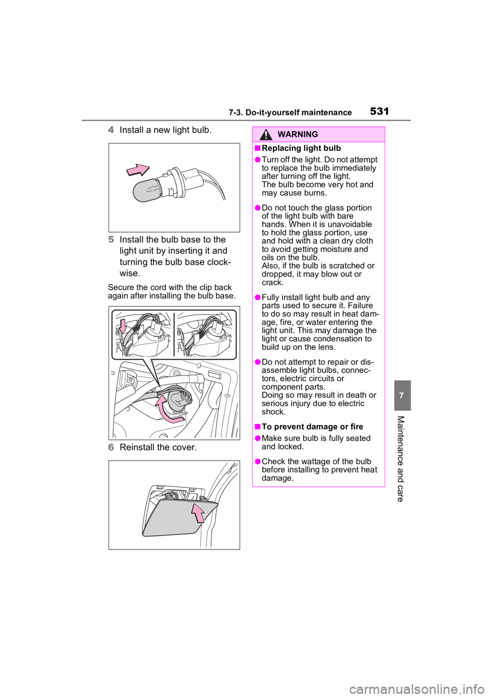
4Install a new light bulb.
5 Install the bulb base to the
light unit by inserting it and
turning the bulb base clock-
wise.
Secure the cord wit h the clip back
again after installing the bulb base.
6 Reinstall the cover.
WARNING
■Replacing light bulb
●Turn off the light. Do not attempt
to replace the bu lb immediately
after turning off the light.
The bulb become very hot and
may cause burns.
●Do not touch the glass portion
of the light bulb with bare
hands. When it is unavoidable
to hold the glass portion, use
and hold with a clean dry cloth
to avoid getting moisture and
oils on the bulb.
Also, if the bulb is scratched or
dropped, it may blow out or
crack.
●Fully install light bulb and any
parts used to secure it. Failure
to do so may result in heat dam-
age, fire, or water entering the
light unit. This may damage the
light or cause condensation to
build up on the lens.
●Do not attempt to repair or dis-
assemble light bulbs, connec-
tors, electric circuits or
component parts.
Doing so may result in death or
serious injury due to electric
shock.
■To prevent damage or fire
●Make sure bulb is fully seated
and locked.
●Check the wattage of the bulb
before installing to prevent heat
damage.