2023 TOYOTA RAV4 HYBRID replacement
[x] Cancel search: replacementPage 424 of 586
4226-3. Do-it-yourself maintenance
When replacing wheels, care
should be taken to ensure that
they are equivalent to those
removed in load capacity, diam-
eter, rim width and inset
*.
Replacement wheels are avail-
able at your Toyota dealer.
*: Conventionally referred to as off- set.
Toyota does not recommend
using the following:
Wheels of different sizes or
types
Used wheels
Bent wheels that have been
straightened
■When replacing wheels (vehi-
cles with tire p ressure warning
system)
The wheels of your vehicle are
equipped with tire pressure warning
valves and transmitters that allow
the tire pressure warning system to
provide advance warning in the
event of a loss in tire inflation pres-
sure. Whenever wheels are
replaced, tire pressure warning
valves and transmitters must be
installed. ( P.412, 423)
WARNING
■Proper inflation is critical to
save tire performance
Keep your tires properly inflated.
If the tires are not properly
inflated, the following conditions
may occur which could lead to an
accident resulting in death or seri-
ous injury:
●Excessive wear
●Uneven wear
●Poor handling
●Possibility of blowouts resulting
from overheated tires
●Air leaking from between tire
and wheel
●Wheel deformation and/or tire
damage
●Greater possibility of tire dam-
age while driving (due to road
hazards, expansion joints,
sharp edges in the road, etc.)
NOTICE
■When inspecting and adjust-
ing tire inflation pressure
Be sure to put the tire valve caps
back on.
If a valve cap is not installed, dirt
or moisture may get into the valve
and cause an air leak, resulting in
decreased tire inflation pressure.
Wheels
If a wheel is bent, cracked or
heavily corroded, it should
be replaced. Otherwise, the
tire may separate from the
wheel or cause a loss of
handling control.
Wheel selection
Page 427 of 586
4256-3. Do-it-yourself maintenance
6
Maintenance and care
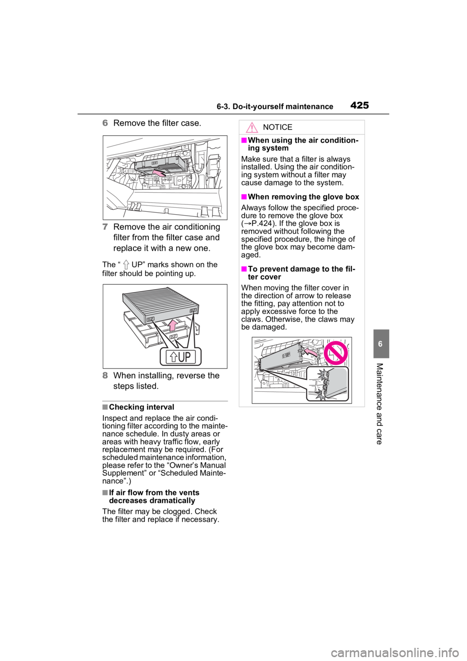
6Remove the filter case.
7 Remove the air conditioning
filter from the filter case and
replace it with a new one.
The “ UP” marks shown on the
filter should be pointing up.
8When installing, reverse the
steps listed.
■Checking interval
Inspect and replace the air condi-
tioning filter according to the mainte-
nance schedule. In dusty areas or
areas with heavy traffic flow, early
replacement may be required. (For
scheduled maintenance information,
please refer to the “Owner’s Manual
Supplement” or “Scheduled Mainte-
nance”.)
■If air flow from the vents
decreases dramatically
The filter may be clogged. Check
the filter and replace if necessary.
NOTICE
■When using the air condition-
ing system
Make sure that a filter is always
installed. Using the air condition-
ing system without a filter may
cause damage to the system.
■When removing the glove box
Always follow the specified proce-
dure to remove the glove box
( P.424). If the glove box is
removed without following the
specified procedure, the hinge of
the glove box may become dam-
aged.
■To prevent damage to the fil-
ter cover
When moving the filter cover in
the direction of arrow to release
the fitting, pay attention not to
apply excessive force to the
claws. Otherwise, the claws may
be damaged.
Page 432 of 586
4306-3. Do-it-yourself maintenance
driver with a rag.
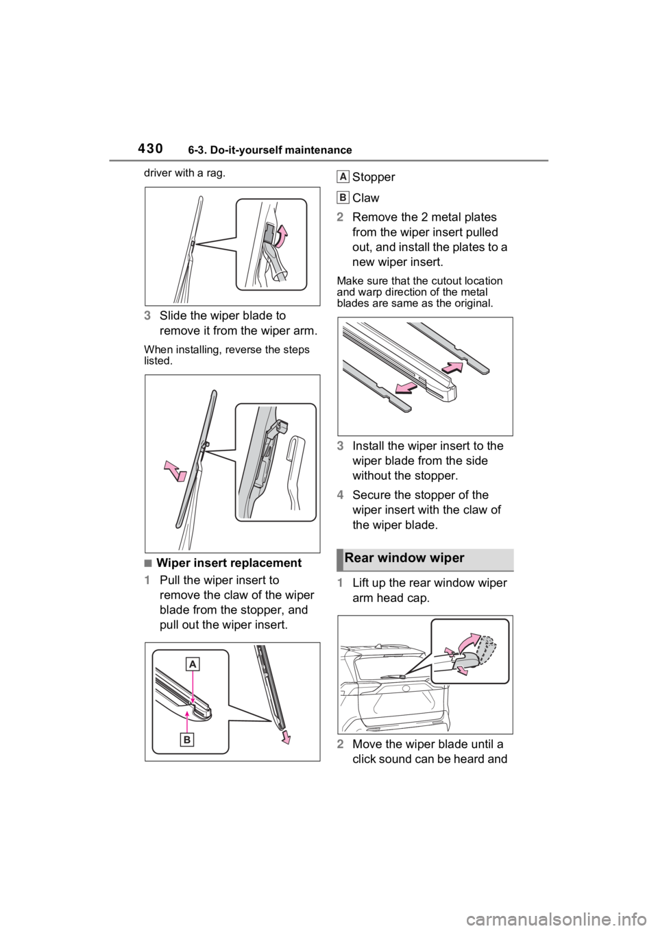
3Slide the wiper blade to
remove it from the wiper arm.
When installing, rev erse the steps
listed.
■Wiper insert replacement
1 Pull the wiper insert to
remove the claw of the wiper
blade from the stopper, and
pull out the wiper insert. Stopper
Claw
2 Remove the 2 metal plates
from the wiper insert pulled
out, and install the plates to a
new wiper insert.
Make sure that the cutout location
and warp direction of the metal
blades are same as the original.
3Install the wiper insert to the
wiper blade from the side
without the stopper.
4 Secure the stopper of the
wiper insert with the claw of
the wiper blade.
1 Lift up the rear window wiper
arm head cap.
2 Move the wiper blade until a
click sound can be heard and
Rear window wiper
A
B
Page 439 of 586

4376-3. Do-it-yourself maintenance
6
Maintenance and care
3Remove the fuse.
Only type A fuse can be removed
using the pullout tool.
4Check if the fuse is blown.
Replace the blown fuse with a new
fuse of an appropriate amperage
rating. The amperage rating can be
found on the fuse box lid.
Type A
Normal fuse
Blown fuse
Type BNormal fuse
Blown fuse
Type CNormal fuse
Blown fuse
■After a fuse is replaced
●When installing the lid, make sure
that the tab is ins talled securely.
●If the lights do not turn on even
after the fuse has been replaced,
a bulb may need replacement.
( P.439)
●If the replaced fuse blows again,
have the vehicle inspected by
your Toyota dealer.
■If there is an ove rload in a cir-
cuit
The fuses are designed to blow,
protecting the wiring harness from
damage.A
B
A
B
A
B
Page 441 of 586
4396-3. Do-it-yourself maintenance
6
Maintenance and care
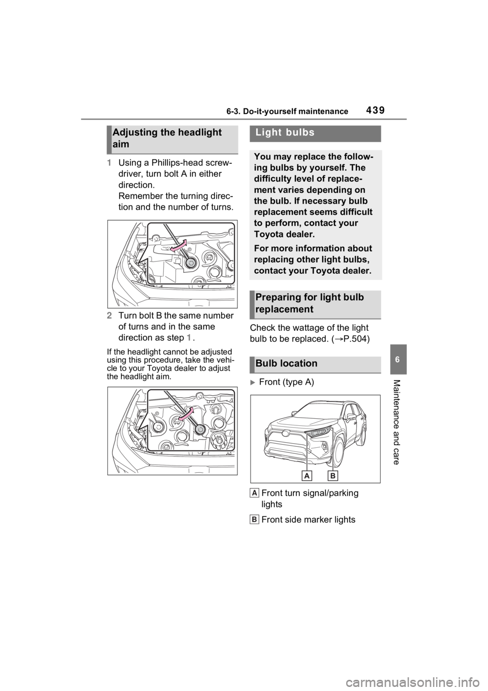
1Using a Phillips-head screw-
driver, turn bolt A in either
direction.
Remember the turning direc-
tion and the number of turns.
2 Turn bolt B the same number
of turns and in the same
direction as step 1.
If the headlight cannot be adjusted
using this procedure, take the vehi-
cle to your Toyota dealer to adjust
the headlight aim.
Check the wattage of the light
bulb to be replaced. ( P.504)
Front (type A)
Front turn signal/parking
lights
Front side marker lights
Adjusting the headlight
aimLight bulbs
You may replace the follow-
ing bulbs by yourself. The
difficulty level of replace-
ment varies depending on
the bulb. If necessary bulb
replacement seems difficult
to perform, contact your
Toyota dealer.
For more information about
replacing other light bulbs,
contact your Toyota dealer.
Preparing for light bulb
replacement
Bulb location
A
B
Page 468 of 586
4667-2. Steps to take in an emergency
■Warning messages
The warning messages explained
below may differ from the actual
messages according to operation
conditions and vehicle specifica-
tions.
■If a message about an operation
is shown
●If a message about an operation
of the accelerator pedal or brake
pedal is shown
●A warning message about an
operation of the brake pedal may
be shown while the driving assist
WARNING
Your vehicle has also been
equipped with a TPMS (tire pres-
sure warning system) malfunc-
tion indicator to indicate when the
system is not opera ting properly.
The TPMS (tire pressure warning
system) malfunction indicator is
combined with the low tire pres-
sure telltale (tire pressure warning
light). When the system detects a
malfunction, the telltale will flash
for approximately one minute and
then remain continuously illumi-
nated. This sequence will con-
tinue upon subsequent vehicle
start-ups as long as the malfunc-
tion exists. When the malfunction
indicator is illuminated, the sys-
tem may not be able to detect or
signal low tire pressure as
intended.
TPMS (tire pressure warning sys-
tem) malfunctions may occur for a
variety of reasons, including the
installation of replacement or
alternate tires or wheels on the
vehicle that prevent the TPMS
(tire pressure warning system)
from functioning properly. Always
check the TPMS ( tire pressure
warning system) malfunction tell-
tale after replacing one or more
tires or wheels on your vehicle to
ensure that the r eplacement or
alternate tires and wheels allow
the TPMS (tire pressure warning
system) to continue to function
properly.
NOTICE
■To ensure the tire pressure
warning system operates
properly (vehicles with tire
pressure warning system)
Do not install tires with different
specifications or makers, as the
tire pressure warning system may
not operate properly.
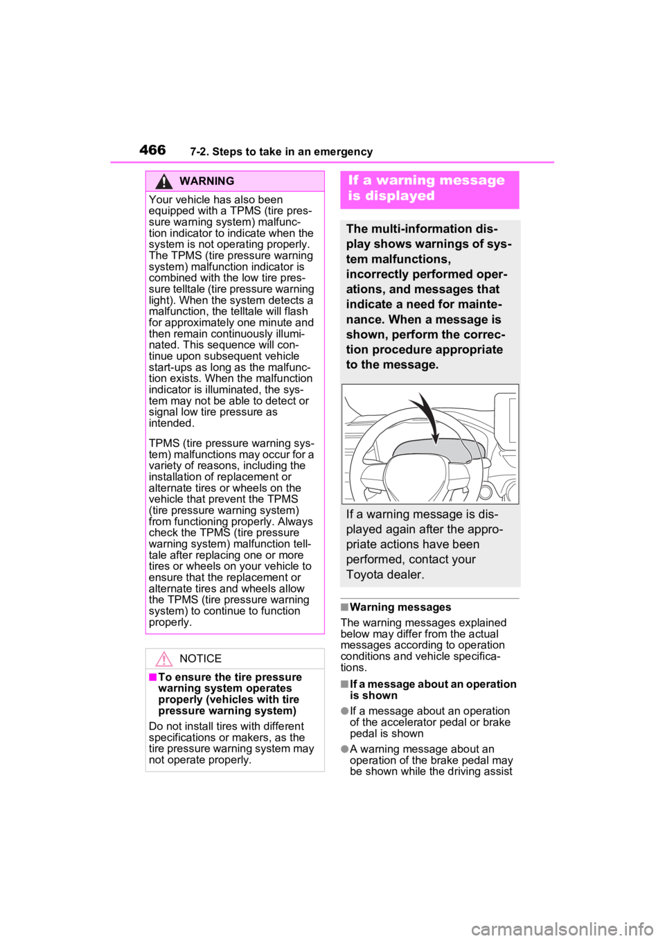
If a warning message
is displayed
The multi-information dis-
play shows warnings of sys-
tem malfunctions,
incorrectly performed oper-
ations, and messages that
indicate a need for mainte-
nance. When a message is
shown, perform the correc-
tion procedure appropriate
to the message.
If a warning message is dis-
played again after the appro-
priate actions have been
performed, contact your
Toyota dealer.
Page 490 of 586
4887-2. Steps to take in an emergency
Use a battery that the case size is
same as the previous one (LN1), 20
hours rate capacity (20HR) is equiv-
alent (45Ah) or greater, and perfor-
mance rating (CCA) is equivalent
(286A) or greater.
Type C:
Use a battery that the case size is
same as the previous one (LN2), 20
hours rate capacity (20HR) is equiv-
alent (55Ah) or greater, and perfor-
mance rating (CCA) is equivalent
(345A) or greater.
• If the sizes differ, the 12-volt bat-
tery cannot be properly secured.
• If the 20 hour rate capacity is low,
even if the time period where the
vehicle is not used is a short time,
the 12-volt battery may discharge
and hybrid system may not be
able to start.
●Use a ventilation t ype calcium bat-
tery
●Use a 12-volt battery with a han-
dle. If a 12-volt b attery without a
handle is used, removal is more
difficult.
●When removing the 12-volt bat-
tery: P.408
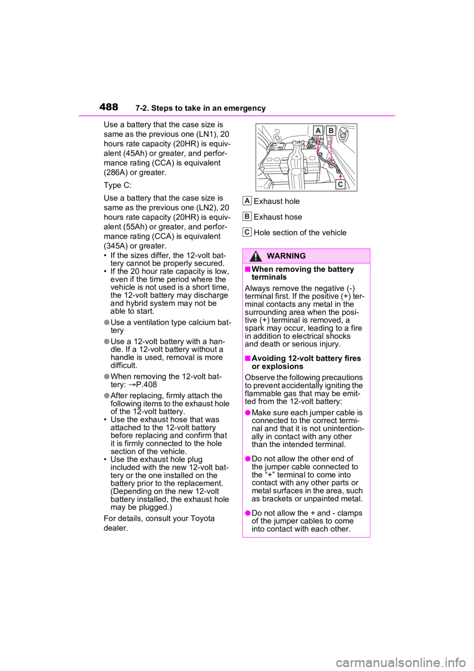
●After replacing, firmly attach the
following items to the exhaust hole
of the 12-volt battery.
• Use the exhaust hose that was attached to the 12-volt battery
before replacing an d confirm that
it is firmly connected to the hole
section of t he vehicle.
• Use the exhaust hole plug included with the new 12-volt bat-
tery or the one installed on the
battery prior to t he replacement.
(Depending on the new 12-volt
battery installed, the exhaust hole
may be plugged.)
For details, consult your Toyota
dealer. Exhaust hole
Exhaust hose
Hole section of the vehicle
WARNING
■When removing the battery
terminals
Always remove the negative (-)
terminal first. If the positive (+) ter-
minal contacts any metal in the
surrounding area when the posi-
tive (+) terminal is removed, a
spark may occur, leading to a fire
in addition to ele ctrical shocks
and death or serious injury.
■Avoiding 12-volt battery fires
or explosions
Observe the following precautions
to prevent accidentally igniting the
flammable gas that may be emit-
ted from the 12-volt battery:
●Make sure each jumper cable is
connected to the correct termi-
nal and that it is not unintention-
ally in contact with any other
than the intended terminal.
●Do not allow the other end of
the jumper cable connected to
the “+” terminal to come into
contact with any other parts or
metal surfaces in the area, such
as brackets or unpainted metal.
●Do not allow the + and - clamps
of the jumper cables to come
into contact with each other.
A
B
C
Page 502 of 586

5008-1. Specifications
*: The coolant capacity is the quantity of reference.
If replacement is necessary, contact y our Toyota dealer.
Cooling system
Capacity*Gasoline engine6.4 qt. (6.1 L, 5.4 Imp. qt.)
Power control unit1.7 qt. (1.6 L, 1.4 Imp. qt.)
Coolant type
Use either of the following:
“Toyota Super Long Life Coolant”
Similar high-quality ethylene gly-
col-based non-silicate, non-amine,
non-nitrite, and non-borate cool-
ant with long-life hybrid organic
acid technology
Do not use plain water alone.
Ignition system (spark plug)
MakeDENSO FC16HR-Q8
Gap0.031 in. (0.8 mm)
NOTICE
■Iridium-tipped spark plugs
Use only iridium-tipped spark plugs. Do not adjust the spark pl ug gap.
Electrical system (12-volt Battery)
Specific voltage reading at
68°F (20°C):
12.0 V or higher
(Turn the power switch to OFF and turn on
the high beam headlights for 30 seconds.)
If the voltage is lower than the standard
value, charge the 12-volt battery.
Charging ratesQuick charge15 A max.
Slow charge5 A max.