Page 253 of 552

2534-5. Using the driving support systems
4
Driving
When the turn signal lever is operated and your vehicle moves to an over-
taking lane while driving at 50 mph (80 km/h) or more, the vehi cle will accel-
erate to help to overt ake a passing vehicle.
The system’s identification of what is an overtaking lane may be determined
solely based on the location of the steering wheel in the vehicle (left side
driver position versus right side driver position.) If the vehi cle is driven to a
region where the overtaking lane is on a different side from wh ere the vehi-
cle is normally driven, the vehicle may accelerate when the tur n signal lever
is operated in the opposite direction to the overtaking lane (e .g., if the driver
normally operates the vehicle in a region where the overtaking lane is to the
right but then drives to a region where the overtaking lane is to the left, the
vehicle may accelerate when the right turn signal is activated).
Example of acceleration
When there are no longer any preceding vehicles driving slower
than the set speed
The system accelerates until the set speed is reached. The system then
returns to constan t speed cruising.
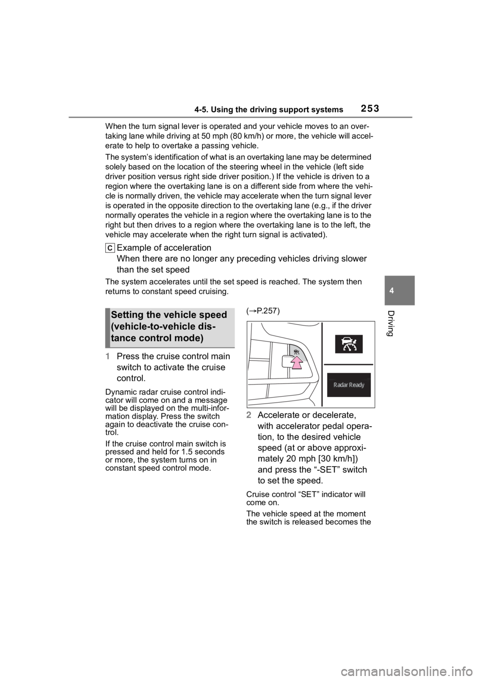
1Press the cruise control main
switch to activate the cruise
control.
Dynamic radar cruise control indi-
cator will come on and a message
will be displayed on the multi-infor-
mation display. Press the switch
again to deactivate the cruise con-
trol.
If the cruise cont rol main switch is
pressed and held for 1.5 seconds
or more, the syste m turns on in
constant speed control mode. (
P.257)
2 Accelerate or decelerate,
with accelerator pedal opera-
tion, to the desired vehicle
speed (at or above approxi-
mately 20 mph [30 km/h])
and press the “-SET” switch
to set the speed.
Cruise control “SET” indicator will
come on.
The vehicle speed at the moment
the switch is released becomes the
Setting the vehicle speed
(vehicle-to-vehicle dis-
tance control mode)
Page 270 of 552

2704-5. Using the driving support systems
*: If equipped
Meter control switches
Turning the Blind Spot Monitor
on/off.
Outside rear view mirror indi-
cators
When driving:
When a vehicle is detected in a
blind spot of the outside rear view
mirrors or approaching rapidly from
behind into a blind spot, the outside
rear view mirror indicator on the
detected side will illuminate. If the
turn signal lever is operated toward
the detected side, the outside rear
view mirror indicator flashes.
BSM OFF indicator
Illuminates when the Blind Spot
Monitor is disabled.
■Outside rear view mirror indica-
tor visibility
In strong sunlight, the outside rear
view mirror indicator may be difficult
to see.
■When “Blind Spot Monitor
Unavailable” is shown on the
multi-information display
Ice, snow, mud, etc., may be
attached to the rear bumper around
the sensors. ( P.271) The system
should return to normal operation
after removing the ice, snow, mud,
BSM (Blind Spot Moni-
tor)*
The Blind Spot Monitor is a
system that uses rear side
radar sensors installed on
the inner side of the rear
bumper on the left and right
side to assist the driver in
confirming safety when
changing lanes.
WARNING
■Cautions regarding the use of
the system
The driver is solely responsible for
safe driving. Always drive safely,
taking care to o bserve your sur-
roundings.
The Blind Spot Monitor is a sup-
plementary function which alerts
the driver that a v ehicle is in a
blind spot of the outside rear view
mirrors or is approaching rapidly
from behind into a blind spot. Do
not overly rely on the Blind Spot
Monitor. As the function cannot
judge if it is safe to change lanes,
over reliance could lead to an
accident resulting in death or seri-
ous injury.
As the system may not function
correctly under certain condi-
tions, the driver’s own visual con-
firmation of safety is necessary.
System components
Page 415 of 552
4156-3. Do-it-yourself maintenance
6
Maintenance and care
Check the wattage of the light
bulb to be replaced. (P.481)
P. 4 9 9
Front (type A)
Front turn signal lights/park- ing lights
Front side marker lights
Front (type B)
Front turn signal lights
Front side marker lights
Front (type C)
Front turn signal lights/park-
ing lights
Front side marker lights
RearRear turn signal lights
Light bulbs
You may replace the follow-
ing bulbs by yourself. The
difficulty level of replace-
ment varies depending on
the bulb. If necessary bulb
replacement seems difficult
to perform, contact your
Toyota dealer.
For more information about
replacing other light bulbs,
contact your Toyota dealer.
Preparing for light bulb
replacement
Turning off the power
back door main switch (if
equipped)
Bulb locations
Page 416 of 552

4166-3. Do-it-yourself maintenance
Back-up lights
License plate lights
■Lights that need to be
replaced by your Toyota
dealer
Headlight low beams
Headlight high beams
Daytime running lights (types
A and C)
Daytime running lights/park-
ing lights (type B)
Front fog lights (if equipped)
Side turn signal lights
Tail lights/stop lights
Rear side marker lights
Tail lights
High mounted stoplight
Outer foot lights (if equipped)
■LED lights
The lights other than the following
lights each consist of a number of
LEDs. If any of the LEDs burn out,
take your vehicle to your Toyota
dealer to have the light replaced.
●Front turn signal lights/parking
lights (types A and C)
●Front turn signal lights (type B)
●Front side marker lights
●Rear turn signal lights
●Back-up lights
●License plate lights
■Condensation build-up on the
inside of the lens
Temporary condensation build-up
on the inside of the light lens does
not indicate a malfunction. Contact
your Toyota dealer for more informa- tion in the following situations:
●Large drops of water have built up
on the inside of the lens.
●Water has built up
inside the light.
■When replacing light bulbs
P.413
■Front turn signal
lights/parking lights (types
A and C) and front turn sig-
nal lights (type B)
1 Turn the bulb base counter-
clockwise and remove it.
2 Remove the light bulb.
3 Install a new light bulb, and
then install the bulb base to
the light unit by inserting it
and turning the bulb base
clockwise.
After installing the bulb base, wig-
gle it lightly to make sure it is
Replacing light bulbs
Page 417 of 552
4176-3. Do-it-yourself maintenance
6
Maintenance and care
securely installed and turn the lights
and turn signal lights on to visually
check that there is no light leaking
from between the bulb base and
light unit.
■Front side marker lights
1 Turn the bulb base counter-
clockwise and remove it.
2 Remove the light bulb.
3 Install a new light bulb, and
then install the bulb base to
the light unit by inserting it
and turning the bulb base
clockwise.
After installing th e bulb base, wig- gle it lightly to make sure it is
securely installed a
nd turn the lights
on to visually check that there is no
light leaking from between the bulb
base and light unit.
■Rear turn signal lights
1 Open the back door and
using a flathead screwdriver,
remove the cover.
To prevent damage to the vehicle,
wrap the tip of th e flathead screw-
driver with tape, etc.
2 Remove the securing 2
screws and light unit.
Remove the light u nit by pulling it
straight back from the rear of the
Page 418 of 552
4186-3. Do-it-yourself maintenance
vehicle.
3Disconnect the wire harness.
4 Turn the bulb base counter-
clockwise and remove it.
5 Remove the light bulb. 6
Install a new light bulb, and
then install the bulb base to
the light unit by inserting it
and turning it clockwise.
After installing the bulb base, wig-
gle it lightly to make sure it is
securely installed and turn on the
turn signal lights to visually check
that there is no light leaking from
between the bulb base and light
unit.
7Install the light unit.
Align the 2 guides and push the
light unit toward the front of the
vehicle to install it.
Page 424 of 552

4247-1. Essential information
7-1.Essential information
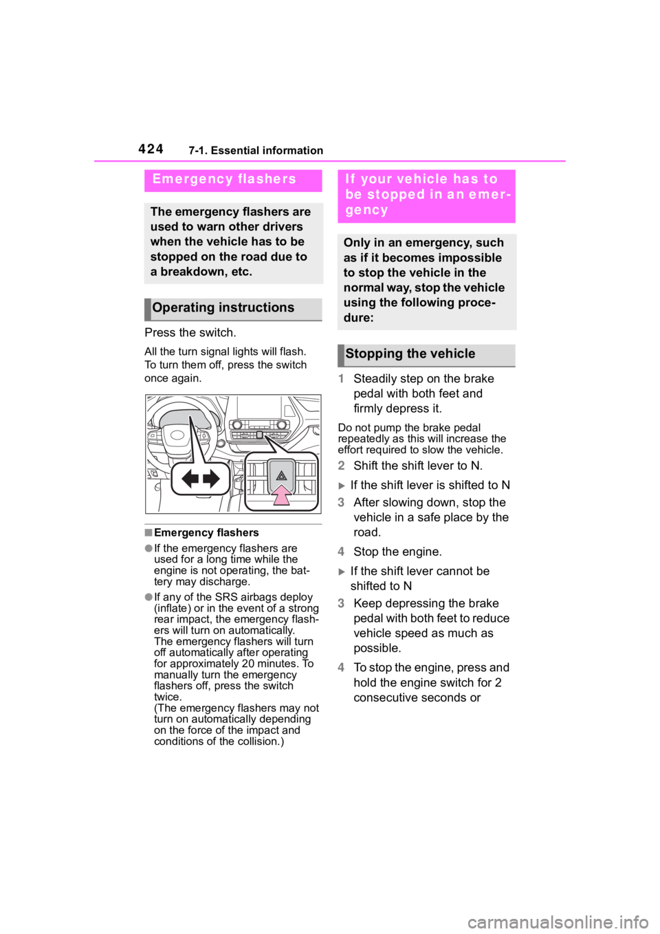
Press the switch.
All the turn signal lights will flash.
To turn them off, press the switch
once again.
■Emergency flashers
●If the emergency flashers are
used for a long time while the
engine is not operating, the bat-
tery may discharge.
●If any of the SRS airbags deploy
(inflate) or in the event of a strong
rear impact, the emergency flash-
ers will turn on automatically.
The emergency flashers will turn
off automatically after operating
for approximately 20 minutes. To
manually turn t he emergency
flashers off, press the switch
twice.
(The emergency flashers may not
turn on automatically depending
on the force of the impact and
conditions of the collision.)
1 Steadily step on the brake
pedal with both feet and
firmly depress it.
Do not pump the brake pedal
repeatedly as this will increase the
effort required to slow the vehicle.
2Shift the shift lever to N.
If the shift lever is shifted to N
3 After slowing down, stop the
vehicle in a safe place by the
road.
4 Stop the engine.
If the shift lever cannot be
shifted to N
3 Keep depressing the brake
pedal with both feet to reduce
vehicle speed as much as
possible.
4 To stop the engine, press and
hold the engine switch for 2
consecutive seconds or
Emergency flashers
The emergency flashers are
used to warn other drivers
when the vehicle has to be
stopped on the road due to
a breakdown, etc.
Operating instructions
If your vehicle has to
be stopped in an emer-
gency
Only in an emergency, such
as if it becomes impossible
to stop the vehicle in the
normal way, stop the vehicle
using the following proce-
dure:
Stopping the vehicle
Page 481 of 552
4818-1. Specifications
8
Vehicle specifications
A: Wedge base bulbs (amber)
B: Wedge base bulbs (clear)
C: Double end bulbs (clear)
Wheel size18 8 J
Wheel nut torque76 ft•lbf (103 N•m, 10.5 kgf•m)
Light bulbs
Light bulbsBulb No.WTy p e
Exterior
Front side marker lights5B
Front turn signal lights7444NA28A
Rear turn signal lights21A
Back-up lights16B
License plate lights5B
Parking lights7444NA8A
Interior
Door courtesy lights1685B
Vanity lights8B
Rear personal light8B
Rear interior light8C