Page 73 of 552
73
2
2
Vehicle status information and indicators
Vehicle status informationand indicators
.2-1. Instrument cluster
Warning lights and indica-tors ............................... 74
Gauges and meters (7-inch display) ......................... 79
Gauges and meters (12.3-inch display) ........ 82
Multi-information display (7-inch display) ............. 87
Multi-information display (12.3-inch display) ........ 96
Head-up display .......... 103
Fuel consumption informa- tion ............................ 108
Page 74 of 552
742-1. Instrument cluster
2-1.Instrument cluster
For the purpose of explanation, the following illustrations display all
warning lights and indicators illuminated.
7-inch display
The units used on the meters and some indicators may differ
depending on the target region.
War ning lights and indicators
The warning lights and indicators on the instrument cluster,
center panel and outside rear view mirrors inform the driver of
the status of the vehicle’s various systems.
Warning lights and indicators displayed on the instru-
ment cluster
Page 75 of 552

752-1. Instrument cluster
2
Vehicle status information and indicators
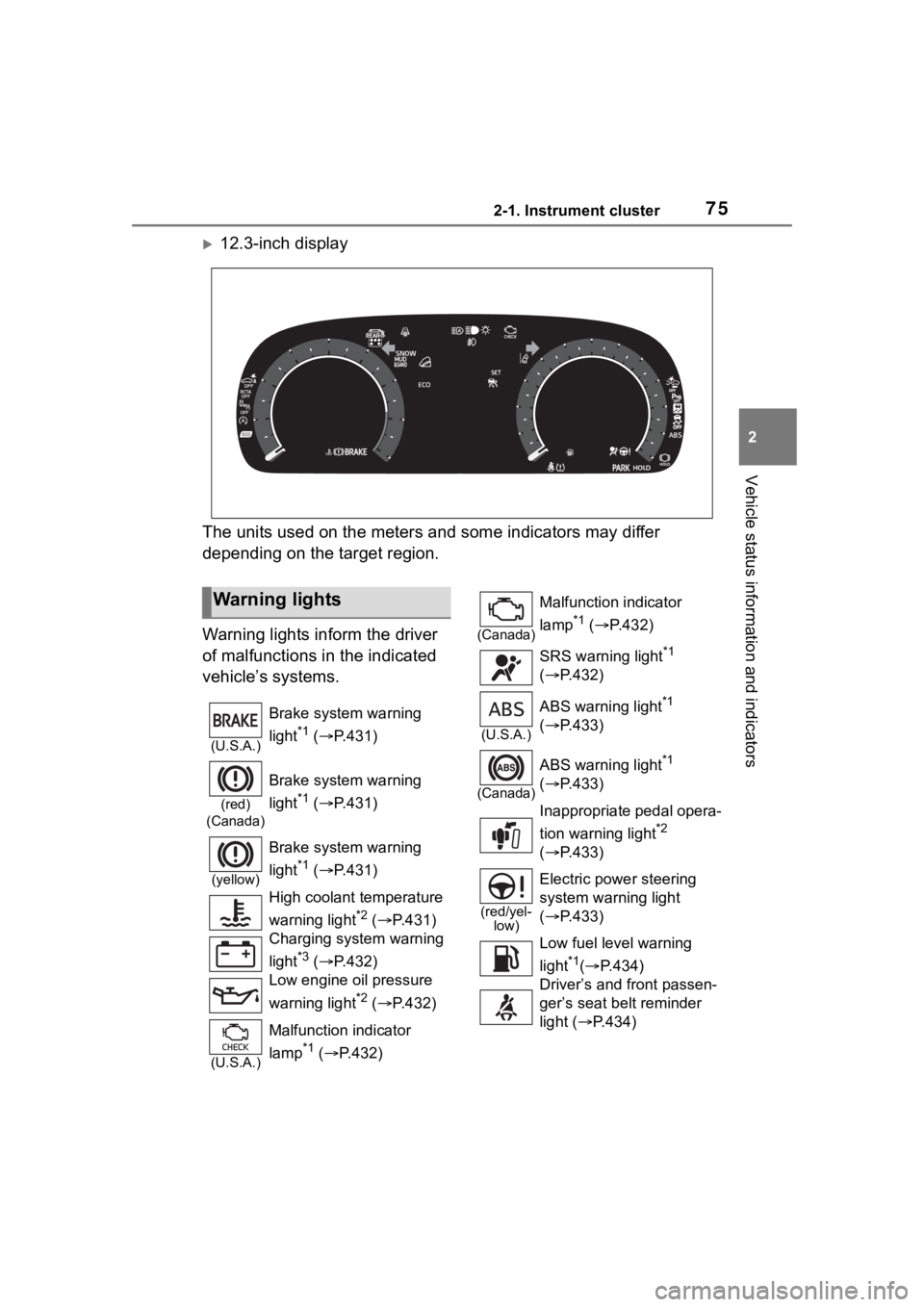
12.3-inch display
The units used on the meters and some indicators may differ
depending on the target region.
Warning lights inform the driver
of malfunctions in the indicated
vehicle’s systems.
Warning lights
(U.S.A.)
Brake system warning
light
*1 ( P.431)
(red)
(Canada)
Brake system warning
light
*1 ( P.431)
(yellow)
Brake system warning
light
*1 ( P.431)
High coolant temperature
warning light
*2 ( P.431)
Charging system warning
light
*3 ( P.432)
Low engine oil pressure
warning light
*2 ( P.432)
(U.S.A.)
Malfunction indicator
lamp
*1 ( P.432)
(Canada)
Malfunction indicator
lamp
*1 ( P.432)
SRS warning light
*1
( P.432)
(U.S.A.)
ABS warning light*1
( P.433)
(Canada)
ABS warning light*1
( P.433)
Inappropriate pedal opera-
tion warning light
*2
( P.433)
(red/yel-
low)
Electric power steering
system warning light
( P.433)
Low fuel leve l warning
light
*1( P.434)
Driver’s and front passen-
ger’s seat belt reminder
light ( P.434)
Page 76 of 552

762-1. Instrument cluster
*1: These lights turn on when the engine switch is turned to ON to
indicate that a system check is
being performed. They will turn
off after the engine is started, or
after a few seconds. There may
be a malfunction in a system if a
light does not come on, or turn
off. Have the vehicle inspected
by your Toyota dealer.
*2: This light illuminates on the
multi-information display.
*3: 7-inch display only: These lights turn on when the engine switch
is turned to ON to i ndicate that a
system check is being per-
formed. They will turn off after
the engine is started, or after a
few seconds. There may be a
malfunction in a system if a light
does not come on, or turn off.
Have the vehicle inspected by
your Toyota dealer.
12.3-inch display only: This light
illuminates on the multi-informa-
tion display.
The indicators inform the driver
of the operating state of the
vehicle’s various systems.
Rear passengers’ seat
belt reminder light (7-inch
display)
*2 ( P.435)
Rear passengers’ seat
belt reminder light
(12.3-inch display)
*2
( P.435)
Tire pressure warning
light
*1 ( P.435)
(orange)
LTA indicator ( P.436)
(flashes)
Stop & Start cancel indica-
tor
*1 (if equipped)
( P.436)
(flashes)
Intuitive parking assist
OFF indicator
*1 (if
equipped) ( P.436)
“RCTA OFF” indicator (if
equipped)
*1 ( P.436)
(flashes)
PKSB OFF indicator*1 (if
equipped) ( P.437)
(flashes or
illumi-
nates)PCS warning light*1
( P.437)
Slip indicator
*1 ( P.438)
(flashes)
(U.S.A.)
Parking brake indicator*1
( P.438)
(flashes)
(Canada)
Parking brake indicator*1
( P.438)
(flashes)
Brake hold operated indi-
cator
*1 ( P.438)
WARNING
■If a safety system warning
light does not come on
Should a safety system light such
as the ABS and SRS warning
lights not come on when you start
the engine, this could mean that
these systems are not available to
help protect you in an accident,
which could result in death or seri-
ous injury. Have the vehicle
inspected by you r Toyota dealer
immediately if this occurs.
Indicators
Page 81 of 552

812-1. Instrument cluster
2
Vehicle status information and indicators
necessary.
■Changing the display
Each time the “ODO TRIP”
switch is pressed, the displayed
item will be changed. When the
trip meter is displayed, pressing
and holding the switch will reset
the trip meter.
■Pop-up display
In some situations the following
will be temporarily displayed:
Distance until next engine oil
change
Displays the distan ce until the next
engine oil change. This display will
be displayed in the following situa-
tions:
When the engine switch is
turned to ON.
When a warning message
indicating that oil mainte-
nance should be performed
soon or is required is dis-
played.
The brightness of the instrument
panel lights can be adjusted.
This image is for e xample only, and
may differ from the actual vehicle.
1 Darker
2 Brighter
■Brightness of the meters (day
mode and night mode)
The brightness of the meters is
changed between day mode and
night mode.
●Day mode: When the surrounding
area is bright
●Night mode: When the surround-
ing area is dark
The clocks can be adjusted on
the audio system screen.
Refer to “MULTIMEDIA
OWNER’S MANUAL”.
Changing the instrument
panel light brightness
Adjusting the clock
Page 86 of 552

862-1. Instrument cluster
has been driven since the meter
was last reset. Trip meters A and B
can be used to record and display
different distances independently.
Distance until next engine oil
change
Displays the distan ce the vehicle
can be driven until an oil change is
necessary.
■Pop-up display
In some situations the following
will be temporarily displayed:
Distance until next engine oil
change
Displays the distan ce until the next
engine oil change. This display will
be displayed in the following situa-
tions:
When the engine switch is
turned to ON.
When a warning message
indicating that oil mainte-
nance should be performed
soon or is required is dis-
played.
The brightness of the instrument
panel lights can be adjusted.
This image is for e xample only, and
may differ from the actual vehicle.
1 Darker
2 Brighter
■Brightness of the meters (day
mode and night mode)
The brightness of the meters is
changed between day mode and
night mode.
●Day mode: When the surrounding
area is bright
●Night mode: When the surround-
ing area is dark
■The clocks can be adjusted
on the audio system
screen.
Refer to “MULTIMEDIA
OWNER’S MANUAL”.
Changing the instrument
panel light brightness
Adjusting the clock
Page 95 of 552

952-1. Instrument cluster
2
Vehicle status information and indicators
■Vehicle functions and set-
tings that can be changed
P.494
■Background color of the indica-
tor/shift position display area
The background color of the indica-
tor/shift position display area is
changed according to the driving
mode as follows ( P.300):
●Eco drive mode: Blue
●Sport mode: Red
■Suspension of the settings dis-
play
●Some settings cannot be changed
while driving. When changing set-
tings, park the vehicle in a safe
place.
●If a warning message is displayed,
operation of the settings display
will be suspended.
■Pop-up displays
Depending on the pop-up display,
the currently disp layed item in the
message display area may be tem-
porarily not displayed. The item will
be displayed after the pop-up dis-
play is no longer displayed.
Select to display warning mes-
sages and measures to be
taken if a malfunction is
detected. ( P.442)
Displays suggestions to the
driver in the following situations.
To select a response to a dis-
played suggestion, use the
meter control switches.
■Suggestion to turn off the
headlights
If the headlights are left on for a
certain amount of time after the
engine switch has been turned
off, if the headlight switch is in
the “AUTO” position, a sugges-
tion message will be displayed
asking if you wish to turn the
headlights off.
To turn the headlights off, select
“Yes”.
If the driver's door is opened after
the engine switch is turned off, this
suggestion message will not be dis-
played.
WARNING
■Cautions during setting up
the display
As the engine needs to be run-
ning during setting up the display,
ensure that the vehicle is parked
in a place with adequate ventila-
tion. In a closed area such as a
garage, exhaust gases including
harmful carbon monoxide (CO)
may collect and enter the vehicle.
This may lead to death or a seri-
ous health hazard.
NOTICE
■During setting up the display
To prevent batte ry discharge,
ensure that the engine is running
while setting up the display fea-
tures.
Warning message display
()
Suggestion function
Page 149 of 552

1493-4. Adjusting the steering wheel and mirrors
3
Before driving
*: If equipped
The height of the rear view mir-
ror can be adjusted to suit your
driving posture.
Adjust the height of the rear
view mirror by moving it up and
down.
Manual anti-glare inside rear
view mirror
Reflected light from the head-
lights of vehicles behind can be
reduced by operating the lever.
Normal position
Anti-glare position
Auto anti-glare inside rear
view mirror
Responding to the level of
brightness of the headlights of
vehicles behind, the reflected
light is automatically reduced.
Turn the automatic anti-glare
function mode on/off
When the automatic anti-glare func-
tion is in ON mode, the indicator
illuminates. The func tion will set to
ON mode each time the engine
switch is turned to ON.
Pressing the button turns the func-
tion to OFF mode. (The indicator
also turns off.)
Inside rear view mir-
ror*
The rear view mirror’s posi-
tion can be adjusted to
enable sufficient confirma-
tion of the rear view.
Adjusting the height of
rear view mirror
WARNING
■Caution while driving
Do not adjust the position of the
mirror while driving.
Doing so may lead to mishandling
of the vehicle and cause an acci-
dent, resulting in death or serious
injury.
Anti-glare function