Page 373 of 468
3737-2. Steps to take in an emergency
7
When trouble arises
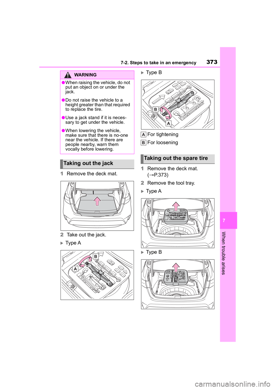
1Remove the deck mat.
2 Take out the jack.
Ty p e A
Type B
For tightening
For loosening
1 Remove the deck mat.
( P.373)
2 Remove the tool tray.
Type A
Type B
WARNING
●When raising the vehicle, do not
put an object on or under the
jack.
●Do not raise the vehicle to a
height greater than that required
to replace the tire.
●Use a jack stand if it is neces-
sary to get under the vehicle.
●When lowering the vehicle,
make sure that there is no-one
near the vehicle. If there are
people nearby, warn them
vocally before lowering.
Taking out the jack
Taking out the spare tire
Page 374 of 468
3747-2. Steps to take in an emergency
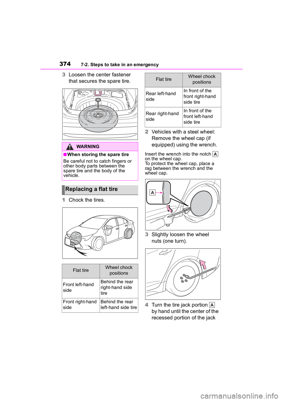
3Loosen the center fastener
that secures the spare tire.
1 Chock the tires. 2
Vehicles with a steel wheel:
Remove the wheel cap (if
equipped) using the wrench.
Insert the wrench i nto the notch
on the wheel cap.
To protect the whee l cap, place a
rag between the wrench and the
wheel cap.
3 Slightly loosen the wheel
nuts (one turn).
4 Turn the tire jack portion
by hand until the center of the
recessed portion of the jack
WARNING
■When storing the spare tire
Be careful not to catch fingers or
other body parts between the
spare tire and the body of the
vehicle.
Replacing a flat tire
Flat tireWheel chock positions
Front left-hand
sideBehind the rear
right-hand side
tire
Front right-hand
sideBehind the rear
left-hand side tire
Rear left-hand
sideIn front of the
front right-hand
side tire
Rear right-hand
sideIn front of the
front left-hand
side tire
Flat tireWheel chock positions
Page 376 of 468
3767-2. Steps to take in an emergency
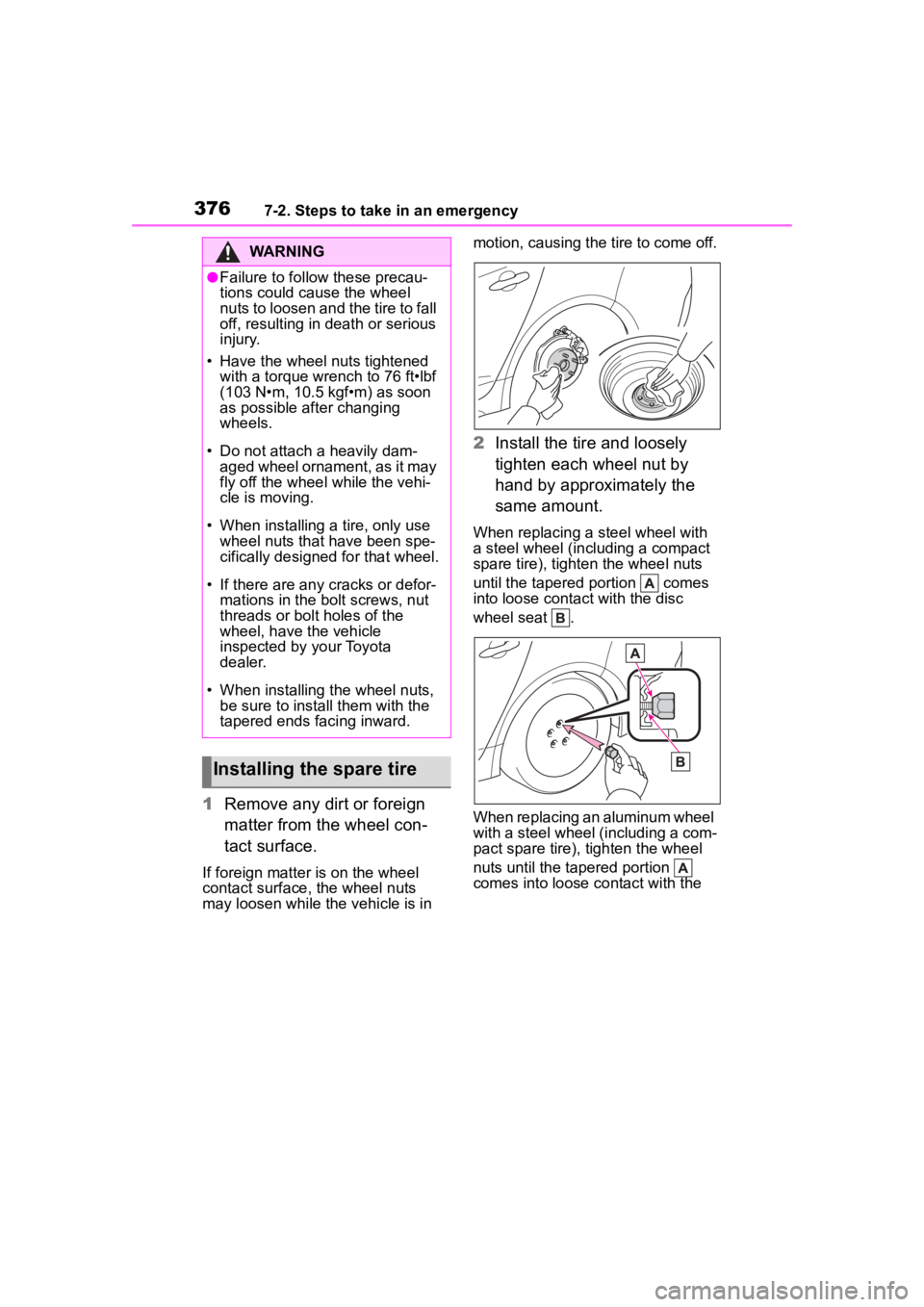
1Remove any dirt or foreign
matter from the wheel con-
tact surface.
If foreign matter is on the wheel
contact surface, the wheel nuts
may loosen while the vehicle is in motion, causing the tire to come off.
2
Install the tire and loosely
tighten each wheel nut by
hand by approximately the
same amount.
When replacing a steel wheel with
a steel wheel (including a compact
spare tire), tighten the wheel nuts
until the tapered portion comes
into loose contact with the disc
wheel seat .
When replacing an aluminum wheel
with a steel wheel (including a com-
pact spare tire), tighten the wheel
nuts until the tapered portion
comes into loose contact with the
WARNING
●Failure to follow these precau-
tions could cause the wheel
nuts to loosen and the tire to fall
off, resulting in death or serious
injury.
• Have the wheel nuts tightened with a torque wrench to 76 ft•lbf
(103 N•m, 10.5 kgf•m) as soon
as possible after changing
wheels.
• Do not attach a heavily dam- aged wheel ornament, as it may
fly off the whee l while the vehi-
cle is moving.
• When installing a tire, only use wheel nuts that have been spe-
cifically designed for that wheel.
• If there are any cracks or defor- mations in the bolt screws, nut
threads or bolt holes of the
wheel, have the vehicle
inspected by your Toyota
dealer.
• When installing the wheel nuts,
be sure to install them with the
tapered ends facing inward.
Installing the spare tire
Page 377 of 468
3777-2. Steps to take in an emergency
7
When trouble arises
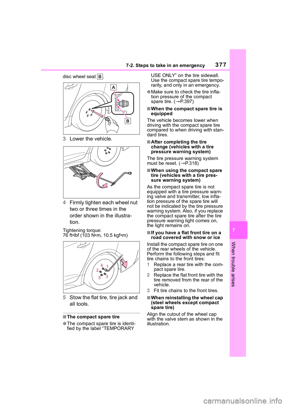
disc wheel seat .
3Lower the vehicle.
4 Firmly tighten each wheel nut
two or three times in the
order shown in the illustra-
tion.
Tightening torque:
76 ft•lbf (103 N•m, 10.5 kgf•m)
5Stow the flat tire, tire jack and
all tools.
■The compact spare tire
●The compact spare tire is identi-
fied by the label “TEMPORARY USE ONLY” on the tire sidewall.
Use the compact spare tire tempo-
rarily, and only in an emergency.
●Make sure to check the tire infla-
tion pressure of the compact
spare tire. (
P.397)
■When the compact spare tire is
equipped
The vehicle becomes lower when
driving with the compact spare tire
compared to when driving with stan-
dard tires.
■After completing the tire
change (vehicles with a tire
pressure warning system)
The tire pressure warning system
must be reset. ( P.318)
■When using the compact spare
tire (vehicles with a tire pres-
sure warning system)
As the compact spare tire is not
equipped with a tire pressure warn-
ing valve and transm itter, low infla-
tion pressure of t he spare tire will
not be indicated by the tire pressure
warning system. Also , if you replace
the compact spare ti re after the tire
pressure warning light comes on,
the light remains on.
■If you have a flat front tire on a
road covered with snow or ice
Install the compact spare tire on one
of the rear wheels of the vehicle.
Perform the following steps and fit
tire chains to the front tires:
1 Replace a rear tire with the com-
pact spare tire.
2 Replace the flat front tire with the
tire removed from the rear of the
vehicle.
3 Fit tire chains to the front tires.
■W h e n r e i n s t a l l i n g t h e w h e e l c a p
(steel wheels except compact
spare tire)
Align the cutout of the wheel cap
with the valve stem as shown in the
illustration.
Page 378 of 468
3787-2. Steps to take in an emergency
WARNING
■When using the compact
spare tire
●Remember that the compact
spare tire provided is specifi-
cally designed for use with your
vehicle. Do not use your com-
pact spare tire on another vehi-
cle.
●Do not use more than one com-
pact spare tires simultaneously.
●Replace the compact spare tire
with a standard tire as soon as
possible.
●Avoid sudden acceleration,
abrupt steering, sudden brak-
ing and shifting operations that
cause sudden engine braking.
■When the compact spare tire
is attached
The vehicle speed may not be
correctly detecte d, and the follow-
ing systems may not operate cor-
rectly:
• ABS & Brake assist
• VSC
• TRAC
• Automatic High Beam
• Dynamic radar cruise control
• EPS
• PCS (Pre-Collision System)
• LDA (Lane Departure Alert)
• LTA (Lane Tracing Assist)
• Tire pressure warning system (if equipped)
• BSM (if equipped)
• RCTA (if equipped)
• SEA (if equipped)
• Rear view monitor system
• Navigation system (if equipped)
■Speed limit when using the
compact spare tire
Do not drive at speeds in excess
of 50 mph (80 km /h) when a com-
pact spare tire is installed on the
vehicle.
The compact spare tire is not
designed for driving at high
speeds. Failure to observe this
precaution may lead to an acci-
dent causing death or serious
injury.
■After using the tools and jack
Before driving, ma ke sure all the
tools and jack are securely in
place in their storage location to
reduce the possibility of personal
injury during a collision or sudden
braking.
NOTICE
■Be careful when driving over
bumps with the compact
spare tire installed on the
vehicle.
The vehicle becomes lower when
driving with the compact spare tire
compared to when driving with
standard tires. Be careful when
driving over uneven road sur-
faces.
Page 379 of 468
3797-2. Steps to take in an emergency
7
When trouble arises
One of the following may be the
cause of the problem:
There may not be sufficient
fuel in the vehicle’s tank.
Refuel the vehicle.
The engine may be flooded.
Try to restart the engine again
following correct starting pro-
cedures. ( P.154, 155)
There may be a malfunction
in the engine immobilizer sys-
tem. ( P.77)
One of the following may be the
cause of the problem:
The battery may be dis-
charged. ( P.383)
NOTICE
■Driving with tire chains and
the compact spare tire
Do not fit tire chains to the com-
pact spare tire. Tire chains may
damage the vehicle body and
adversely affect driving perfor-
mance.
■When replacing the tires
(vehicles with a tire pressure
warning system)
When removing or fitting the
wheels, tires or the tire pressure
warning valve and transmitter,
contact your Toyota dealer as the
tire pressure warning valve and
transmitter may be damaged if not
handled correctly.
■To avoid damage to the tire
pressure warning valves and
transmitters (vehicles with a
tire pressure warning system)
When a tire is repaired with liquid
sealants, the tire pressure warn-
ing valve and transmitter may not
operate properly. If a liquid seal-
ant is used, contact your Toyota
dealer or other qualified service
shop as soon as possible. Make
sure to replace the tire pressure
warning valve and transmitter
when replacing the tire.
If the engine will not
star t
If the engine will not start
even though correct starting
procedures are being fol-
lowed ( P.154, 155), con-
sider each of the following
points:
The engine will not start
even though the starter
motor operates normally.
The starter motor turns
over slowly, the interior
lights and headlights are
dim, or the horn does not
sound or sounds at a low
volume.
Page 397 of 468
3978-1. Specifications
8
Vehicle specifications
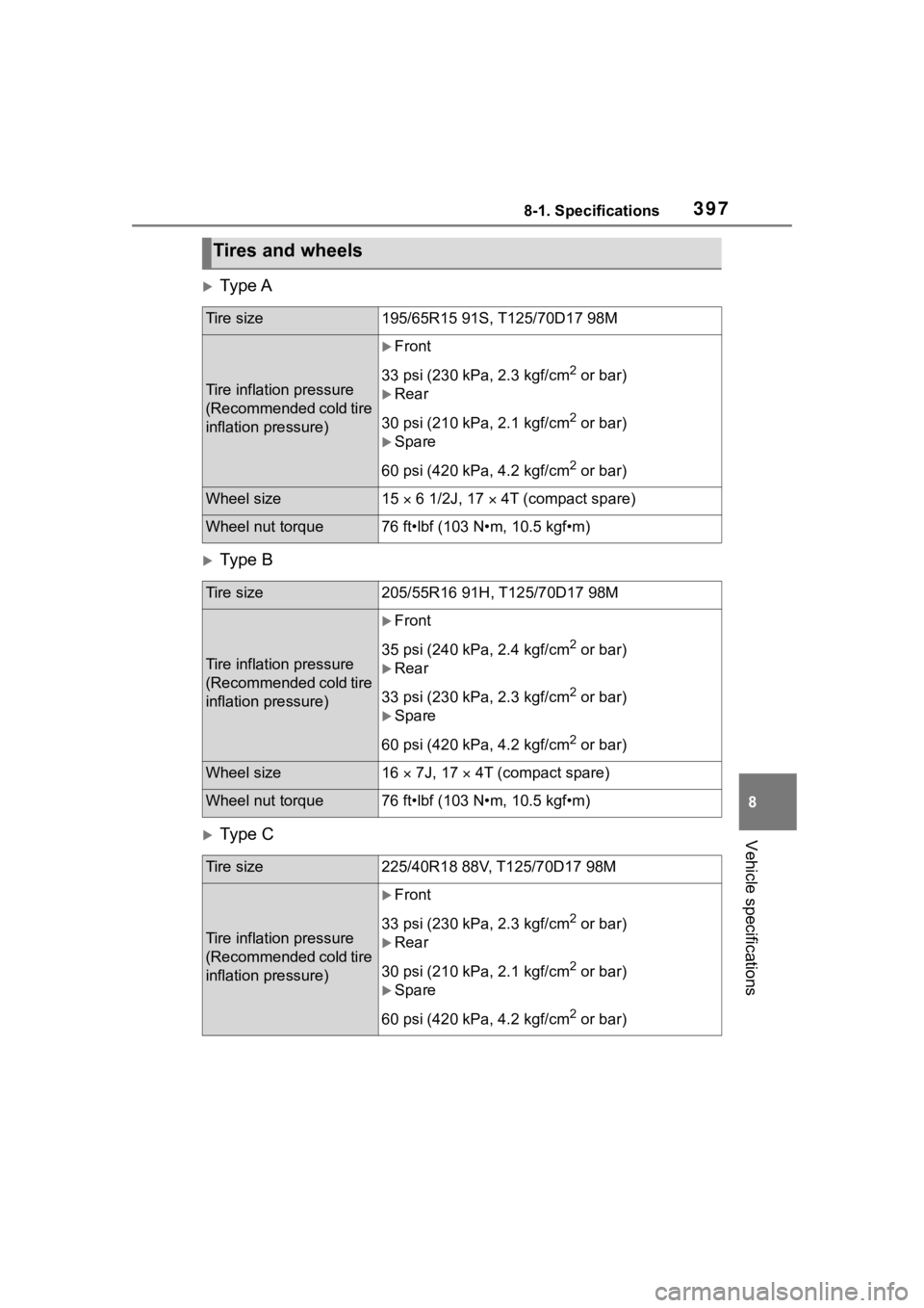
Ty p e A
Ty p e B
Ty p e C
Tires and wheels
Tire size195/65R15 91S, T125/70D17 98M
Tire inflation pressure
(Recommended cold tire
inflation pressure)
Front
33 psi (230 kPa, 2.3 kgf/cm
2 or bar)
Rear
30 psi (210 kPa, 2.1 kgf/cm
2 or bar)
Spare
60 psi (420 kPa, 4.2 kgf/cm
2 or bar)
Wheel size15 6 1/2J, 17 4T (compact spare)
Wheel nut torque76 ft•lbf (103 N•m, 10.5 kgf•m)
Tire size205/55R16 91H, T125/70D17 98M
Tire inflation pressure
(Recommended cold tire
inflation pressure)
Front
35 psi (240 kPa, 2.4 kgf/cm
2 or bar)
Rear
33 psi (230 kPa, 2.3 kgf/cm
2 or bar)
Spare
60 psi (420 kPa, 4.2 kgf/cm
2 or bar)
Wheel size16 7J, 17 4T (compact spare)
Wheel nut torque76 ft•lbf (103 N•m, 10.5 kgf•m)
Tire size225/40R18 88V, T125/70D17 98M
Tire inflation pressure
(Recommended cold tire
inflation pressure)
Front
33 psi (230 kPa, 2.3 kgf/cm
2 or bar)
Rear
30 psi (210 kPa, 2.1 kgf/cm
2 or bar)
Spare
60 psi (420 kPa, 4.2 kgf/cm
2 or bar)
Page 398 of 468
3988-1. Specifications
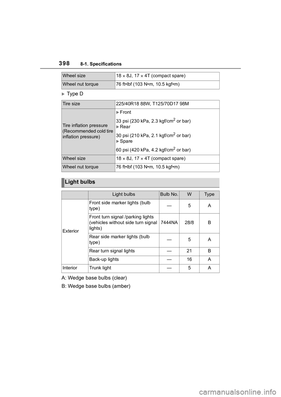
Ty p e D
A: Wedge base bulbs (clear)
B: Wedge base bulbs (amber)
Wheel size18 8J, 17 4T (compact spare)
Wheel nut torque76 ft•lbf (103 N•m, 10.5 kgf•m)
Tire size225/40R18 88W, T125/70D17 98M
Tire inflation pressure
(Recommended cold tire
inflation pressure)
Front
33 psi (230 kPa, 2.3 kgf/cm
2 or bar)
Rear
30 psi (210 kPa, 2.1 kgf/cm
2 or bar)
Spare
60 psi (420 kPa, 4.2 kgf/cm
2 or bar)
Wheel size18 8J, 17 4T (compact spare)
Wheel nut torque76 ft•lbf (103 N•m, 10.5 kgf•m)
Light bulbs
Light bulbsBulb No.WTy p e
Exterior
Front side marker lights (bulb
type)—5A
Front turn signal /parking lights
(vehicles without side turn signal
lights)
7444NA28/8B
Rear side marker lights (bulb
type)—5A
Rear turn signal lights—21B
Back-up lights—16A
InteriorTrunk light—5A