2023 TOYOTA COROLLA HYBRID fuel type
[x] Cancel search: fuel typePage 14 of 496

14Pictorial index
Fuel filler door .................................................................... P.196
Refueling method ............................................... .................. P.197
Fuel type/fuel tan k capacity ................................... .............. P.421
Tires.......................................................... ........................... P.325
Tire size/inflation pressure ................................... ................ P.426
Winter tires/tire chains ....................................... .................. P.273
Checking/rotation/tire pressur e warning system ..................P.325
Coping with flat tires......................................... ............ P.387, 398
Hood ........................................................... ......................... P.316
Opening ............................................................................... P.316
Engine oil ..................................................... ........................ P.422
Coping with overheating ...................................................... P.414
Headlights/daytime running lights .............................. ..... P.189
Turn signal lights/parking lights .............................. ......... P.189
Front side marker lights ....................................... ............. P.189
LED accent lights
*2............................................................ P.1 89
Stop lights/tail lights/rear side marker lights/turn signal lig hts
P. 1 8 9
License plate lights........................................... ................. P.189
Tail lights
*2............................................................... ........... P.189
Back-up lights
Shifting the shift position to R ............................... ............... P.180
Side turn signal lights
*2..................................................... P.182
*1: Vehicles with a smart key system
*2: If equipped
Light bulbs of the exterior lights for driving
(Replacing method: P.356, Watts: P.428)
Page 33 of 496

331-1. For safe use
1
For safety and security
Front impact sensors
Airbag sensor assembly
Your vehicle is equipped with ADVANCED AIRBAGS designed
based on the US motor vehicle safety standards (FMVSS208). The
airbag sensor assembly (ECU) cont rols airbag deployment based on
information obtained from the sensors etc. shown in the system
components diagram above. This in formation includes crash sever-
ity and occupant information. As the airbags deploy, a chemical
reaction in the inflators quickly fills the airbags with non-toxic gas to
help restrain the motion of the occupants.
■If the SRS airbags deploy
(inflate)
●Slight abrasions, burns, bruising
etc., may be sustained from SRS
airbags, due to the extremely high
speed deployment (inflation) by
hot gases.
●A loud noise and white powder will
be emitted.
●Parts of the airbag module (steer-
ing wheel hub, airbag cover and
inflator) as well as the front seats,
parts of the front and rear pillars,
and roof side rails, may be hot for
several minutes. T he airbag itself
may also be hot.
●The windshield may crack.
●The hybrid system will be stopped
and fuel supply to the engine will
be stopped. ( P. 8 6 )
●The brakes and st op lights will be
controlled automatically. ( P.267)
●The interior lights will turn on auto-
matically. ( P.287)
●The emergency flashers will turn
on automatically. ( P.362)
●For Safety Connect subscribers, if
any of the following situations
occur, the system is designed to
send an emergency call to the
response center, notifying them of
the vehicle’s location (without
needing to push the “SOS” button)
and an agent will attempt to speak with the occupants to ascertain
the level of emergency and assis-
tance required. If the occupants
are unable to communicate, the
agent automatically treats the call
as an emergency and helps to dis-
patch the necessary emergency
services. (
P. 7 2 )
• An SRS airbag is deployed.
• A seat belt pretensioner is acti-
vated.
• The vehicle is involved in a severe
rear-end collision.
■SRS airbag deployment condi-
tions (SRS front airbags)
●The SRS front airbags will deploy
in the event of an impact that
exceeds the set threshold level
(the level of forc e corresponding
to an approximately 12 - 18 mph
[20 - 30 km/h] frontal collision with
a fixed wall that does not move or
deform).
However, this threshold velocity will
be considerably higher in the follow-
ing situations:
• If the vehicle strikes an object, such as a parked vehicle or sign
pole, which can move or deform
on impact
• If the vehicle is involved in an underride collision, such as a colli-
sion in which the front of the vehi-
cle “underrides”, or goes under,
the bed of a truck
●Depending on the type of collision,
it is possible that only the seat belt
Page 80 of 496
801-4. Hybrid system
vehicle compared to the front.
*: This function can only be used in
the mainland U.S.A. It cannot be
used in other states and territo-
ries, including Alaska and Hawaii.
This system operates based on
the driving situation and traffic
information to enhance fuel
economy.
For details about Predictive effi-
cient drive, refer to the “MULTI-
MEDIA OWNER’S MANUAL”.
■Predictive deceleration sup-
port
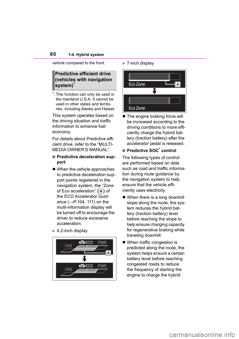
When the vehicle approaches
to predictive deceleration sup-
port points registered in the
navigation system, the “Zone
of Eco acceleration” ( ) of
the ECO Accelerator Guid-
ance (→P.104, 111) on the
multi-information display will
be turned off to encourage the
driver to reduce excessive
acceleration.
4.2-inch display
7-inch display
The engine braking force will
be increased according to the
driving conditions to more effi-
ciently charge the hybrid bat-
tery (traction battery) after the
accelerator pedal is released.
■Predictive SOC* control
The following types of control
are performed based on data
such as road and traffic informa-
tion during route guidance by
the navigation system to help
ensure that the vehicle effi-
ciently uses electricity.
When there is a long downhill
slope along the route, the sys-
tem reduces the hybrid bat-
tery (traction battery) level
before reaching the slope to
help ensure charging capacity
for regenerative braking while
traveling downhill.
When traffic congestion is
predicted along the route, the
system helps ensure a certain
battery level before reaching
congested roads to reduce
the frequency of starting the
engine to charge the hybrid
Predictive efficient drive
(vehicles with navigation
system)
*
Page 108 of 496

1082-1. Instrument cluster
• Average vehicle speed: Displays the average vehi cle speed since
the display was reset
*
*
: To reset, display the desired item
and press and hold the
meter control switch.
■AWD operation status dis-
play (AWD models)
The illustration used is intended as
an example, and may differ from the
image that is actually displayed on
the multi-information display.
Torque distribution display
Displays the drive status of each
wheel in 6 steps from 0 to 5.
■Meter display settings that
can be changed
Language
Select to change the language dis-
played.
Units
Select to change t he units of mea-
sure displayed.
EV indicator
Select to enable/disable the EV
indicator.
Select to change the displayed con-
tent of the following:
• Hybrid system indicator
Select to displa y/not display the
Eco Accelerator Guidance.
( P.104)
• Fuel economy display
Select to change the average fuel
consumption display between after
start/after reset. ( P.104)
Select to displa y/not display the
audio system linked display.
Select to change the displayed con-
tent of the following:
• Display contents
Select to displa y/not display the
energy monitor. (P. 1 1 6 )
• Drive information type
Select to change the drive informa-
tion type display between after
start/after reset.
• Drive information items
Select to set the first and second
items of the drive information dis-
play to any of the following: aver-
age vehicle
speed/distance/elapsed time.
Pop-up display
Select to enable/disable pop-up
displays for each relevant system.
Multi-information display off
Select to turn the multi-information
display off.
To turn the multi-information display
Settings display
Page 114 of 496

1142-1. Instrument cluster
reset*
• Elapsed time: Displays the elapsed time since the display
was reset
*
• Average vehicle speed: Displays the average vehi cle speed since
the display was reset
*
*
: To reset, display the desired item
and press and hold the
meter control switch.
■AWD operation status dis-
play (AWD models)
The illustration used is intended as
an example, and may differ from the
image that is actually displayed on
the multi-information display.
Torque distribution display
Displays the drive status of each
wheel in 6 steps from 0 to 5.
■Meter display settings that
can be changed
Language
Select to change the language dis-
played.
Units
Select to change t he units of mea- sure displayed.
Meter Type
Select to change the meter type.
Dial Type
Select to change the display of the
speedometer, tachometer or Hybrid
System Indicator.
EV indicator
Select to enable/disable the EV
indicator.
• Fuel economy display
Select to change the average fuel
consumption display to any of the
following: trip average/total aver-
age/tank average. ( P. 1 1 0 )
• Hybrid system display
Select to displa y/not display the
zone of Eco acceleration of the Eco
Accelerator Guidance. (P. 1 1 1 )
Select to displa y/not display the
audio system linked display.
Select to change the displayed con-
tent of the following:
• Display contents
Select to displa y/not display the
energy monitor. (P. 1 1 6 )
• Drive information type
Select to change the drive informa-
tion type display between trip infor-
mation/total information.
• Drive information items
Select to set the first and second
items of the drive information dis-
Settings display
Page 196 of 496
1964-4. Refueling
4-4.Refueling
Turn the power switch off and
ensure that all the doors and
windows are closed.
Confirm the type of fuel.
■Fuel types
P. 4 2 9
■Fuel tank opening for unleaded
gasoline
To help prevent incorrect fueling,
your vehicle has a fuel tank opening
that only accommodates the spe-
cial nozzle on unle aded fuel pumps.
Opening the fuel tank
cap
The fuel tank of your vehicle
has a special structure,
which requires a reduction
in fuel tank pressure before
refueling. After the opener
switch has been pressed, it
will take several seconds
until the vehicle is ready for
refueling.
Before refueling the vehi-
cle
WARNING
■When refueling the vehicle
Observe the following precautions
while refueling the vehicle. Failure
to do so may result in death or
serious injury.
●After exiting the vehicle and
before opening the fuel door,
touch an unpainted metal sur-
face to discharge any static
electricity. It is important to dis-
charge static electricity before
refueling because sparks result-
ing from static electricity can
cause fuel vapors to ignite while
refueling.
●Always hold the grips on the
fuel tank cap and turn it slowly
to remove it.
A whooshing sound may be
heard when the f uel tank cap is
loosened. Wait until the sound
cannot be heard before fully
removing the cap. In hot
weather, pressurized fuel may
spray out the filler neck and
cause injury.
●Do not allow anyone that has
not discharged static electricity
from their body to come close to
an open fuel tank.
●Do not inhale vaporized fuel.
Fuel contains substances that
are harmful if inhaled.
●Do not smoke while refueling
the vehicle.
Doing so may cause the fuel to
ignite and cause a fire.
●Do not return to the vehicle or
touch any person or object that
is statically charged.
This may cause static electricity
to build up, resulting in a possi-
ble ignition hazard.
■When refueling
Observe the following precautions
to prevent fuel overflowing from
the fuel tank:
●Securely insert the fuel nozzle
into the fuel filler neck.
●Stop filling the tank after the fuel
nozzle automatically clicks off.
Page 264 of 496
2644-5. Using the driving support systems
approaches from behind your
vehicle at an angle
• When the vehicle is stopped at an
angle to the road
• When a vehicle or bicycle approaches from behind a parked
vehicle at an angle
• When a parked vehicle, wall, sign, person or other stationary object
is behind the vehicle
• When an approaching vehicle or bicycle suddenly changes direc-
tion
• When an approaching vehicle or bicycle is traveling along a station-
ary object, such a wall or sign
• When the trunk is open
• When a bicycle carrier, ramp, or other accessory is installed to the
back of the vehicle
• When a vehicle or bicycle is
approaching at high speed
• When towing with the vehicle
• When stopped on a steep slope
• When stopped on a curve or at the exit of a curve
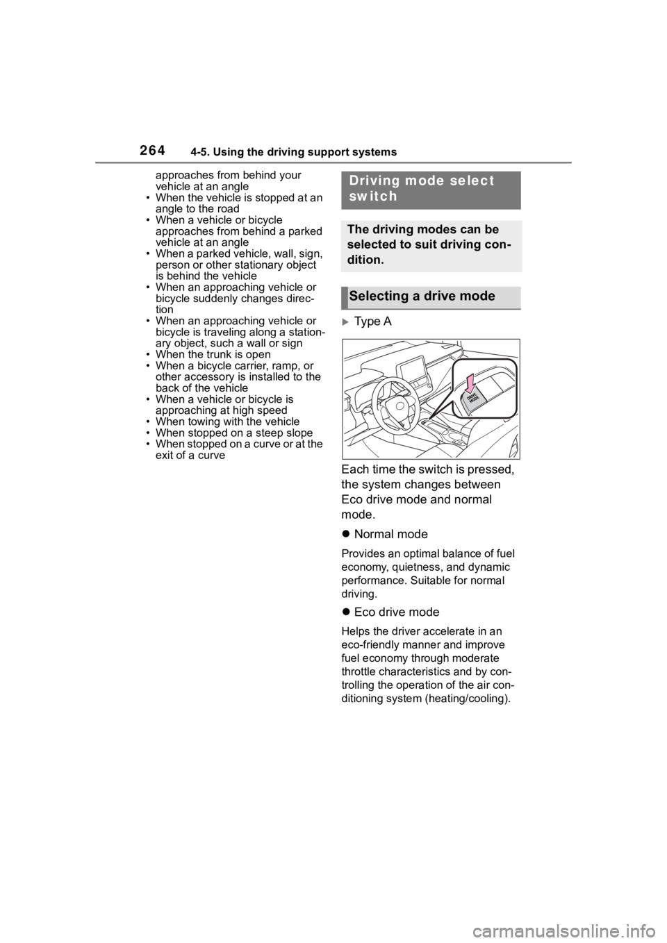
Type A
Each time the switch is pressed,
the system changes between
Eco drive mode and normal
mode.
Normal mode
Provides an optimal balance of fuel
economy, quietness, and dynamic
performance. Suitable for normal
driving.
Eco drive mode
Helps the driver accelerate in an
eco-friendly manner and improve
fuel economy through moderate
throttle characteristics and by con-
trolling the operation of the air con-
ditioning system (heating/cooling).
Driving mode select
switch
The driving modes can be
selected to suit driving con-
dition.
Selecting a drive mode
Page 281 of 496

2815-1. Using the air conditioning system and defogger
5
Interior features
the temperature setting or the
inside temperature.
■Eco air conditioning mode
When Eco drive mode is selected
using the driving mode select
switch, eco air conditioning mode
turns on.
When a drive mode other than Eco
drive mode is sele cted, eco air con-
ditioning mode may turn off.
■Operation of the air condition-
ing system in Eco drive mode
●In Eco drive mode, the air condi-
tioning system is controlled as fol-
lows to prioritize fuel efficiency:
• Engine speed and compressor operation controlled to restrict
heating/cooling capacity
• Fan speed restr icted when auto-
matic mode is selected
●To improve air co nditioning perfor-
mance, perform the following
operations:
• Turn off eco air conditioning mode ( P.280)
• Adjust the fan speed
• Turn off Eco drive mode ( P.264)
■When the outside temperature
falls to nearly 32°F (0°C)
The dehumidification function may
not operate even when “A/C” switch
is pressed.
■Ventilation and air conditioning
odors
●To let fresh air in, set the air condi-
tioning system to the outside air
mode.
●During use, various odors from
inside and outside the vehicle may
enter into and a ccumulate in the
air conditioning system. This may
then cause odor to be emitted
from the vents.
●To reduce potential odors from
occurring:
• It is recommended that the air conditioning system be set to out-
side air mode prior to turning the
vehicle off. • The start timing of the blower may
be delayed for a short period of
time immediately after the air con-
ditioning system is started in auto-
matic mode.
●When parking, the system auto-
matically switches to outside air
mode to encourage better air cir-
culation throughout the vehicle,
helping to reduce odors that occur
when starting the vehicle.
■Air conditioning filter
P.346
■Air conditioning system refrig-
erant
●A label regarding the refrigerant of
the air conditioning system is
attached to the e ngine compart-
ment at the locati on shown in the
following illustration.
●The meaning of each symbol on
the label are as follows:
Caution
Air conditioning sys-
tem
Air conditioning sys-
tem lubricant type
Requires registered
technician to service
air conditioning sys-
tem
Flammable refrigerant