Page 96 of 496
962-1. Instrument cluster
■Locations of gauges and meters
The units of measure may differ depending on the intended destination of
the vehicle.
Tachometer
Displays the engine speed in revolutions per minute
Outside temperature
Displays the outside temperature within the range of -40°F (-40 °C) to 140°F
(60°C)
Clock ( P. 9 8 )
Multi-information display
Presents the driver with a variety of vehicle data (P.102)
Displays warning messages if a malfunction occurs (P.382)
Speedometer
Fuel gauge
Displays the quantity of fu el remaining in the tank
Odometer and trip meter display ( P.97)
Shift position indicator ( P.180)
Engine coolant temperature gauge
Displays the engine c oolant temperature
Display change button ( P.97)
Gauges and meters (4.2-inch display)
Meter display
Page 98 of 496
982-1. Instrument cluster
■Display items
Odometer
Displays the total distance the vehi-
cle has been driven.
Trip meter A/Trip meter B
Displays the distan ce the vehicle
has been driven si nce the meter
was last reset. Trip meters A and B
can be used to record and display
different distances independently.
To reset, display the desired trip
meter and press and hold the dis-
play change button.
The brightness of the instrument
panel lights can be adjusted.
1 Brighter
2 Darker
■Instrument panel light bright-
ness adjustment
The brightness of the instrument
panel lights can be adjusted sepa-
rately for when the tail lights are on
and off.
■The clocks can be adjusted
on the audio system
screen.
Refer to “MULTIMEDIA
OWNER’S MANUAL”.
Changing the instrument
panel light brightness
Adjusting the clock
Page 99 of 496
992-1. Instrument cluster
2
Vehicle status information and indicators
■Locations of gauges and metersEngine coolant temperature gauge
Displays the engine c oolant temperature
Outside temperature
Displays the outside temperature within the range of -40°F (-40 °C) to 140°F
(60°C)
Hybrid System Indicator/Analog speedometer/Tachometer
Displays hybrid system output or regeneration level ( P.100)
This setting can be changed on the setting screen. ( P.442)
Clock ( P.102)
Fuel gauge
Displays the quantity of fu el remaining in the tank
Odometer and trip meter display ( P.101)
Shift position indicator ( P.180)
Multi-information display
Presents the driver with a variety of vehicle data (P.109)
Displays warning messages if a malfunction occurs (P.382)
Gauges and meters (7-inch display)
Meter display
Page 102 of 496

1022-1. Instrument cluster
■Instrument panel light bright-
ness adjustment
The brightness of the instrument
panel lights can be adjusted sepa-
rately for when the tail lights are on
and off.
■The clocks can be adjusted
on the audio system
screen.
Refer to “MULTIMEDIA
OWNER’S MANUAL”.
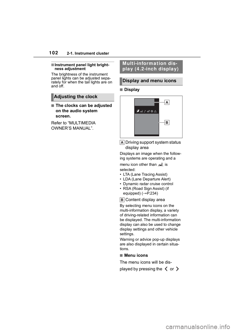
■Display
Driving support system status
display area
Displays an image when the follow-
ing systems are operating and a
menu icon other than is
selected:
• LTA (Lane Tracing Assist)
• LDA (Lane Departure Alert)
• Dynamic radar cruise control
• RSA (Road Sign Assist) (if equipped) ( P.234)
Content display area
By selecting menu icons on the
multi-information di splay, a variety
of driving-related information can
be displayed. The multi-information
display can also be used to change
display settings and other vehicle
settings.
Warning or advice pop-up displays
are also displayed in certain situa-
tions.
■Menu icons
The menu icons will be dis-
played by pressing the or
Adjusting the clock
Multi-infor mation dis-
play (4.2-inch display)
Display and menu icons
Page 278 of 496
2785-1. Using the air conditioning system and defogger
5-1.Using the air conditioning system and defogger
Temperature control switch
Fan speed control switch
“A/C” switch
Outside air mode switch
Recirculated air mode switch
Eco air conditioning mode switch
Airflow mode control switch
Rear window defogger and outside rear view mirror defoggers
switch
*
Windshield defogger switch
Off switch
Automatic mode switch
Rear window defogger switch
*
*: If equipped
■Adjusting the temperature
setting
To adjust the temperature set- ting, turn the temperature con-
trol switch clockwise (warm) or
counterclockwise (cool).
If “A/C” switch is not pressed, the
Automatic air conditioning system
Air outlets are automatically selected and fan speed is auto-
matically adjusted according to the set temperature setting.
Also, the display and button positions will differ depending on
the type of the system.
Air conditioning controls
Page 279 of 496

2795-1. Using the air conditioning system and defogger
5
Interior features
system will blow ambient tempera-
ture air or heated air.
■Setting the fan speed
To adjust the fan speed, turn the
fan speed control switch clock-
wise (increase) or counterclock-
wise (decrease).
Pressing the off switch to turns off
the fan.
■Change the airflow mode
Press the airflow mode control
switch.
The airflow mode changes as fol-
lows each time the switch is
pressed.
1 Upper body
2 Upper body and feet
3 Feet
4 Feet and the windshield
defogger operates
■Switching between outside
air and recirculated air
modes
To change to recirculated air
mode, press the recirculated air mode switch.
The indicator illuminates on the
recirculated air mode switch.
To change to outside air
mode, press the outside air
mode switch.
The indicator illuminates on the out-
side air mode switch.
■Set cooling and dehumidifi-
cation function
Press the “A/C” switch.
When the function is on, the indica-
tor illuminates on the “A/C” switch.
■Defogging the windshield
Defoggers are used to defog the
windshield and front side win-
dows.
Press the windshield defogger
switch.
Set the outside/recirculated air
mode switch to outside air mode if
the recirculated air mode is used. (It
may switch automatically.)
To defog the windshield and the
side windows quickly, turn the air
flow and temperature up.
To return to the previous mode,
press the windshield defogger
switch again when the windshield is
defogged.
When the windshield defogger
switch is on, the indicator illumi-
nates on the windshield defogger
switch.
Page 319 of 496

3196-3. Do-it-yourself maintenance
6
Maintenance and care
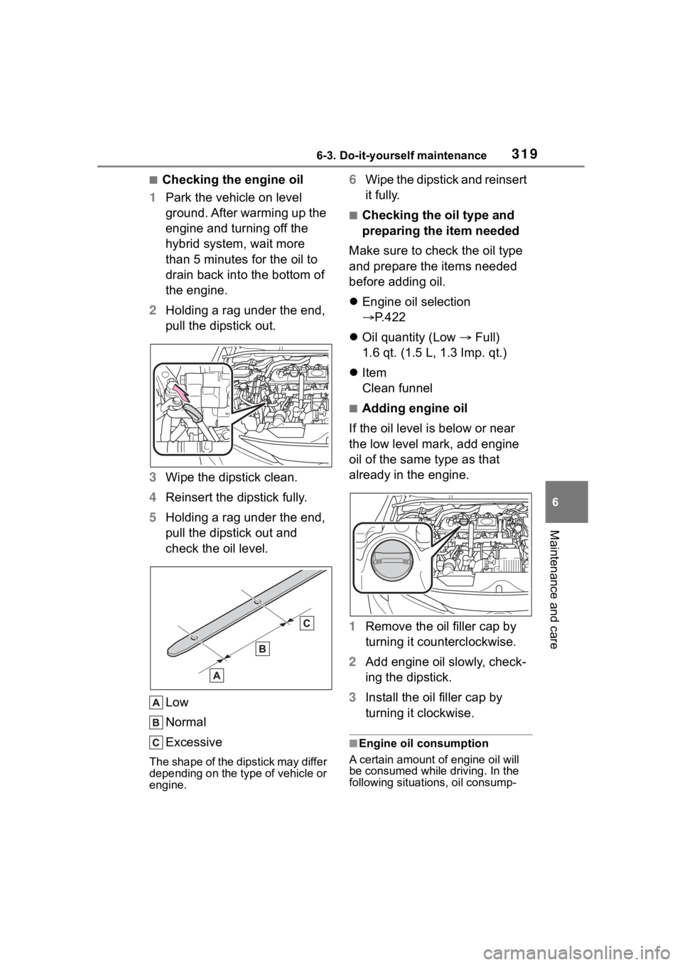
■Checking the engine oil
1 Park the vehicle on level
ground. After warming up the
engine and turning off the
hybrid system, wait more
than 5 minutes for the oil to
drain back into the bottom of
the engine.
2 Holding a rag under the end,
pull the dipstick out.
3 Wipe the dipstick clean.
4 Reinsert the dipstick fully.
5 Holding a rag under the end,
pull the dipstick out and
check the oil level.
Low
Normal
Excessive
The shape of the dipstick may differ
depending on the type of vehicle or
engine.
6Wipe the dipstick and reinsert
it fully.
■Checking the oil type and
preparing the item needed
Make sure to check the oil type
and prepare the items needed
before adding oil.
Engine oil selection
P.422
Oil quantity (Low Full)
1.6 qt. (1.5 L, 1.3 Imp. qt.)
Item
Clean funnel
■Adding engine oil
If the oil level is below or near
the low level mark, add engine
oil of the same type as that
already in the engine.
1 Remove the oil filler cap by
turning it counterclockwise.
2 Add engine oil slowly, check-
ing the dipstick.
3 Install the oil filler cap by
turning it clockwise.
■Engine oil consumption
A certain amount of engine oil will
be consumed while driving. In the
following situatio ns, oil consump-
Page 358 of 496
3586-3. Do-it-yourself maintenance
3Pull the cover toward the rear
of the vehicle and remove the
cover.
4 Remove the 2 screws and
then remove the light assem-
bly by pulling it straight back.
5 Turn the bulb base counter-
clockwise.
Rear side marker lights
Rear turn signal lights 6
Remove the light bulb.
Rear side marker lights
Rear turn signal lights
7 When installing the light bulb,
install it by conducting steps
6 and 5 with the directions
reversed.
8 Install the light assembly and
then install the 2 screws.
Align the guide and pin on
the light assembl y with the mount-
ing when installing it.
9 Install the cover.
■Rear turn signal lights
(vehicles with LED type rear
side marker lights)
1 Open the trunk lid.
2 Insert a flathead screwdriver
between the cover and the
light assembly and pry up the