Page 15 of 496
15Pictorial index
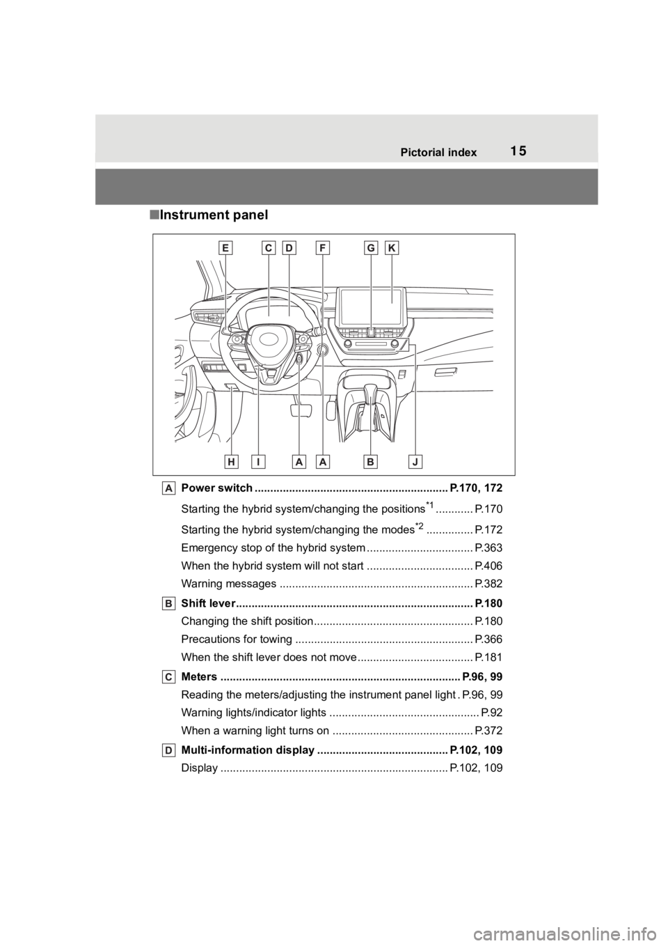
■Instrument panel
Power switch ................................................... ........... P.170, 172
Starting the hybrid syst em/changing the positions
*1............ P.170
Starting the hybrid system/changing the modes
*2............... P.172
Emergency stop of the hybrid system ............................ ...... P.363
When the hybrid system will not start .......................... ........ P.406
Warning messages ............................................... ............... P.382
Shift lever.................................................... ........................ P.180
Changing the shift position.................................... ............... P.180
Precautions for towing .. ....................................... ................ P.366
When the shift lever does not move............................. ........ P.181
Meters ............................................................................. P.96, 99
Reading the meters/adjusting the instrument panel light . P.96, 9 9
Warning lights/indicator lights ................................ ................ P.92
When a warning light turns on .................................. ........... P.372
Multi-information display . ......................................... P.102, 109
Display ........................................................ ................. P.102, 109
Page 17 of 496
17Pictorial index
■Switches
Instrument panel light cont rol dial ............................. P.98, 101
Automatic High Beam switch ..................................... ...... P.191
VSC OFF switch
*............................................................... .P.267
Heated steering wheel switch
*.......................................... P.284
Windshield wiper de-icer switch
*..................................... P.282
Fuel filler door opener swi tch ........................................... P.197
Outside rear view mirror s witch ....................................... P.148
Door lock switches ............................................................ P.131
Power window switches ....... ............................................. P.150
Window lock switch ............................................. .............. P.152
*: If equipped
Page 36 of 496
361-1. For safe use
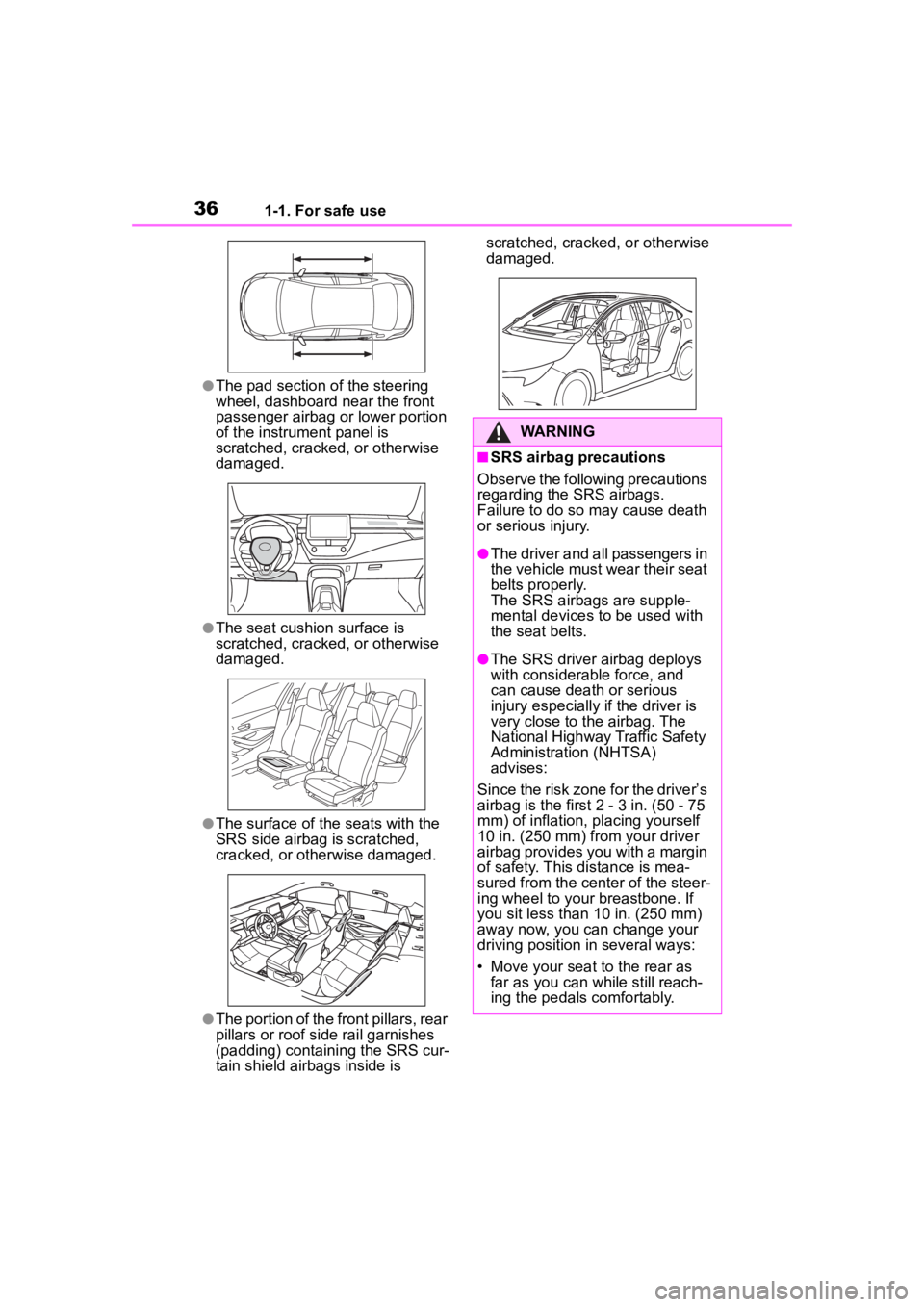
●The pad section of the steering
wheel, dashboard near the front
passenger airbag or lower portion
of the instrument panel is
scratched, cracked, or otherwise
damaged.
●The seat cushion surface is
scratched, cracked, or otherwise
damaged.
●The surface of the seats with the
SRS side airbag is scratched,
cracked, or otherwise damaged.
●The portion of the front pillars, rear
pillars or roof side rail garnishes
(padding) containing the SRS cur-
tain shield airbags inside is scratched, cracked, or otherwise
damaged.
WARNING
■SRS airbag precautions
Observe the following precautions
regarding the SRS airbags.
Failure to do so may cause death
or serious injury.
●The driver and all passengers in
the vehicle must wear their seat
belts properly.
The SRS airbags are supple-
mental devices to be used with
the seat belts.
●The SRS driver airbag deploys
with considerable force, and
can cause death or serious
injury especially if the driver is
very close to the airbag. The
National Highway Traffic Safety
Administration (NHTSA)
advises:
Since the risk zone for the driver’s
airbag is the first 2 - 3 in. (50 - 75
mm) of inflation, placing yourself
10 in. (250 mm) from your driver
airbag provides you with a margin
of safety. This distance is mea-
sured from the center of the steer-
ing wheel to your breastbone. If
you sit less than 10 in. (250 mm)
away now, you can change your
driving position in several ways:
• Move your seat to the rear as far as you can while still reach-
ing the pedals comfortably.
Page 38 of 496
381-1. For safe use
WARNING
●Improperly seated and/or
restrained infants and children
can be killed or seriously injured
by a deploying airbag. An infant
or child who is too small to use
a seat belt should be properly
secured using a child restraint
system. Toyota strongly recom-
mends that all infants and chil-
dren be placed in the rear seats
of the vehicle and properly
restrained. The rear seats are
safer for infants and children
than the front passenger seat.
(
P. 4 8 )
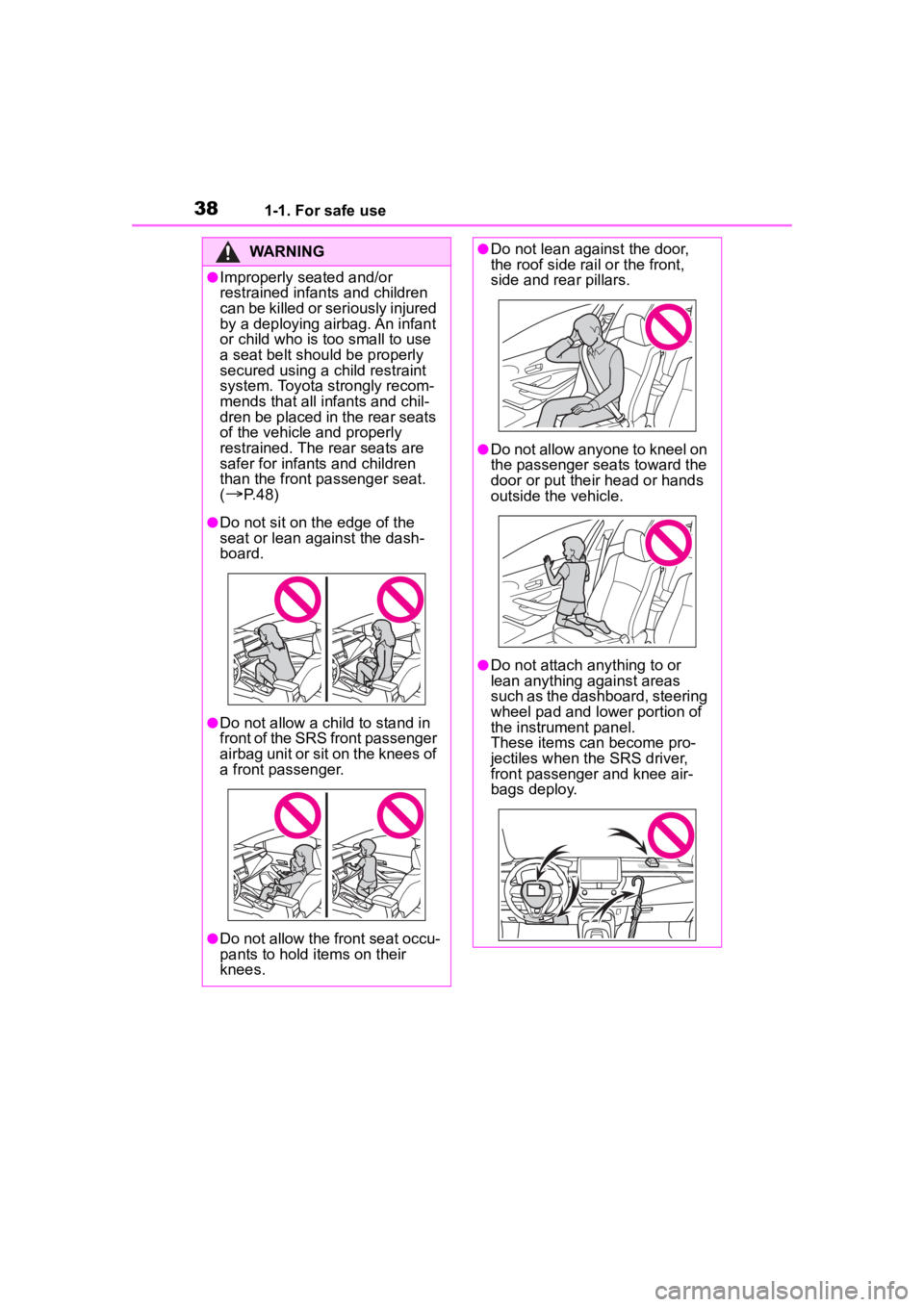
●Do not sit on the edge of the
seat or lean against the dash-
board.
●Do not allow a child to stand in
front of the SRS front passenger
airbag unit or sit on the knees of
a front passenger.
●Do not allow the front seat occu-
pants to hold items on their
knees.
●Do not lean against the door,
the roof side rail or the front,
side and rear pillars.
●Do not allow anyone to kneel on
the passenger seats toward the
door or put their head or hands
outside the vehicle.
●Do not attach anything to or
lean anything against areas
such as the dashboard, steering
wheel pad and lower portion of
the instrument panel.
These items can become pro-
jectiles when th e SRS driver,
front passenger and knee air-
bags deploy.
Page 40 of 496
401-1. For safe use
WARNING
■Modification and disposal of
SRS airbag system compo-
nents
Do not dispose of your vehicle or
perform any of the following modi-
fications without consulting your
Toyota dealer. The SRS airbags
may malfunction or deploy
(inflate) accidentally, causing
death or serious injury.
●Installation, removal, disassem-
bly and repair of the SRS air-
bags
●Repairs, modifications, removal
or replacement of the steering
wheel, instrument panel, dash-
board, seats or seat upholstery,
front, side and rear pillars, roof
side rails, front door panels,
front door trims or front door
speakers
●Modifications to the front door
panel (such as making a hole in
it)
●Repairs or modifications of the
front fender, front bumper, or
side of the occ upant compart-
ment
●Installation of a grille guard (bull
bars, kangaroo bar, etc.), snow
plows, winches or roof luggage
carrier
●Modifications to the vehicle’s
suspension system
●Installation of electronic devices
such as mobile two-way radios
and CD players
●Modifications to your vehicle for
a person with a physical disabil-
ity
Page 92 of 496
922-1. Instrument cluster
2-1.Instrument cluster
For the purpose of explanation, the following illustrations display all
warning lights and indicators illuminated.
4.2-inch display
7-inch display
War ning lights and indicators
The warning lights and indicators on the instrument cluster,
center panel, overhead console and outside rear view mirrors
inform the driver of the status of the vehicle’s various sys-
tems.
Warning lights and indicators displayed on the instru-
ment cluster
Page 95 of 496
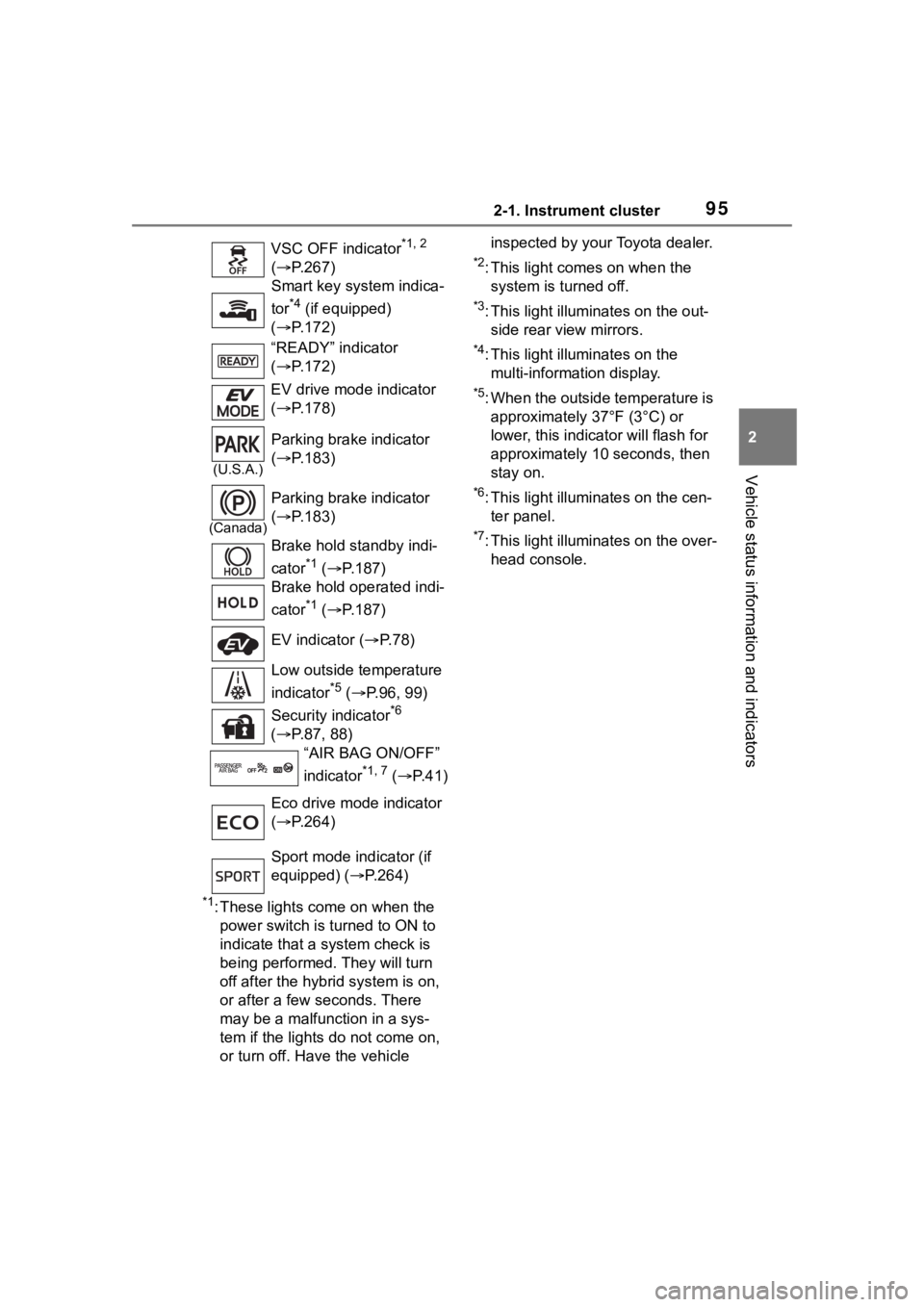
952-1. Instrument cluster
2
Vehicle status information and indicators
*1: These lights come on when the power switch is turned to ON to
indicate that a system check is
being performed. They will turn
off after the hybrid system is on,
or after a few seconds. There
may be a malfunction in a sys-
tem if the lights do not come on,
or turn off. Have the vehicle inspected by your Toyota dealer.
*2: This light comes on when the
system is turned off.
*3: This light illuminates on the out-side rear view mirrors.
*4: This light illuminates on the multi-information display.
*5: When the outside temperature is approximately 37°F (3°C) or
lower, this indicator will flash for
approximately 10 seconds, then
stay on.
*6: This light illuminates on the cen-ter panel.
*7: This light illuminates on the over-head console.
VSC OFF indicator
*1, 2
( P.267)
Smart key system indica-
tor
*4 (if equipped)
( P.172)
“READY” indicator
( P.172)
EV drive mode indicator
( P.178)
(U.S.A.)
Parking brake indicator
( P.183)
(Canada)
Parking brake indicator
( P.183)
Brake hold standby indi-
cator
*1 ( P.187)
Brake hold operated indi-
cator
*1 ( P.187)
EV indicator ( P. 7 8 )
Low outside temperature
indicator
*5 ( P.96, 99)
Security indicator
*6
( P.87, 88)
“AIR BAG ON/OFF”
indicator
*1, 7 ( P. 4 1 )
Eco drive mode indicator
( P.264)
Sport mode indicator (if
equipped) ( P.264)
Page 98 of 496
982-1. Instrument cluster
■Display items
Odometer
Displays the total distance the vehi-
cle has been driven.
Trip meter A/Trip meter B
Displays the distan ce the vehicle
has been driven si nce the meter
was last reset. Trip meters A and B
can be used to record and display
different distances independently.
To reset, display the desired trip
meter and press and hold the dis-
play change button.
The brightness of the instrument
panel lights can be adjusted.
1 Brighter
2 Darker
■Instrument panel light bright-
ness adjustment
The brightness of the instrument
panel lights can be adjusted sepa-
rately for when the tail lights are on
and off.
■The clocks can be adjusted
on the audio system
screen.
Refer to “MULTIMEDIA
OWNER’S MANUAL”.
Changing the instrument
panel light brightness
Adjusting the clock