2023 TOYOTA COROLLA CROSS wheel torque
[x] Cancel search: wheel torquePage 86 of 500

862-1. Instrument cluster
type and drive information items
were selected in . (P.86)
After start
• Distance: Displays the distance
driven since e ngine start
• Elapsed time: Displays the elapsed time since engine start
• Average vehicle speed: Displays the average vehi cle speed since
engine start
After reset
• Distance: Displays the distance
driven since the display was
reset
*
• Elapsed time: Displays the elapsed time since the display
was reset
*
• Average vehicle speed: Displays the average vehi cle speed since
the display was reset
*
*
: To reset, display the desired item
and press and hold the
meter control switch.
■Tire pressure
P. 3 5 3
■AWD operation status dis-
play (if equipped)
The illustration used is intended as an example, and may differ from the
image that is actually displayed on
the multi-information display.
Torque distribution display
Displays the drive status of each
wheel in 6 steps from 0 to 5.
■Meter display settings that
can be changed
Language
Select to change the language dis-
played.
Units
Select to change the units of mea-
sure displayed.
Eco Driving Indicator Light
Select to enable/disable the Eco
Driving Indi cator Light.
Fuel economy display
Select to change the average fuel
consumption display between after
start/after reset. ( P. 8 3 )
Select to displa y/not display the
audio system linked display.
Select to change the displayed con-
tent of the following:
• Drive information type
Select to change the drive informa-
tion type display between after
start/after reset.
• Drive information items
Settings display
Page 92 of 500
922-1. Instrument cluster
Route guidance to destination
Compass display (head-
ing-up display)
Select to enable selection of an
audio source or track on the
meter using the meter control
switches.
This menu icon can be set to be
displayed/not displayed in .
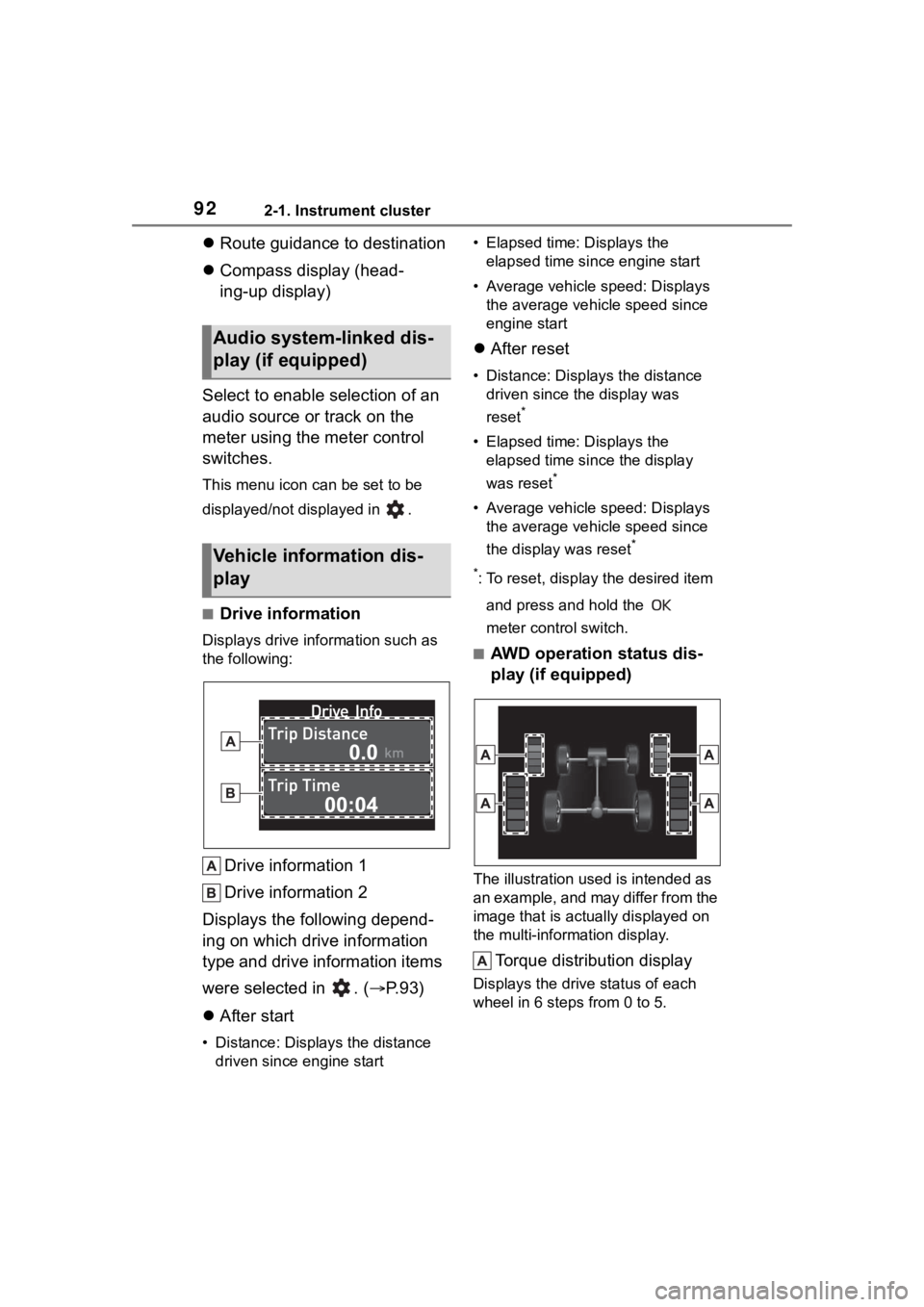
■Drive information
Displays drive information such as
the following:
Drive information 1
Drive information 2
Displays the following depend-
ing on which drive information
type and drive information items
were selected in . ( P.93)
After start
• Distance: Displays the distance
driven since e ngine start • Elapsed time: Displays the
elapsed time since engine start
• Average vehicle speed: Displays the average vehicle speed since
engine start
After reset
• Distance: Displays the distance
driven since the display was
reset
*
• Elapsed time: Displays the elapsed time since the display
was reset
*
• Average vehicle speed: Displays the average vehicle speed since
the display was reset
*
*
: To reset, display the desired item and press and hold the
meter control switch.
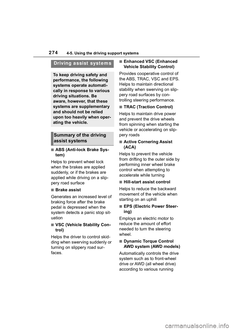
■AWD operation status dis-
play (if equipped)
The illustration used is intended as
an example, and may differ from the
image that is actually displayed on
the multi-information display.
Torque distribution display
Displays the drive status of each
wheel in 6 steps from 0 to 5.
Audio system-linked dis-
play (if equipped)
Vehicle information dis-
play
Page 274 of 500
2744-5. Using the driving support systems
■ABS (Anti-lock Brake Sys-
tem)
Helps to prevent wheel lock
when the brakes are applied
suddenly, or if the brakes are
applied while driving on a slip-
pery road surface
■Brake assist
Generates an increased level of
braking force after the brake
pedal is depressed when the
system detects a panic stop sit-
uation
■VSC (Vehicle Stability Con-
trol)
Helps the driver to control skid-
ding when swerving suddenly or
turning on slippery road sur-
faces.
■Enhanced VSC (Enhanced
Vehicle Stability Control)
Provides cooperative control of
the ABS, TRAC, VSC and EPS.
Helps to maintain directional
stability when swerving on slip-
pery road surfaces by con-
trolling steering performance.
■TRAC (Traction Control)
Helps to maintain drive power
and prevent the drive wheels
from spinning when starting the
vehicle or accelerating on slip-
pery roads
■Active Cornering Assist
(ACA)
Helps to prevent the vehicle
from drifting to the outer side by
performing inner wheel brake
control when attempting to
accelerate while turning
■Hill-start assist control
Helps to reduce the backward
movement of the vehicle when
starting on an uphill
■EPS (Electric Power Steer-
ing)
Employs an electric motor to
reduce the amount of effort
needed to turn the steering
wheel.
■Dynamic Torque Control
AWD system (AWD models)
Automatically controls the drive
system such as to front-wheel
drive or AWD (all wheel drive)
according to various running
Driving assist systems
To keep driving safety and
performance, the following
systems operate automati-
cally in response to various
driving situations. Be
aware, however, that these
systems are supplementary
and should not be relied
upon too heavily when oper-
ating the vehicle.
Summary of the driving
assist systems
Page 408 of 500

4087-2. Steps to take in an emergency
When replacing tires on a vehi-
cle with wheel lock nuts, use the
following procedures to remove
and install the wheel lock nuts.
The wheel lock key is stored in
the tray inside the luggage com-
partment. Always return the
wheel lock key to its original
position after use, so that it does
not get lost. (P.406)
■Removal
For ease of removal, the wheel
lock nut should always be the
first one loosened.
1 Place the wheel lock key on
top of the wheel lock nut,
turning until the wheel lock
key and wheel lock nut pat-
terns engage.
2 Place the wheel nut wrench
on the wheel lock key, and
while applying pressure on
the wheel lock key, loosen
the wheel lock nut.
■Installation
For ease of installation, the
wheel lock nut should always be
the last one tightened.
1 By hand, install a wheel lock
nut on the wheel to be
installed.
2 Place the wheel lock key on
top of the wheel lock nut,
turning until the wheel lock
key and wheel lock nut pat-
terns engage.
3 Place the wheel nut wrench
on the wheel lock key, and
while applying pressure on
the wheel lock key, tighten
the wheel lock nut to the rec-
ommended torque.
WARNING
●Do not raise the vehicle while
someone is inside.
●When raising the vehicle, do not
put an object on or under the
jack.
●Do not raise the vehicle to a
height greater than that required
to replace the tire.
●Use a jack stand if it is neces-
sary to get under the vehicle.
●When lowering the vehicle,
make sure that there is no-one
near the vehicle. If there are
people nearby, warn them
vocally before lowering.
Wheel lock nut (if
equipped)
NOTICE
■When using a wheel lock key
(if equipped)
Do not use an impact wrench.
Using an impact wrench may
cause permanent damage to
wheel lock nut and wheel lock
key. If in doubt about wheel lock
application, contact your Toyota
dealer.
Page 413 of 500
4137-2. Steps to take in an emergency
7
When trouble arises
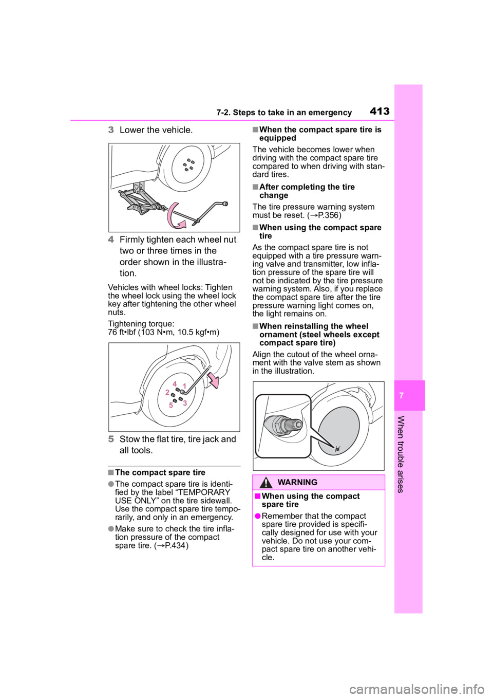
3Lower the vehicle.
4 Firmly tighten each wheel nut
two or three times in the
order shown in the illustra-
tion.
Vehicles with wheel locks: Tighten
the wheel lock using the wheel lock
key after tightening the other wheel
nuts.
Tightening torque:
76 ft•lbf (103 N•m, 10.5 kgf•m)
5Stow the flat tire, tire jack and
all tools.
■The compact spare tire
●The compact spare tire is identi-
fied by the label “TEMPORARY
USE ONLY” on the tire sidewall.
Use the compact spare tire tempo-
rarily, and only in an emergency.
●Make sure to check the tire infla-
tion pressure of the compact
spare tire. ( P.434)
■When the compact spare tire is
equipped
The vehicle becomes lower when
driving with the compact spare tire
compared to when driving with stan-
dard tires.
■After completing the tire
change
The tire pressure warning system
must be reset. ( P.356)
■When using the compact spare
tire
As the compact spare tire is not
equipped with a tire pressure warn-
ing valve and transm itter, low infla-
tion pressure of the spare tire will
not be indicated by the tire pressure
warning system. Also , if you replace
the compact spare ti re after the tire
pressure warning light comes on,
the light remains on.
■When reinstalling the wheel
ornament (steel wheels except
compact spare tire)
Align the cutout of the wheel orna-
ment with the valve stem as shown
in the illustration.
WARNING
■When using the compact
spare tire
●Remember that the compact
spare tire provided is specifi-
cally designed for use with your
vehicle. Do not use your com-
pact spare tire on another vehi-
cle.
Page 434 of 500
4348-1. Specifications
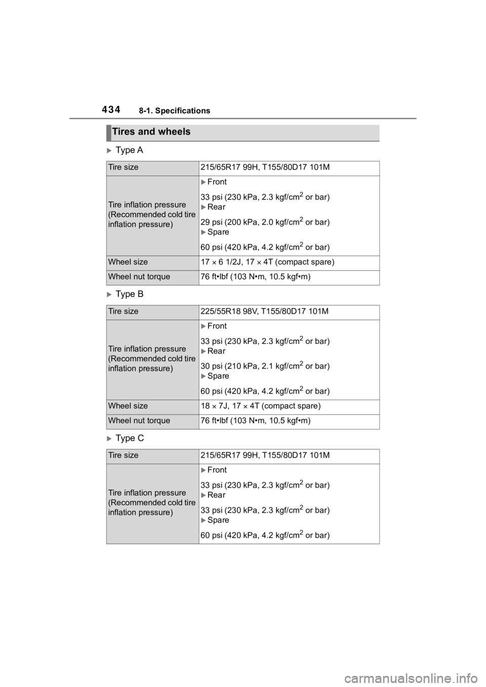
Ty p e A
Ty p e B
Ty p e C
Tires and wheels
Tire size215/65R17 99H, T155/80D17 101M
Tire inflation pressure
(Recommended cold tire
inflation pressure)
Front
33 psi (230 kPa, 2.3 kgf/cm
2 or bar)
Rear
29 psi (200 kPa, 2.0 kgf/cm
2 or bar)
Spare
60 psi (420 kPa, 4.2 kgf/cm
2 or bar)
Wheel size17 6 1/2J, 17 4T (compact spare)
Wheel nut torque76 ft•lbf (103 N•m, 10.5 kgf•m)
Tire size225/55R18 98V, T155/80D17 101M
Tire inflation pressure
(Recommended cold tire
inflation pressure)
Front
33 psi (230 kPa, 2.3 kgf/cm
2 or bar)
Rear
30 psi (210 kPa, 2.1 kgf/cm
2 or bar)
Spare
60 psi (420 kPa, 4.2 kgf/cm
2 or bar)
Wheel size18 7J, 17 4T (compact spare)
Wheel nut torque76 ft•lbf (103 N•m, 10.5 kgf•m)
Tire size215/65R17 99H, T155/80D17 101M
Tire inflation pressure
(Recommended cold tire
inflation pressure)
Front
33 psi (230 kPa, 2.3 kgf/cm
2 or bar)
Rear
33 psi (230 kPa, 2.3 kgf/cm
2 or bar)
Spare
60 psi (420 kPa, 4.2 kgf/cm
2 or bar)
Page 435 of 500
4358-1. Specifications
8
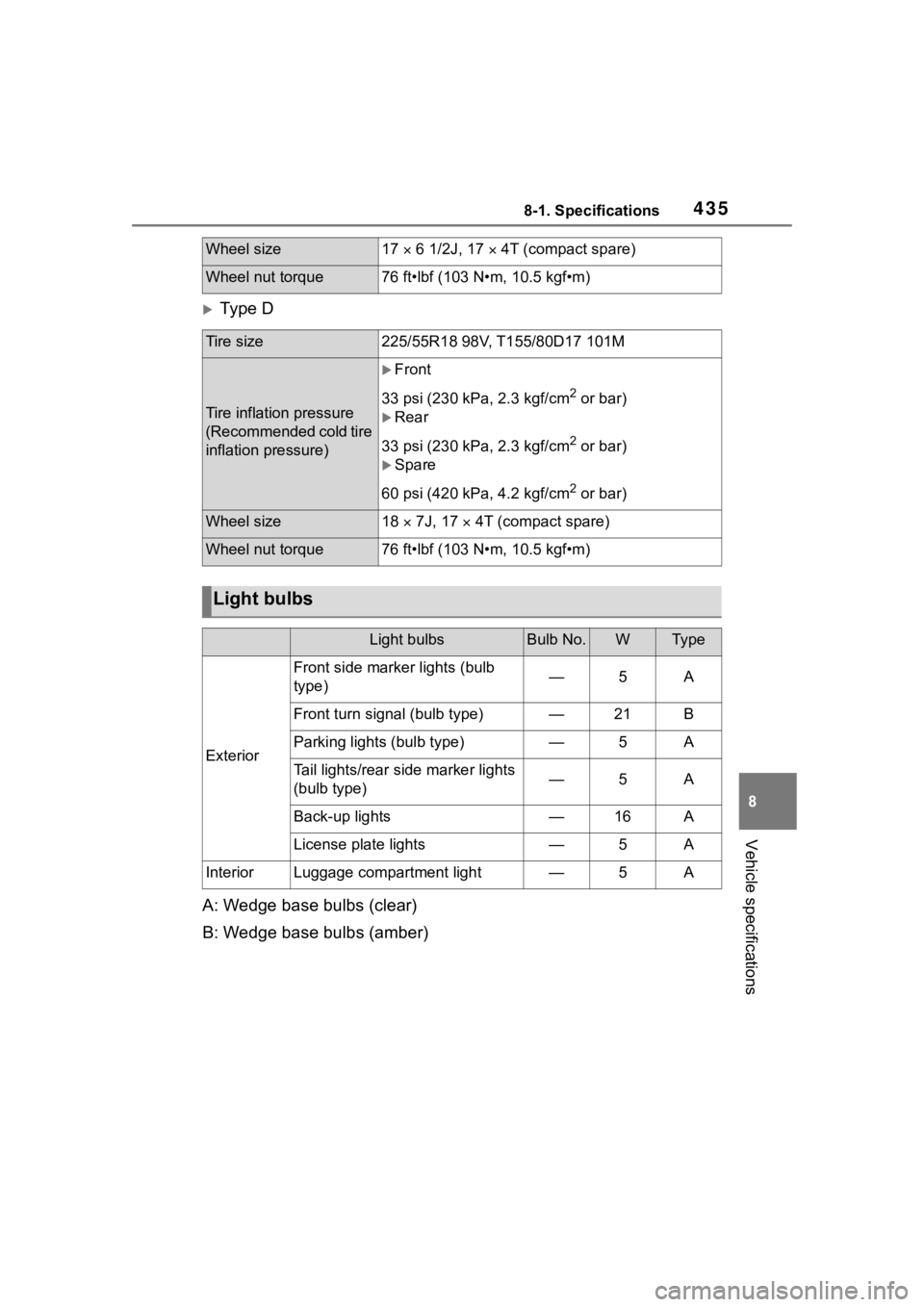
Vehicle specifications
Ty p e D
A: Wedge base bulbs (clear)
B: Wedge base bulbs (amber)
Wheel size17 6 1/2J, 17 4T (compact spare)
Wheel nut torque76 ft•lbf (103 N•m, 10.5 kgf•m)
Tire size225/55R18 98V, T155/80D17 101M
Tire inflation pressure
(Recommended cold tire
inflation pressure)
Front
33 psi (230 kPa, 2.3 kgf/cm
2 or bar)
Rear
33 psi (230 kPa, 2.3 kgf/cm
2 or bar)
Spare
60 psi (420 kPa, 4.2 kgf/cm
2 or bar)
Wheel size18 7J, 17 4T (compact spare)
Wheel nut torque76 ft•lbf (103 N•m, 10.5 kgf•m)
Light bulbs
Light bulbsBulb No.WTy p e
Exterior
Front side marker lights (bulb
type)—5A
Front turn signal (bulb type)—21B
Parking lights (bulb type)—5A
Tail lights/rear side marker lights
(bulb type)—5A
Back-up lights—16A
License plate lights—5A
InteriorLuggage compartment light—5A