Page 375 of 500

3756-3. Do-it-yourself maintenance
6
Maintenance and care
High mounted stoplight
■LED light bulbs
The lights other than the following
lights each consist of a number of
LEDs. If any of the LEDs burn out,
take your vehicle to your Toyota
dealer to have the light replaced.
●Front side marker lights (bulb
type)
●Parking lights (bulb type)
●Front turn signal lights (bulb type)
●Tail lights/rear side marker lights
(bulb type)
●Back-up lights
●License plate lights
■Condensation build-up on the
inside of the lens
Temporary condensation build-up
on the inside of the headlight lens
does not indicate a malfunction.
Contact your Toyota dealer for more
information in the following situa-
tions:
●Large drops of water have built up
on the inside of the lens.
●Water has built up inside the
headlight.
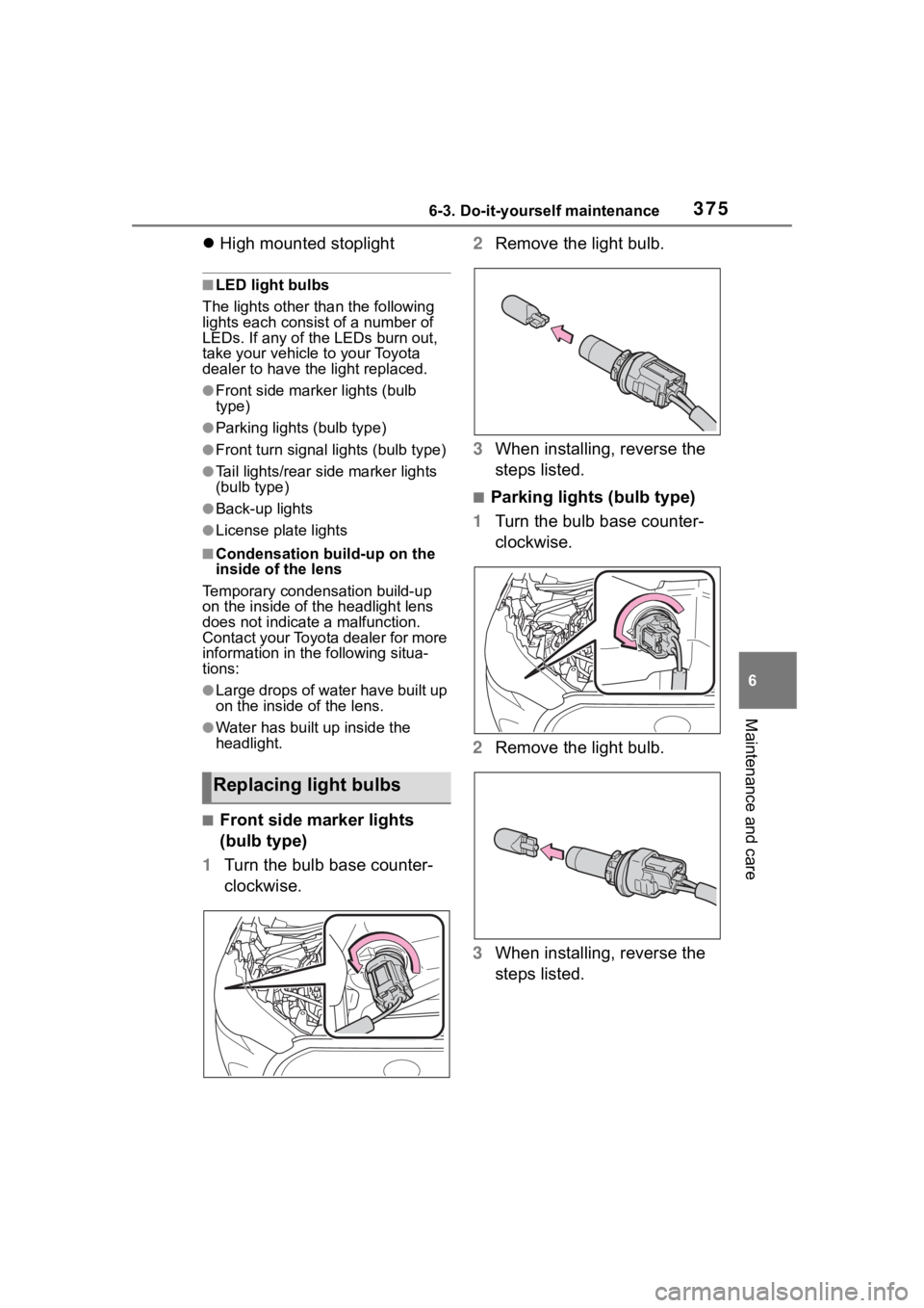
■Front side marker lights
(bulb type)
1 Turn the bulb base counter-
clockwise. 2
Remove the light bulb.
3 When installing, reverse the
steps listed.
■Parking lights (bulb type)
1 Turn the bulb base counter-
clockwise.
2 Remove the light bulb.
3 When installing, reverse the
steps listed.
Replacing light bulbs
Page 376 of 500
3766-3. Do-it-yourself maintenance
■Front turn signal lights
(bulb type)
1 Turn the bulb base counter-
clockwise.
2 Remove the light bulb.
3 When installing, reverse the
steps listed.
■Tail lights/rear side marker
lights (bulb type)
1 Open the back door.
2 Remove the 2 screws and
then remove the light unit by
pulling it straight back. 3
Turn the bulb base counter-
clockwise.
4 Remove the light bulb.
5 When installing the light bulb,
install it by conducting steps
4 and 3 with the directions
reversed.
6 Install the light unit.
Align the 2 guides and push the
light unit toward the front of the
vehicle to install it.
Page 377 of 500
3776-3. Do-it-yourself maintenance
6
Maintenance and care
7Install the 2 screws.
■Back-up lights
1 Open the back door and
remove the cover.
Using a flathead screwdriver,
remove the cover.
To prevent damage to the vehicle,
wrap the tip of the flathead screw-
driver with tape, etc.
2Turn the bulb base counter-
clockwise and remove it. 3
Remove the light bulb.
4 When installing the light bulb,
install it by conducting steps
3 and 2 with the directions
reversed.
5 Install the cover.
Align the tabs of the cover with the
grooves and install the cover.
Page 378 of 500
3786-3. Do-it-yourself maintenance
■License plate lights
1 Remove the lens.
Lens
Hook
1 Insert a small flathead screw-
driver, etc. into either the
right or left hole of the lens.
2 Push the screwdriver side-
ways in the direction of the
arrow shown in the illustra-
tion, disengage the hook, and
then remove the lens.
To prevent damage to the vehicle,
wrap the tip of the screwdriver with
tape, etc.
2Remove the light bulb.
3 Install a new light bulb.
4 Install the lens.
Hooks
1 Fit the lens into either the
Page 379 of 500

3796-3. Do-it-yourself maintenance
6
Maintenance and care
right or left hooks.
2 Push the lens into place.
After installation, confirm that the
lens is properly installed by gently
pulling it.
WARNING
■To prevent injury
Before performing any light bulb
replacement procedure, be sure
to turn the e ngine switch off. Fail-
ure to do so may result in burns
from hot compone nts or a part of
your body may get caught on an
operating component, possibly
causing serious injury.
■Replacing light bulbs
●Turn off the lights. Do not
attempt to replace the bulb
immediately after turning off the
lights. The bulbs become very
hot and may cause burns.
●Do not touch the glass portion
of the light bulb with bare
hands. When it is unavoidable
to hold the glass portion, use
and hold with a clean dry cloth
to avoid getting moisture and
oils on the bulb. Also, if the bulb
is scratched or dropped, it may
blow out or crack.
●Fully install light bulbs and any
parts used to secure them. Fail-
ure to do so may result in heat
damage, fire, or water entering
the light unit. This may damage
the lights or cause condensa-
tion to build up on the lens.
■To prevent damage or fire
●Make sure bulbs are fully
seated and locked.
●Check the wattage of the bulb
before installing to prevent heat
damage.
Page 380 of 500
3806-3. Do-it-yourself maintenance
Page 400 of 500

4007-2. Steps to take in an emergency
WARNING
●Avoid abrupt maneuvering and
braking.
If the vehicle tires deteriorate,
you could lose control of the
steering wheel or the brakes.
■If a blowout or sudden air
leakage should occur
The tire pressure warning system
may not activate immediately.
■Maintenance of the tires
Each tire, including the spare (if
provided), should be checked
monthly when cold and inflated to
the inflation pressure recom-
mended by the vehicle manufac-
turer on the vehicle placard or tire
inflation pressure label (tire and
load information label). (If your
vehicle has tires of a different size
than the size indicated on the
vehicle placard or tire inflation
pressure label [tire and load infor-
mation label], you should deter-
mine the proper tire inflation
pressure for those tires.)
As an added safe ty feature, your
vehicle has been equipped with a
tire pressure m onitoring system
(TPMS-tire pressure warning sys-
tem) that illuminates a low tire
pressure telltale (tire pressure
warning light) when one or more
of your tires is significantly
under-inflated. Accordingly, when
the low tire pressure telltale (tire
pressure warning light) illumi-
nates, you should stop and check
your tires as soon as possible,
and inflate them to the proper
pressure. Driving on a signifi-
cantly under-inflated tire causes
the tire to overheat and can lead
to tire failure. Under-inflation also
reduces fuel efficiency and tire
tread life, and may affect the vehi-
cle’s handling and stopping ability.
Please note that the TPMS (tire
pressure warning system) is not a
substitute for proper tire mainte-
nance, and it is the driver’s
responsibility to m aintain correct
tire pressure, even if under-infla-
tion has not reached the level to
trigger illumination of the TPMS
low tire pressure te lltale (tire pres-
sure warning light).
Your vehicle has also been
equipped with a TPMS (tire pres-
sure warning system) malfunc-
tion indicator to indicate when the
system is not operating properly.
The TPMS (tire pressure warning
system) malfunction indicator is
combined with the low tire pres-
sure telltale (tire pressure warning
light). When the system detects a
malfunction, the te lltale will flash
for approximately one minute and
then remain continuously illumi-
nated. This sequence will con-
tinue upon subsequent vehicle
start-ups as long as the malfunc-
tion exists. When the malfunction
indicator is illuminated, the sys-
tem may not be ab le to detect or
signal low tire pressure as
intended.
TPMS (tire pressure warning sys-
tem) malfunctions may occur for a
variety of reasons, including the
installation of replacement or
alternate tires or wheels on the
vehicle that prevent the TPMS
(tire pressure warning system)
from functioning properly. Always
check the TPMS (tire pressure
warning system) malfunction tell-
tale after replacing one or more
tires or wheels on your vehicle to
ensure that the replacement or
alternate tires and wheels allow
the TPMS (tire pressure warning
system) to continue to function
properly.
Page 404 of 500

4047-2. Steps to take in an emergency
●LDA (Lane Departure Alert)
●AHB (Automatic High Beam)
●Dynamic radar cruise control
Follow the followi ng correction
methods.
• Check if there is any foreign mat- ter attached to the radar sensor or
radar sensor cover and clean
them if necessary ( P.192)
• This message may be displayed when driving in an open area with
few nearby vehicles or structures,
such as a desert, grasslands, sub-
urbs, etc.
The message may be cleared by
driving the vehicle in an area with
structures, vehicles, etc., nearby.
■If “System Stopped Front Radar
Sensor Out of Temperature
Range Wait until Normal Tem-
perature” is displayed
Indicates one of the following sys-
tems is disabled.
●PCS (Pre-Collision system)
●LTA (Lane Tracing Assist)
●LDA (Lane Departure Alert)
●AHB (Automatic High Beam)
●Dynamic radar cruise control
The temperature of the radar senso-
ris outside of the operating range.
Wait for the temperature to become
appropriate.
■If “System Stopped Front Radar
In Self Calibration See Owner’s
Manual” is displayed
Indicates one of the following sys-
tems is disabled.
●PCS (Pre-Collision system)
●LTA (Lane Tracing Assist)
●LDA (Lane Departure Alert)
●AHB (Automatic High Beam)
●Dynamic radar cruise control
Follow the followi ng correction
methods.
• Check if there is any foreign mat- ter attached to the radar sensor or
radar sensor cover and clean
them if necessary (
P.192)
• The radar sensor may be mis- aligned and will be adjusted auto-
matically while d riving. Continue
driving for a while.
■If “Cruise Control Unavailable
See Owner's Manual” is dis-
played
Indicates one of the following sys-
tems is disabled.
●Dynamic radar cruise control
●Cruise control
A message is displayed when the
driving assist s witch is pushed
repeatedly.
Press the driving assist switch
quickly and firmly.
■If “Maintenance Required
Soon” is displayed
Indicates that all maintenance
according to the driven distance on
the maintenance schedule
* should
be performed soon.
Comes on approximately 4500
miles (7200 km) after the message
has been reset. If necessary, per-
form maintenance. Please reset the
message after the maintenance is
performed. ( P.428)
*: Refer to the separate “Scheduled
Maintenance” or “Owner’s Man-
ual Supplement” for the mainte-
nance interval applicable to your
vehicle.
■If “” is displayed
Indicates that all maintenance is
required to correspond to the driven
distance on the maintenance sched-
ule
*.
Comes on approximately 5000
miles (8000 km) after the message
has been reset. (The indicator will
not work properly unless the mes-
sage has been rese t.) Perform the