Page 495 of 608

4957-2. Steps to take in an emergency
7
When trouble arises
4RUNNER (U)
WARNING
■Using the tire jack
Improper use of the tire jack may cause the vehicle to suddenly fall off
the jack, leading to death or serious injury.
●Do not use the tire jack for any purpose other than replacing t ires or
installing and removing tire chains.
●Only use the tire jack that comes with this vehicle for replacing a flat
tire.
Do not use it on other vehicles, and do not use other tire jacks for
replacing tires on this vehicle.
●Always check that the tire jack is securely set to the jack poi nt.
●Do not put any part of your body under the vehicle while it is supported
by the jack.
●Do not start or run the engine while your vehicle is supported by the
jack.
●Do not raise the vehicle w hile someone is inside.
●When raising the vehicle, do not put an object on or under the jack.
●Do not raise the vehicle to a height greater than that required to
replace the tire.
●Use a jack stand if it is necessary to get under the vehicle.
Vehicles with Automatic running boards
●Observe the following precautions. Failure to do so may result in seri-
ous injury:
• When jacking up the vehicle, always turn the Automatic running boards switch off.
• When jacking up the vehicle, do not use an Automatic running b oard
as a jack point. The Automatic running board may break, causing
injuries.
Take particular care when lowering the vehicle to ensure that n o one
working on or near the vehicle may be injured.
■Using the jack handle/wheel nu t wrench (used with jack handle)
Tighten all the jack handle bolts securely to prevent the extension parts
from coming apart unexpectedly.
Page 507 of 608

5077-2. Steps to take in an emergency
7
When trouble arises
4RUNNER (U)
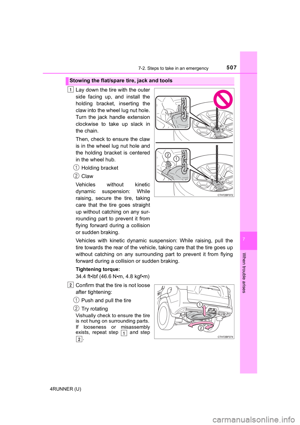
Lay down the tire with the outer
side facing up, and install the
holding bracket, inserting the
claw into the wheel lug nut hole.
Turn the jack handle extension
clockwise to take up slack in
the chain.
Then, check to ensure the claw
is in the wheel lug nut hole and
the holding bracket is centered
in the wheel hub.
Holding bracket
Claw
Vehicles wit hout kinetic
dynamic suspension: While
raising, secure the tire, taking
care that the tire goes straight
up without catching on any sur-
rounding part to prevent it from
flying forward during a collision
or sudden braking.
Vehicles with kinetic dynamic su spension: While raising, pull the
tire towards the rear of the vehi cle, taking care that the tire goes up
without catching on any surrounding part to prevent it from fly ing
forward during a collis ion or sudden braking.
Tightening torque:
34.4 ft•lbf (46.6 N•m, 4.8 kgf•m)
Confirm that the tire is not loose
after tightening: Push and pull the tire
Try rotating
Vishually check to ensure the tire
is not hung on su rrounding parts.
If looseness or misassembly
exists, repeat step and step .
Stowing the flat/spare tire, jack and tools
1
1
2
2
1
2
1
2
Page 508 of 608

5087-2. Steps to take in an emergency
4RUNNER (U)
Repeat step any time the tire is lowered or disturbed.
Stow the tools and jack securely.
■After completing the tire change
The tire pressure warni ng system must be reset. ( P. 430)
■When using the spare tire (veh icles without P245/60R20 tires)
As the spare tire is not equipped with a tire pressure warning valve and
transmitter, low inflation pressure of the spare tire will not be indicated by
the tire pressure warning system. Also, if you replace the spar e tire after
the tire pressure wa rning light comes on, the light remains on.
NOTICE
■Do not drive the vehicle with a flat tire
Do not continue driving with a flat tire.
Driving even a short distance wit h a flat tire can damage the tire and the
wheel beyond repair.
■When stowing the flat tire
Ensure that there is no object c aught between the tire and the vehicle
underbody.
■When replacing the tires
●When removing or fitting the wheels, tires or the tire pressure warning
valve and transmitter, contact your Toyota dealer as the tire p ressure
warning valve and transmitter may be damaged if not handled cor -
rectly.
●Replace the grommets for the tire pressure warning valves and trans-
mitters as well.
■To avoid damage to the tire pressure warning valves and transmi t-
ters
When a tire is repaired with liquid sealants, the tire pressure warning valve and transmitter may not operate properly. If a liquid sea lant is
used, contact your Toyota dealer or other qualified service shop as soon
as possible. Make sure to replace the tire pressure warning valve and
transmitter when replacing the tire. ( P. 430)
32
4
Page 547 of 608

5478-1. Specifications
8
Vehicle specifications
4RUNNER (U)
*:Table 1 Occupant loading and distribution for vehicle normal load for
various designated seating capacities
Section width
The linear distance between the exteriors of
the sidewalls of an inflated tire, excluding ele-
vations due to labeling, decoration, or protec-
tive bands
SidewallThat portion of a tire between the tread and
bead
Sidewall separationThe parting of the rubber compound from the
cord material in the sidewall
Snow tire
A tire that attains a traction index equal to or
greater than 110, compared to the ASTM E-
1136 Standard Reference Test Tire, when
using the snow traction test as described in
ASTM F-1805-00, Standard Test Method for
Single Wheel Driving Traction in a Straight
Line on Snow-and Ice-Covered Surfaces, and
which is marked with an Alpine Symbol ( )
on at least one sidewall
Te s t r i m
The rim on which a tire is fitted for testing, and
may be any rim listed as appropriate for use
with that tire
TreadThat portion of a tire that comes into contact
with the road
Tread ribA tread section running circumferentially
around a tire
Tread separationPulling away of the tread from the tire carcass
Treadwear indicators
(TWI)The projections within the principal grooves
designed to give a visual indication of the
degrees of wear of the tread
Wheel-holding fixtureThe fixture used to hold the wheel and tire
assembly securely during testing
Tire related termMeaning
Page 551 of 608
5518-2. Customization
8
Vehicle specifications
4RUNNER (U)■
Smart key system and wireless remote control
(
P. 106, 113, 124)
■Smart key system (P. 106, 113, 124)
FunctionDefault settingCustomized
setting
Operation signal (buzzer) Level 5 Off
–OO
Level 1 to 7
Operation signal (Emer-
gency flashers) On Off – O O
Time elapsed before the
automatic door lock func-
tion is activated if a door is
not opened after being
unlocked 60 secondsOFF
–OO
30 seconds
120 seconds
Open door warning func-
tion (When locking the
vehicle) On Off – – O
123
FunctionDefault settingCustomized
setting
Smart door unlocking Driver’s door All the doors – O O
Smart key system On Off – – O
Number of consecutive
door lock operations 2 timesAs many
as desired ––O
123
Page 566 of 608
566
4RUNNER (U)
●Déroulez la sangle diagonale
de telle sorte qu’elle passe bien
sur l’épaule, sans pour autant
être en contact avec le cou ou
glisser de l’épaule.
● Placez la sangle abdominale le
plus bas possible sur les
hanches.
● Réglez la position du dossier de s iège. Asseyez-vous le dos le plus
droit possible et calez-vous bien dans le siège.
● Ne vrillez pas la cei nture de sécurité.
■Ceintures de sécurité
Nettoyez avec un chiffon ou une éponge humectée d’eau savon-
neuse tiède. Vérifiez régulièrement que les ceintures ne sont p as
effilochées, entaillées ou exagérément usées.
Seat belt instructions for Canadian owners
(in French)
The following is a French explan ation of seat belt instructions
extracted from the seat bel t section in this manual.
See the seat belt section for mo re detailed seat belt instructions in
English.
Utilisation correcte d es ceintures de sécurité
Entretien et soin
Page 567 of 608
567
9
For owners
4RUNNER (U)
WARNING
■Détérioration et usure des ceintures de sécurité
Inspectez les ceintures de sécurité périodiquement. Contrôlez q u’elles ne
sont pas entaillées, effilochées et que leurs ancrages ne sont pas desser-
rés. N’utilisez pas une ceinture de sécurité défectueuse avant qu’elle ne soit
remplacée. Une ceinture de sécurité défectueuse n’apporte aucune garan-
tie de protection de l’occupant en cas d’accident.
Page 570 of 608
570
4RUNNER (U)
Composition du système de coussins gonflables SRS
Coussins gonflables latéraux
Témoins indicateurs “AIR
BAG ON” et “AIR BAG OFF”
Coussins gonfl ables rideaux
Coussin gonflable passager
avant
Coussins gonflables de
genoux
Capteurs d’impact latéral
(porte avant)
Prétensionneurs de ceintures
de sécurité et limiteurs de
force
Capteurs d’impact avant
Capteur de coussin gonflable Commutateur de boucle de
ceinture de sécurité du siège
du passager avant
Système de classification de
l’occupant du siège passager
avant (ECU et capteurs)
Capteurs d’impact latéral
(arrière)
Témoin d’avert
issement SRS
Capteur de protection (arrière)
Coussin gonflable conducteur
Commutateur de boucle de
ceinture de sécurité du
conducteur1
2
3
4
5
6
7
8
9
10
11
12
13
14
15
16