2023 SUBARU SOLTERRA roof rack
[x] Cancel search: roof rackPage 36 of 628

361-1. For safe use
Owners Manual_USA_M42C01_en
Front passenger occupant classification sensors
SRS warning light
Airbag sensor assembly
Your vehicle is equipped with ADVANCED AIRBAGS designed
based on the US motor vehicle safety standards (FMVSS208). The
airbag sensor assembly (ECU) cont rols airbag deployment based on
information obtained from the sensors etc. shown in the system
components diagram above. This in formation includes crash sever-
ity and occupant information. As the airbags deploy, a chemical
reaction in the inflators quickly fills the airbags with non-toxic gas to
help restrain the motion of the occupants.
■If the SRS airbags deploy
(inflate)
●Slight abrasions, burns, bruising
etc., may be sustained from SRS
airbags, due to the extremely high
speed deployment (inflation) by
hot gases.
●A loud noise and white powder will
be emitted.
●Parts of the airbag module (steer-
ing wheel hub, airbag cover and
inflator) as well as the front seats,
parts of the front and rear pillars,
and roof side rails, may be hot for
several minutes. T he airbag itself
may also be hot.
●The windshield may crack.
●The EV system will be stopped.
( P. 8 0 )
●All of the doors will be unlocked.
( P.168)
●The brakes and st op lights will be
controlled automatically. ( P.388)
●The interior lights will turn on auto-
matically. ( P.416)
●The emergency flashers will turn
on automatically. ( P.504)
●For Safety Connect subscribers, if
any of the following situations
occur, the system is designed to
send an emergency call to the
response center, notifying them of the vehicle’s location (without
needing to push the “SOS” button)
and an agent will attempt to speak
with the occupants to ascertain
the level of emergency and assis-
tance required. If the occupants
are unable to communicate, the
agent automatically treats the call
as an emergency and helps to dis-
patch the necessary emergency
services. (
P. 6 4 )
• An SRS airbag is deployed.
• A seat belt pretensioner is acti- vated.
• The vehicle is involved in a severe rear-end collision.
■SRS airbag deployment condi-
tions (SRS front airbags)
●The SRS front airbags will deploy
in the event of an impact that
exceeds the set threshold level
(the level of forc e corresponding
to an approximately 12 - 18 mph
[20 - 30 km/h] frontal collision with
a fixed wall that does not move or
deform).
However, this threshold velocity will
be considerably higher in the follow-
ing situations:
• If the vehicle strikes an object, such as a parked vehicle or sign
pole, which can move or deform
on impact
• If the vehicle is involved in an underride collision, such as a colli-
Page 39 of 628

391-1. For safe use
Owners Manual_USA_M42C01_en
1
For safety and security
●The pad section of the steering
wheel, dashboard near the front
passenger airbag o r lower portion
of the instrument panel is
scratched, cracked, or otherwise
damaged.
●The surface of the seats with the
SRS side airbag is scratched,
cracked, or otherwise damaged.
●The portion of the front pillars, rear
pillars or roof side rail garnishes
(padding) containing the SRS cur-
tain shield airbags inside, is
scratched, cracked, or otherwise
damaged.
WARNING
■SRS airbag precautions
Observe the following precautions
regarding the SRS airbags.
Failure to do so may cause death
or serious injury.
●The driver and all passengers in
the vehicle must wear their seat
belts properly.
The SRS airbags are supple-
mental devices to be used with
the seat belts.
●The SRS driver airbag deploys
with considerable force, and
can cause death or serious
injury especially if the driver is
very close to the airbag. The
National Highway Traffic Safety
Administration (NHTSA)
advises:
Since the risk zone for the driver’s
airbag is the first 2 - 3 in. (50 - 75
mm) of inflation, placing yourself
10 in. (250 mm) from your driver
airbag provides you with a clear
margin of safety. This distance is
measured from the center of the
steering wheel to your breast-
bone. If you sit less than 10 in.
(250 mm) away now, you can
change your driving position in
several ways:
• Move your seat to the rear as far as you can while still reach-
ing the pedals comfortably.
Page 42 of 628

421-1. For safe use
Owners Manual_USA_M42C01_en
WARNING
●Do not hang coat hangers or
other hard objects on the coat
hooks. All of these items could
become projectiles and may
cause death or serious injury,
should the SRS curtain shield
airbags deploy.
●If a vinyl cover is put on the area
where the SRS knee airbag will
deploy, be sure to remove it.
●Do not use seat accessories
which cover the parts where the
SRS side airbags inflate as they
may interfere with inflation of
the SRS airbags. Such acces-
sories may prevent the SRS
side airbags from activating cor-
rectly, disable the system or
cause the SRS side airbags to
inflate accidentally, resulting in
death or serious injury.
●Do not strike or apply significant
levels of force to the area of the
SRS airbag components or the
front doors.
Doing so can cause the SRS
airbags to malfunction.
●Do not touch any of the compo-
nent parts immediately after the
SRS airbags have deployed
(inflated) as they may be hot.
●If breathing becomes difficult
after the SRS airbags have
deployed, open a door or win-
dow to allow fresh air in, or
leave the vehicle if it is safe to
do so. Wash off any residue as
soon as possible to prevent skin
irritation.
●If the areas where the SRS air-
bags are stored, such as the
steering wheel pad and front
and rear pillar ga rnishes, are
damaged or cracked, have
them replaced by your Toyota
dealer.
●Do not place anything, such as
a cushion, on the front passen-
ger’s seat. Doing so will
disperse the passenger’s
weight, which prevents the sen-
sor from detecting the passen-
ger’s weight properly. As a
result, the SRS front airbags for
the front passenger may not
deploy in the event of a colli-
sion.
■Modification and disposal of
SRS airbag system compo-
nents
Do not dispose of your vehicle or
perform any of the following modi-
fications without consulting your
Toyota dealer. The SRS airbags
may malfunction or deploy
(inflate) accidentally, causing
death or serious injury.
●Installation, re moval, disassem-
bly and repair of the SRS air-
bags
●Repairs, modific ations, removal
or replacement of the steering
wheel, instrument panel, dash-
board, seats or seat upholstery,
front, side and rear pillars, roof
side rails, front door panels,
front door trims or front door
speakers
●Modifications to the front door
panel (such as making a hole in
it)
●Repairs or modifications of the
front fender, front bumper, or
side of the occupant compart-
ment
●Installation of a grille guard (bull
bars, kangaroo bar, etc.), snow
plows, winches or roof luggage
carrier
●Modifications to the vehicle’s
suspension system
Page 262 of 628

2625-4. Using the driving support systems
Owners Manual_USA_M42C01_en
WARNING
●Always keep the windshield
clean.
• If the windshield is dirty or cov- ered with an o ily film, water
droplets, snow, etc., clean the
windshield.
• Even if a glass coating agent is applied to the windshield, it will
still be necessary to use the
windshield wipers to remove
water droplets, etc. from the
area of the windshield in front of
the front camera.
• If the inner side of the wind- shield where the front camera is
installed is dirty, contact your
Toyota dealer
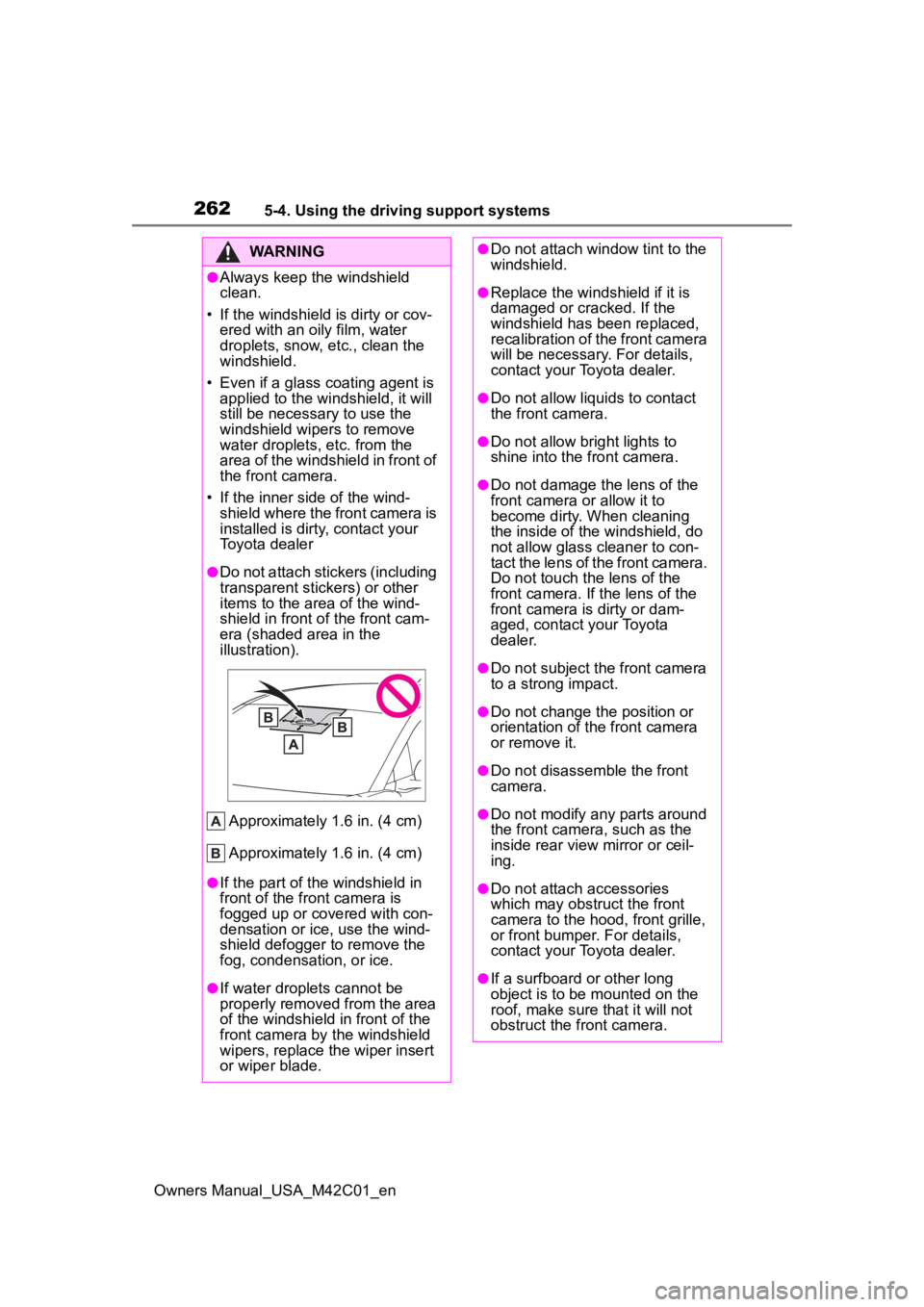
●Do not attach stickers (including
transparent stickers) or other
items to the area of the wind-
shield in front o f the front cam-
era (shaded area in the
illustration).
Approximately 1.6 in. (4 cm)
Approximately 1.6 in. (4 cm)
●If the part of the windshield in
front of the front camera is
fogged up or covered with con-
densation or ice, use the wind-
shield defogger to remove the
fog, condensation, or ice.
●If water droplets cannot be
properly removed from the area
of the windshield in front of the
front camera by the windshield
wipers, replace the wiper insert
or wiper blade.
●Do not attach window tint to the
windshield.
●Replace the windshield if it is
damaged or cracked. If the
windshield has been replaced,
recalibration of the front camera
will be necessary. For details,
contact your Toyota dealer.
●Do not allow liquids to contact
the front camera.
●Do not allow bright lights to
shine into the front camera.
●Do not damage th e lens of the
front camera o r allow it to
become dirty. When cleaning
the inside of the windshield, do
not allow glass cleaner to con-
tact the lens of the front camera.
Do not touch the lens of the
front camera. If the lens of the
front camera is dirty or dam-
aged, contact your Toyota
dealer.
●Do not subject the front camera
to a strong impact.
●Do not change the position or
orientation of the front camera
or remove it.
●Do not disassemble the front
camera.
●Do not modify any parts around
the front camera , such as the
inside rear view mirror or ceil-
ing.
●Do not attach accessories
which may obstruct the front
camera to the hood, front grille,
or front bumper. For details,
contact your Toyota dealer.
●If a surfboard or other long
object is to be mounted on the
roof, make sure that it will not
obstruct the front camera.
Page 536 of 628

5368-2. Steps to take in an emergency
Owners Manual_USA_M42C01_en
WARNING
●Connect the valve and hose
securely with the tire installed
on the vehicle.
If the hose is not properly con-
nected to the valve, air leakage
may occur as sealant may be
sprayed out.
●If the hose comes off the valve
while inflating the tire, there is a
risk that the hose will move
abruptly due to air pressure.
●After inflation of the tire has
completed, the sealant may
splatter when the hose is dis-
connected or some air is let out
of the tire.
●Follow the operation procedure
to repair the tire. If the proce-
dure is not followed, the sealant
may spray out.
●Keep back from the tire while it
is being repaired, as there is a
chance of it bursting while the
repair operation is being per-
formed. If you notice any cracks
or deformation of the tire, turn
off the compressor switch and
stop the repair operation imme-
diately.
●The repair kit may overheat if
operated for a long period of
time. Do not operate the com-
pressor continuously for more
than 40 minutes.
●Parts of the repair kit become
hot during operation. Be careful
handling the repair kit during
and after operation. Do not
touch the metal part connecting
the bottle and the compressor. It
will be extremely hot.
●Do not attach the vehicle speed
warning sticker to an area other
than the one indicated. If the
sticker is attached to an area
where an SRS airbag is located,
such as the pad of the steering
wheel, it may prevent the SRS
air bag from operating properly.
■Driving to spread the liquid
sealant evenly
Observe the following precautions
to reduce the risk of accidents.
Failing to do so may result in a
loss of vehicle control and cause
death or serious injury.
●Drive the vehicle carefully at a
low speed. Be especially careful
when turning and cornering.
●If the vehicle does not drive
straight or you feel a pull
through the steering wheel, stop
the vehicle and check the fol-
lowing:
• Tire condition. The tire may have separated from the wheel.
• Tire inflation pressure. If the tire inflation pressure is 19 psi (130
kPa, 1.3 kgf/cm
2 or bar) or less,
the tire may be severely dam-
aged.
NOTICE
■When performing an emer-
gency repair
●Perform the emergency repair
without removing the nail or
screw that has punctured the
tread of the tire. If the object
that has punctur ed the tire is
removed, repair by the emer-
gency tire puncture repair kit
may not be possible.
●The repair kit is not waterproof.
Make sure that the repair kit is
not exposed to water, such as
when it is being used in the rain.
Page 561 of 628

5619-1. Specifications
Owners Manual_USA_M42C01_en
9
Vehicle specifications
Production options weight
The combined weight of installed regular pro-
duction options weighing over 5 lb. (2.3 kg) in
excess of the standard items which they
replace, not previously considered in curb
weight or accessory weight, including heavy
duty brakes, ride leveler s, roof rack, heavy duty
battery, and special trim
RimA metal support for a ti re or a tire and tube
assembly upon which the tire beads are seated
Rim diameter
(Wheel diameter)Nominal diameter o f the bead seat
Rim size designationRim diameter and width
Rim type designationThe industry manufacture r’s designation for a
rim by style or code
Rim widthNominal distance between rim flanges
Vehicle capacity weight
(Total load capacity)The rated cargo and luggage load plus 150 lb.
(68 kg) times the vehicl e’s designated seating
capacity
Vehicle maximum load on
the tireThe load on an individual tire that is determined
by distributing to each ax le its share of the max-
imum loaded vehicle weight, and dividing by two
Vehicle normal load on
the tire
The load on an individual tire that is determined
by distributing to each axle its share of curb
weight, accessory weight, and normal occupant
weight (distributed in accordance with Table 1
*
below), and dividing by two
Weather sideThe surface area of the rim not covered by the
inflated tire
Bead
The part of the tire that is made of steel wires,
wrapped or reinforced by ply cords and that is
shaped to fit the rim
Bead separationA breakdown of the bond between components
in the bead
Bias ply tire
A pneumatic tire in which the ply cords that
extend to the beads are la id at alternate angles
substantially less than 9 0 degrees to the center-
line of the tread
Tire related termMeaning