Page 172 of 348

170
Driving
Malfunction
In the event of a malfunction when
changing into reverse gear, this warning
lamp lights up on the instrument panel,
accompanied by the display of a message and
an audible signal (short beep).
Have it checked by a PEUGEOT dealer or a
qualified workshop.
Visiopark 1
For more information, refer to the
General recommendations on the use
of driving and manoeuvring aids .
As soon as reverse gear is engaged with the
engine running, this system displays views of
your vehicle’s close surroundings on the touch
screen using a camera located at the rear of the
vehicle.
The screen is divided into two parts with a
contextual view and a view from above the
vehicle in its close surroundings.
The parking sensors supplement the information
on the view from above the vehicle.
Various contextual views may be displayed:
–
Standard view
.
–
180° view
.
–
Zoom view
.
AUTO mode is activated by default.
In this mode, the system chooses the best view
to display
(standard or zoom).
You can change the type of view at any time
during a manoeuvre.
The system status is not saved when the ignition
is switched off.
Principle of operation
Using the rear camera, the vehicle's close
surroundings are recorded during manoeuvres
at low speed.
An image from above your vehicle in its close
surroundings is reconstructed (represented
between the brackets) in real time and as the
manoeuvre progresses.
It facilitates the alignment of your vehicle when
parking and allows obstacles close to the vehicle
to be seen. It is automatically deleted if the
vehicle remains stationary for too long.
The display disappears above approximately 6 mph (10 km/h).
The system is automatically deactivated
about 7 seconds after coming out of reverse
or on opening a door or the boot.
Activation
Activation is automatic on engaging reverse gear
at a speed lower than 6 mph (10 km/h).
CarM an uals 2 .c o m
Page 176 of 348

174
Practical information
Compatibility of fuels
Diesel fuels conforming to the EN590, EN16734
and EN16709 standards and containing up to
7%, 10%, 20% and 30% fatty acid methyl ester
respectively. The use of B20 or B30 fuels, even
occasionally, imposes special maintenance
conditions referred to as "Arduous conditions".
Paraffinic Diesel fuel conforming to the EN15940
standard.
The use of any other type of (bio) fuel (e.g. pure or diluted vegetable or animal
oils, domestic fuel) is strictly prohibited - risk
of damaging the engine and fuel system!
The only Diesel fuel additives authorised for use are those that meet the B715000
standard.
Diesel at low temperature
At temperatures below 0 °C (+32 °F), the
formation of paraffins in summer-type Diesel
fuels could prevent the engine from operating
correctly
. In these temperature conditions, use
winter-type Diesel fuel and keep the fuel tank
more than 50
% full.
At temperatures below -15 °C (+5 °F) to avoid
problems starting, it is best to park the vehicle
under shelter (heated garage).
Travelling abroad
Certain fuels could damage your vehicle’s
engine.
In certain countries, the use of a particular
fuel may be required (specific octane rating,
specific trade name, etc.) to ensure correct
operation of the engine.
For all additional information, consult a dealer.
Refuelling
Fuel tank capacity: approximately 69 litres.
Reserve level: approximately 6 litres.
Low fuel level
When the low fuel level is reached,
one of these warning lamps lights
up on the instrument panel, accompanied by the
display of a message and an audible signal.
When it first comes on, about 8 litres of fuel
remain.
You must refuel as soon as possible to avoid
running out of fuel.
For more information on Running out of fuel
(Diesel), refer to the corresponding section.
A small arrow by the warning lamp indicates which side of the vehicle the
fuel filler flap is located on.
Stop & Start
Never refuel with the engine in STOP
mode; you must switch off the ignition.
Refuelling
At least 8 litres of fuel must be added, in order to
be registered by the fuel gauge.
Opening the filler cap may create a noise caused
by an inrush of air. This is entirely normal and
results from the sealing of the fuel system.
To refuel in complete safety:
►
Always switch off the engine.
►
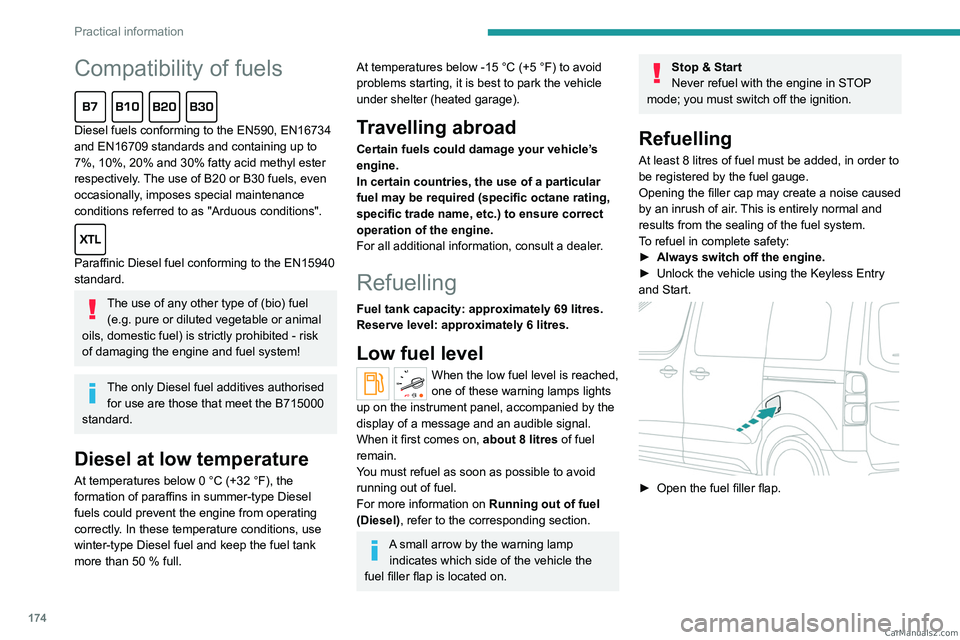
Unlock the vehicle using the Keyless Entry
and Start.
► Open the fuel filler flap. CarM an uals 2 .c o m
Page 211 of 348

209
In the event of a breakdown
8► Progressively return the wheel to the carrier
by pushing alternately at the left and right until it
is clear of the hook fixing area.
►
Engage the carrier on the hook, then tighten
the bolt using the wheelbrace
until the bolt is fully
tightened.
Tyre in the carrier
You can change the size of the tyre on the spare
wheel by following the instructions below.
Original
tyre size Standard Long
215/65 R16 Placing a 225 wheel in the carrier is prohibited. There is no
restriction.
215/60 R17
215/60 R17
M&S
225/55 R17 Placing a 215 wheel in the
carrier is not
recommended (risk of noise).
A punctured tyre of size 215 or 225 can be placed in the carrier.
Removing a wheel
Parking the vehicle
Immobilise the vehicle where it does
not obstruct traffic: the ground must be level,
stable and non-slippery.
With a manual gearbox, engage first gear
then switch off the ignition to block the
wheels.
With an automatic gearbox, place the gear
selector in position P then switch off the
ignition to block the wheels.
With a drive selector, place the gear selector
in position P then switch off the ignition to
block the wheels.
Apply the parking brake, unless it is
programmed to automatic mode (for an
electric parking brake), and check that the
indicator lamp lights up on
the instrument
panel.
Ensure that the occupants have left the
vehicle and are located in a safe place.
Never go underneath a vehicle raised using a
jack; use an axle stand.
With an electric parking brake, place a chock
against the wheel diagonally opposite to the
one being replaced.
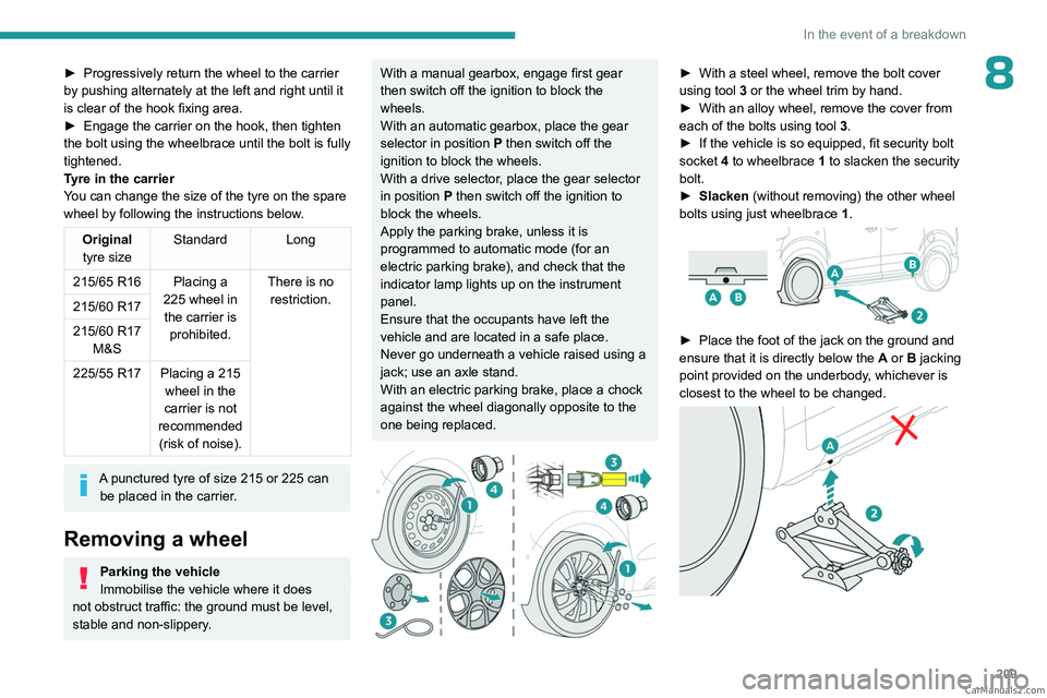
► With a steel wheel, remove the bolt cover
using tool 3
or the wheel trim by hand.
►
With an alloy wheel, remove the cover from
each of the bolts using tool 3
.
►
If the vehicle is so equipped, fit security bolt
socket
4 to wheelbrace 1 to slacken the security
bolt.
►
Slacken
(without removing) the other wheel
bolts using just wheelbrace 1.
► Place the foot of the jack on the ground and
ensure that it is directly below the A
or B jacking
point provided on the underbody, whichever is
closest to the wheel to be changed.
CarM an uals 2 .c o m
Page 302 of 348
10 Instruments and controls
Instruments and
controls
Warning lights, gauges and indi‐ cators ........................................... 10
Instrument cluster ......................10
Hydrogen gauge ........................10
Hydrogen leakage .....................11
Fuel cell system fault .................11
Displays ....................................... 11
Driver Information Centre ..........11 Warning lights, gauges
and indicators
Instrument cluster Overview
u
Hydrogen leakage 3 11
v Fuel cell system fault 3 11
w 2 Low hydrogen level 3
10 Hydrogen gauge
Displays the hydrogen level in the
tank.
If the control indicator 2 illuminates
yellow, refuel the tank immediately.
If
additionally the charging level of the
high voltage battery is too low, M
illuminates yellow.
Refueling 3 15.
Charging 3 14.CarM an uals 2 .c o m
Page 315 of 348
Vehicle care 23
3. Allow both engines to idle for approx. three minutes with the
leads connected.
4.
Switch on electrical consumers
e.g. headlights, heated rear
window of the vehicle receiving
the jump start.
5. Reverse above sequence exactly when removing leads.CarM an uals 2 .c o m
Page:
< prev 1-8 9-16 17-24