2023 PEUGEOT 3008 height
[x] Cancel search: heightPage 106 of 292

104
Safety
the vehicle, so as to avoid the seat interfering
with the operation of the seat belt.
An incorrectly installed child seat in a vehicle compromises the child's safety in
the event of an accident.
Strictly observe the fitting instructions
provided in the user guide supplied with the
child seat.
For information about the options for
fitting ISOFIX child seats in your vehicle,
refer to the summary table.
Recommended ISOFIX child
seats
Also consult the user guide from the child seat’s manufacturer to find out how to
install and remove the seat.
"RÖMER Baby-Safe and its ISOFIX base" (size category: E)
Group 0+: from birth to 13 kg
"RÖMER Baby-Safe and its ISOFIX base" (size category: E)
Group 0+: from birth to 13 kg
Installed "rearward facing" using an ISOFIX base which is attached to rings
A
.
The base has a support leg, height-
adjustable, which rests on the vehicle's floor. This child seat can also be secured with a
seat belt. In this case, only the shell is used and attached to the vehicle seat using the three-point seat belt.
"RÖMER Duo Plus ISOFIX "
(size category: B1)
Group 1: from 9 to 18 kg
"RÖMER Duo Plus ISOFIX "
(size category: B1)
Group 1: from 9 to 18 kg
Suitable for forward-facing installation only.
Attached to rings
A and ring B, referred to as
TOP TETHER, using an upper strap.
Three seat body angles: sitting, reclining, lying down.
This child seat can also be used in seat positions not equipped with ISOFIX
mountings. In this case, it must be secured to the vehicle's seat by the three-point seat belt. Adjust the front seat of the vehicle so that the child's feet do not touch the backrest. CarM an uals 2 .c o m
Page 107 of 292
105
Safety
5Locations for ISOFIX child seats
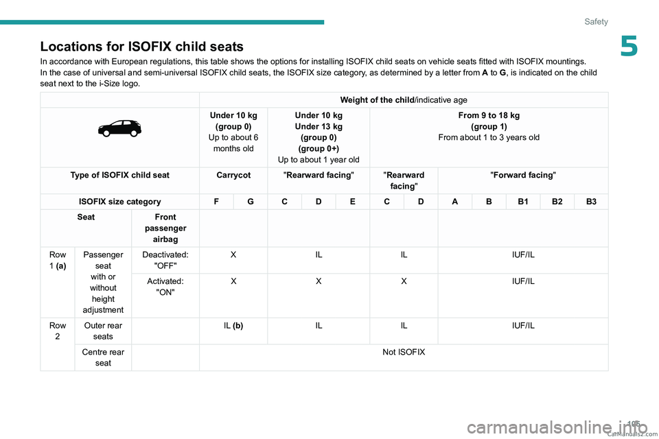
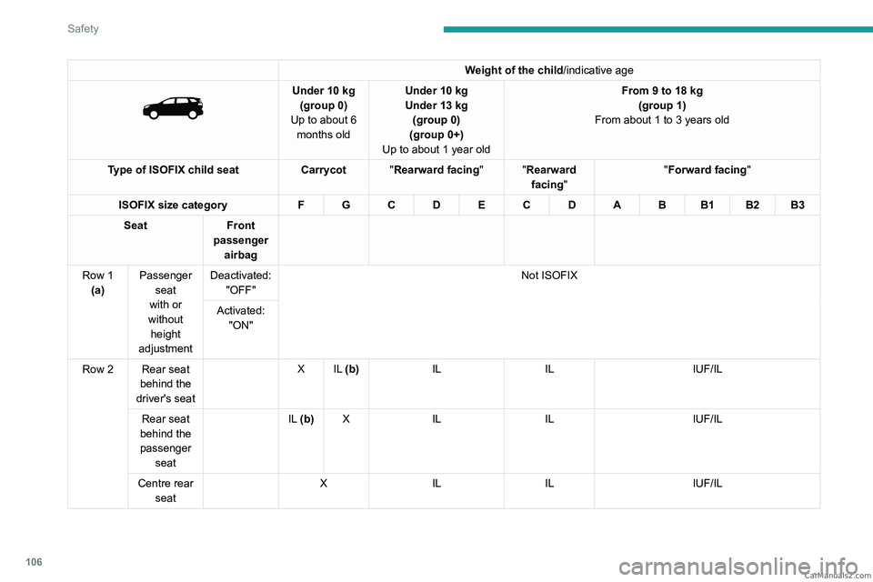
In accordance with European regulations, this table shows the options for installing ISOFIX child seats on vehicle seats fitted with ISOFIX mountings.
In the case of universal and semi-universal ISOFIX child seats, the ISOF\
IX size category, as determined by a letter from A to G, is indicated on the child
seat next to the i-Size logo.
Weight of the child/indicative age
Under 10 kg
(group 0)
Up to about 6 months old Under 10
kg
Under 13 kg
(group 0)
(group 0+)
Up to about 1 year old From 9 to 18
kg
(group 1)
From about 1 to 3 years old
Type of ISOFIX child seat Carrycot"Rearward facing" "Rearward
facing""Forward facing
"
ISOFIX size category F G C D E C D A B B1 B2 B3
Seat Front
passenger airbag
Row
1 (a) Passenger
seat
with or
without height
adjustment Deactivated:
"OFF" X
IL IL IUF/IL
Activated: "ON" X
XX IUF/IL
Row 2 Outer rear
seats IL (b)
ILIL IUF/IL
Centre rear seat Not ISOFIX CarM an uals 2 .c o m
Page 108 of 292
106
Safety
Weight of the child/indicative age
Under 10 kg
(group 0)
Up to about 6 months old Under 10
kg
Under 13 kg
(group 0)
(group 0+)
Up to about 1 year old From 9 to 18
kg
(group 1)
From about 1 to 3 years old
Type of ISOFIX child seat Carrycot"Rearward facing" "Rearward
facing""Forward facing
"
ISOFIX size category F G C D E C D A B B1 B2 B3
Seat Front
passenger airbag
Row 1 (a) Passenger
seat
with or
without height
adjustment Deactivated:
"OFF" Not ISOFIX
Activated: "ON"
Row 2 Rear seat behind the
driver's seat X
IL (b) IL IL IUF/IL
Rear seat
behind the
passenger seat IL (b)
X IL IL IUF/IL
Centre rear seat X
IL IL IUF/IL CarM an uals 2 .c o m
Page 110 of 292
108
Safety
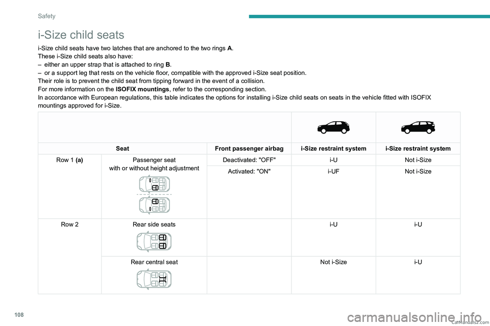
i-Size child seats
i-Size child seats have two latches that are anchored to the two rings A.
These i-Size child seats also have:
–
either an upper strap that is attached to ring B
.
–
or a support leg that rests on the vehicle floor
, compatible with the approved i-Size seat position.
Their role is to prevent the child seat from tipping forward in the even\
t of a collision.
For more information on the ISOFIX mountings, refer to the corresponding section.
In accordance with European regulations, this table indicates the options for installing i-Size child seats on seats in the vehicle fitted with ISOFIX
mountings approved for i-Size.
Seat
Front passenger airbag i-Size restraint system i-Size restraint system
Row 1 (a) Passenger seat
with or without height adjustment
Deactivated: "OFF" i-UNot i-Size
Activated: "ON" i-UFNot i-Size
Row 2 Rear side seats
i-U i-U
Rear central seat
Not i-Size i-U CarM an uals 2 .c o m
Page 114 of 292

11 2
Driving
Towing
Driving with a trailer places greater
demands on the towing vehicle and
particular care must be taken.
Do not exceed the maximum towable
weights.
At altitude: reduce the maximum load by
10% per 1,000 metres of altitude; the lower
air density at high altitudes decreases engine
performance.
New vehicle: do not tow a trailer until the
vehicle has driven at least 620 miles
(1,000 kilometres).
If the outside temperature is high, let the
engine idle for 1 to 2 minutes after the
vehicle comes to a stop, to help it to cool.
Before setting off
Nose weight
► Distribute the load in the trailer so that the
heaviest items are located as close as possible
to the axle, and the nose weight (at the point
where it joins your vehicle) approaches the
maximum permitted, without exceeding it.
Tyres
► Check the tyre pressures of the towing
vehicle and of the trailer , observing the
recommended pressures.
Lighting
► Check the electrical signalling on the trailer
and the headlamp beam height of your vehicle.
If a genuine PEUGEOT towing device is
used, the rear parking sensors will be
deactivated automatically to avoid activating
the audible signal.
When driving
Cooling
Towing a trailer uphill causes the coolant
temperature to increase. The maximum towable
load depends on the gradient and the exterior
temperature. The fan’s cooling capacity does not
increase with engine speed.
►
Reduce speed and lower the engine speed to
limit the amount of heating produced.
►
Pay constant attention to the coolant
temperature.
If this warning lamp and the STOP
warning lamp come on, stop the
vehicle and switch off the engine as soon as
possible.
Brakes
Using the engine brake is recommended to limit
the overheating of the brakes. Braking distances
are increased when towing a trailer.
Side wind
Bear in mind that the vehicle will be more
susceptible to wind when towing.
Anti-theft protection
Electronic immobiliser
The keys contain a code, which must be
recognised by the vehicle before starting is
possible.
If the system malfunctions, indicated by the
display of a message, the engine will not start.
Contact a PEUGEOT dealer.
Starting/Switching off the
engine
The electronic key must be present in the passenger compartment.
If the electronic key is not detected, a
message is displayed.
Move the electronic key so that the engine
can be started or switched off.
If there is still a problem, refer to the "Key
not detected - Back-up starting or Back-up
switch-off" section. CarM an uals 2 .c o m
Page 153 of 292
151
Driving
6Deactivation/Activation
By default, the system is automatically activated
at every engine start.
The settings are changed via the Driving/Vehicle touch screen menu.
Deactivation of the system is signalled by
the illumination of this warning lamp,
accompanied by the display of a message.
Operating conditions and
limits
Vehicle moving forward without trailer.
Brake system operational.
DSC/ASR systems activated.
Seat belts fastened for all passengers.
Stabilised speed on roads with no or low
curvature.
This warning lamp lights up on the instrument panel without any additional
message, to indicate that the automatic braking
system is not available.
This is a normal behavior indicating that a
condition is not fulfilled and which does not
request the support of a workshop.
In any situations with ignition on where automatic
braking presents a risk, deactivating the
system via the vehicle's configuration menu is
recommended, for instance:
–
T
owing a trailer (particularly a trailer without its
own braking system).
–
Carrying long objects on roof bars.
–
Driving with snow chains.
– Using an automatic car wash.
– Performing any maintenance (e.g. changing a
wheel, working inside the engine compartment).
–
Placing the vehicle on a rolling bench in a
workshop.
–
T
owing the vehicle.
–
Following a front bumper deformation (version
with radar).
–
Following
an impact to the windscreen close to
the detection camera.
The system is automatically deactivated once the use of a different diameter
"space-saver" type spare wheel is detected,
or if a fault with the two lateral brake lamps is
detected.
The system diagnoses permanently its capability and may inhibit itself without
specific driver indication, if the system is
outside of the regular operating conditions
(e.g.
sensor initialization, board voltage out of
regular range, activation of stability system).
Therefore, the system may not be available
just after starting the vehicle.
It can be dangerous to drive if the brake
lamps are not in perfect working order.
The driver must not overload the vehicle (keep within the GVW limit and load
height limits for roof bars).
Following an impact (e.g. a collision), the
system is automatically deactivated.
Have it checked by a PEUGEOT dealer or a
qualified workshop.
Collision Risk Alert
This function warns the driver if there is a risk
of collision with the preceding vehicle, or with a
pedestrian or cyclist.
Modifying the alert trigger threshold
This trigger threshold determines the sensitivity
with which the function warns of the risk of
collision.
The threshold is set via the Driving/Vehicle touch screen menu.
►
Select one of the three pre-defined
thresholds: "
Far", "Normal" or "Close".
The last threshold selected is memorised when
the ignition is switched off.
Operation
Depending on the collision risk detected by the
system and the alert trigger threshold chosen
by the driver, different levels of alert may be
triggered and displayed on the instrument panel.
The system takes into account the vehicle
dynamics, the difference speed of the own
vehicle and the object identified for the
collision risk, and the operation of the vehicle
(e.g.
actions on the pedals, steering wheel) to
trigger the alert at the most relevant moment. CarM an uals 2 .c o m
Page 181 of 292
179
Practical information
7Before each use
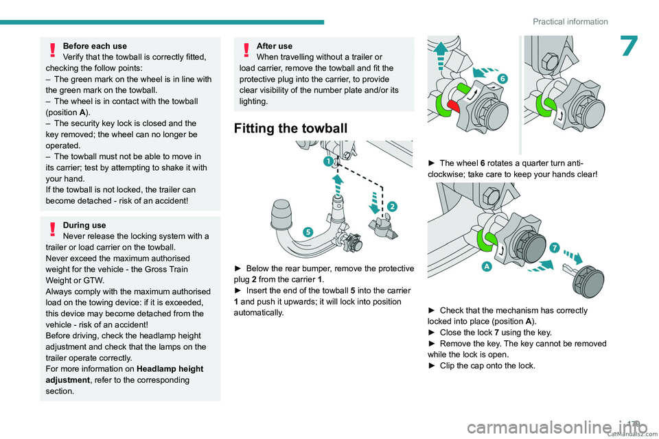
Verify that the towball is correctly fitted,
checking the follow points:
–
The green mark on the wheel is in line with
the green mark on the towball.
–
The wheel is in contact with the towball
(position A
).
–
The security key lock is closed and the
key removed; the wheel can no longer be
operated.
–
The towball must not be able to move in
its carrier; test by attempting to shake it with
your hand.
If the towball is not locked, the trailer can
become detached - risk of an accident!
During use
Never release the locking system with a
trailer or load carrier on the towball.
Never exceed the maximum authorised
weight for the vehicle - the Gross Train
Weight or GTW.
Always comply with the maximum authorised
load on the towing device: if it is exceeded,
this device may become detached from the
vehicle - risk of an accident!
Before driving, check the headlamp height
adjustment and check that the lamps on the
trailer operate correctly.
For more information on Headlamp height
adjustment, refer to the corresponding
section.
After use
When travelling without a trailer or
load carrier, remove the towball and fit the
protective plug into the carrier, to provide
clear visibility of the number plate and/or its
lighting.
Fitting the towball
► Below the rear bumper , remove the protective
plug 2 from the carrier 1.
►
Insert the end of the towball
5 into the carrier
1 and push it upwards; it will lock into position
automatically.
► The wheel 6 rotates a quarter turn anti-
clockwise; take care to keep your hands clear!
► Check that the mechanism has correctly
locked into place (position A
).
►
Close the lock 7
using the key.
►
Remove the key
. The key cannot be removed
while the lock is open.
►
Clip the cap onto the lock. CarM an uals 2 .c o m
Page 183 of 292
181
Practical information
7transverse roof bars approved for your
vehicle.
Observe the instructions on fitting and use
contained in the guide supplied with the roof
bars.
Maximum load distributed over the
transverse roof bars, for a loading height
not exceeding 40 cm (except bicycle carrier):
80
kg.
As this value may change, please verify the
maximum load quoted in the guide supplied
with the roof bars.
If the height exceeds 40 cm, adapt the speed
of the vehicle to the profile of the road to
avoid damaging the roof bars and the fixings
on the vehicle.
Be sure to refer to national legislation in order
to comply with the regulations for transporting
objects that are longer than the vehicle.
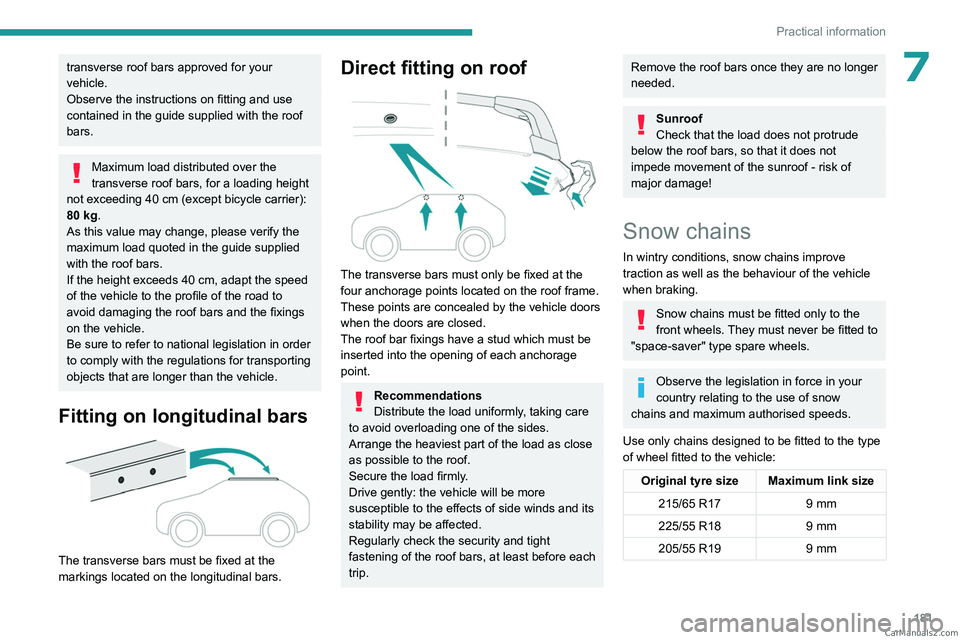
Fitting on longitudinal bars
The transverse bars must be fixed at the
markings located on the longitudinal bars.
Direct fitting on roof
The transverse bars must only be fixed at the
four anchorage points located on the roof frame.
These points are concealed by the vehicle doors
when the doors are closed.
The roof bar fixings have a stud which must be
inserted into the opening of each anchorage
point.
Recommendations
Distribute the load uniformly, taking care
to avoid overloading one of the sides.
Arrange the heaviest part of the load as close
as possible to the roof.
Secure the load firmly.
Drive gently: the vehicle will be more
susceptible to the effects of side winds and its
stability may be affected.
Regularly check the security and tight
fastening of the roof bars, at least before each
trip.
Remove the roof bars once they are no longer
needed.
Sunroof
Check that the load does not protrude
below the roof bars, so that it does not
impede movement of the sunroof - risk of
major damage!
Snow chains
In wintry conditions, snow chains improve
traction as well as the behaviour of the vehicle
when braking.
Snow chains must be fitted only to the
front wheels. They must never be fitted to
"space-saver" type spare wheels.
Observe the legislation in force in your
country relating to the use of snow
chains and maximum authorised speeds.
Use only chains designed to be fitted to the type
of wheel fitted to the vehicle:
Original tyre size Maximum link size 215/65 R17 9 mm
225/55 R18 9 mm
205/55 R19 9 mm CarM an uals 2 .c o m