2023 NISSAN SENTRA gas type
[x] Cancel search: gas typePage 186 of 556

FUEL-FILLER CAP
WARNING
• Gasoline is extremely flammable and
highly explosive under certain condi-
tions. You could be burned or seri-
ously injured if it is misused or mis-
handled. Always stop the engine and
do not smoke or allow open flames or
sparks near the vehicle when
refueling.
• Do not attempt to top off the fuel
tank af ter the fuel pump nozzle
shuts off automatically. Continued
refueling may cause fuel overflow,
resulting in fuel spray and possibly a
fire.
• Use only an original equipment type
fuel-filler cap as a replacement. It has
a built-in safety valve needed for
proper operation of the fuel system
and emission control system. An in-
correct cap can result in a serious
malfunction and possible injury. It
could also cause the
Malfunc-
tion Indicator Light (MIL) to come on.
• Never pour fuel into the throttle body
to attempt to start your vehicle. •
Do not fill a portable fuel container in
the vehicle or trailer. Static electricity
can cause an explosion of flammable
liquid, vapor or gas in any vehicle or
trailer. To reduce the risk of serious
injury or death when filling portable
fuel containers:
– Always place the container on the
ground when filling.
– Do not use electronic devices
when filling.
– Keep the pump nozzle in contact
with the container while you are
filling it.
– Use only approved portable fuel
containers for flammable liquid.
CAUTION
• Do not use E–15 or E–85 fuel in your
vehicle. For additional information,
see “Fuel recommendation” (P. 10-4). •
The LOOSE FUEL CAP warning mes-
sage will appear if the fuel-filler cap
is not properly tightened. It may take
a few driving trips for the message to
be displayed. Failure to tighten the
fuel-filler cap properly af ter the
LOOSE FUEL CAP warning message
appears may cause the
Mal-
function Indicator Light (MIL) to
illuminate.
• Failure to tighten the fuel-filler cap
properly may cause the
Mal-
function Indicator Light (MIL) to illu-
minate. If the
light illuminates
because the fuel-filler cap is loose or
missing, tighten or install the cap and
continue to drive the vehicle. The
light should turn off af ter a few
driving trips. If thelight does not
turn off af ter a few driving trips, have
the vehicle inspected. It is recom-
mended that you visit a NISSAN
dealer for this service.
• For additional information, see “Mal-
function Indicator Light (MIL)”
(P. 2-11).
• If fuel is spilled on the vehicle body,
flush it away with water to avoid
paint damage.
3-24Pre-driving checks and adjustments
Page 277 of 556

5 Starting and driving
Precautions when starting and driving..........5-4
Exhaust gas (carbon monoxide) ..............5-4
Three-way catalyst ...........................5-4
Tire Pressure Monitoring System
(TPMS) .......................................5-5
Avoiding collision and rollover ................5-9
Off-roadrecovery ............................5-9
Rapid air pressure loss .......................5-9
Drinking alcohol/drugs and driving ..........5-10
Push-button ignition switch .....................5-11
Operating range ............................ 5-12
Push-button ignition switch positions .......5-12
Emergency engine shut off ..................5-13
NISSAN Intelligent Key® battery
discharge ................................... 5-13
NISSAN Vehicle Immobilizer System .........5-14
Before starting the engine .....................5-14
Starting the engine ............................. 5-14
Remote Engine Start (if so equipped) ........5-15
Driving the vehicle .............................. 5-16
Continuously Variable Transmission
(CVT) (if so equipped) ........................ 5-16
Manual transmission (if so equipped) ........5-21
Parking brake .................................. 5-22
Hand type (if so equipped) ...................5-23
Pedal type (if so equipped) ..................5-23ECO mode switch
.............................. 5-24
Shif t lever indicator (2.0L 4 cylinder
(MR20DD engine model) Manual
Transmission models only)
(if so equipped) .............................. 5-24
Traffic Sign Recognition (TSR) (if so equipped) . . . 5-25 System operation ........................... 5-26
Turning the Traffic Sign Recognition
(TSR) system on and off .....................5-27
System temporarily unavailable .............5-28
System malfunction ......................... 5-28
System maintenance .......................5-28
Lane Departure Warning (LDW) .................5-29
LDW system operation ......................5-30
How to enable/disable the LDW system .....5-32
LDW system limitations .....................5-33
System temporarily unavailable .............5-34
System malfunction ......................... 5-35
System maintenance .......................5-35
Blind Spot Warning (BSW) .......................5-36
BS
W system operation ...................... 5-38
How to enable/disable the BSW system .....5-39
BSW system limitations .....................5-41
BSW driving situations .......................5-42
System temporarily unavailable .............5-45
System maintenance .......................5-47
Page 455 of 556

CAUTION
Be careful not to burn yourself, as the
engine oil is hot.
WARNING
• Prolonged and repeated contact
with used engine oil may cause skin
cancer.
• Try to avoid direct skin contact with
used oil. If skin contact is made, wash
thoroughly with soap or hand
cleaner as soon as possible.
• Keep used engine oil out of reach of
children.
4. Loosen the oil filter with an oil filter wrench by turning it counterclockwise.
Remove the oil filter by turning it by
hand.
5. Wipe the engine oil filter mounting sur- face with a clean rag.
CAUTION
Be sure to remove any old gasket ma-
terial remaining on the sealing surface
of the engine. Failure to do so could
lead to an oil leak and engine damage. •
The dipstick must be inserted in
place to prevent oil spillage from the
dipstick hole when filling the engine
with oil.
6. Coat the gasket on the new filter with clean engine oil.
7. Screw in the oil filter clockwise until a slight resistance is felt, then tighten addi-
tionally more than 2/3 turn.
Oil filter tightening torque: 11 to 15 f t-lb (14.7 to 20.6 N·m)
8. Clean and re-install the drain plug with a new washer. Securely tighten the drain
plug with a wrench. Do not use exces-
sive force.
Drain plug tightening torque: 22 to 29 f t-lb (29.4 to 39.2 N·m)
9. Refill the engine with the recommended oil through the oil filler opening, and in-
stall the oil filler cap securely.
For additional information about drain and
refill capacity, see “Recommended fluids/
lubricants and capacities” (P. 10-2). The
drain and refill capacity depends on the oil
temperature and drain time. Use these
specifications for reference only. Always use the dipstick to determine the proper
amount of oil in the engine.
10. Start the engine and check for leakage
around the drain plug and the oil filter.
Correct as required. Turn the engine off
and wait more than 15 minutes. Check
the oil level with the dipstick. Add en-
gine oil if necessary.
Af ter the operation
1. Reinstall under engine protector in re-verse order.
2. Lower the vehicle carefully to the ground.
3. Reset oil and oil filter maintenance re- minder and oil control system. For addi-
tional information, see “Vehicle informa-
tion display 4.2 inch (11 cm) Type A”
(P. 2-18) or “Vehicle information display 7
inch (18 cm) Type B” (P. 2-32).
• Dispose of waste oil and filter properly.
• Check your local regulations.
Do-it-yourself8-9
Page 471 of 556

HEADLIGHTS
For additional information on headlight
bulb replacement, refer to the instructions
outlined in this section.
Replacing the halogen headlight
bulb (if so equipped)
CAUTION
• Aiming is not necessary af ter replac-
ing the bulb. When aiming adjust-
ment is necessary, it is recom-
mended that you visit a NISSAN
dealer for this service. •
Do not leave the headlight assembly
open without a bulb installed for a
long period of time. Dust, moisture,
smoke, etc. entering the headlight
body may affect bulb performance.
Remove the bulb from the headlight
assembly just before a replacement
bulb is installed.
• Only touch the base when handling
the bulb. Never touch the glass enve-
lope. Touching the glass could sig-
nificantly affect bulb life and/or
headlight performance.
• High pressure halogen gas is sealed
inside the halogen bulb. The bulb
may break if the glass envelope is
scratched or the bulb is dropped.
• Use the same number and wattage
as shown in the chart.
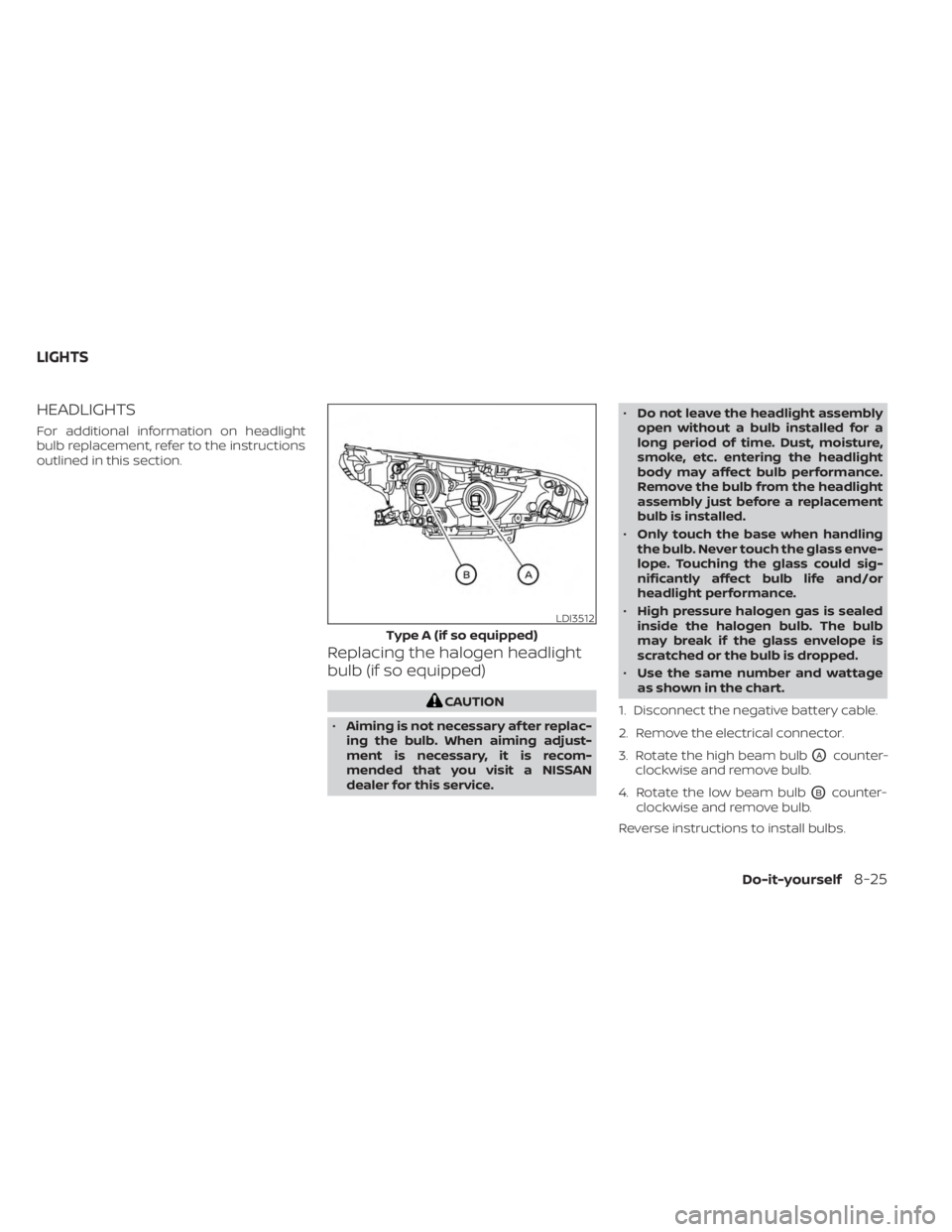
1. Disconnect the negative battery cable.
2. Remove the electrical connector.
3. Rotate the high beam bulb
OAcounter-
clockwise and remove bulb.
4. Rotate the low beam bulb
OBcounter-
clockwise and remove bulb.
Reverse instructions to install bulbs.
LDI3512
Type A (if so equipped)
LIGHTS
Do-it-yourself8-25
Page 521 of 556

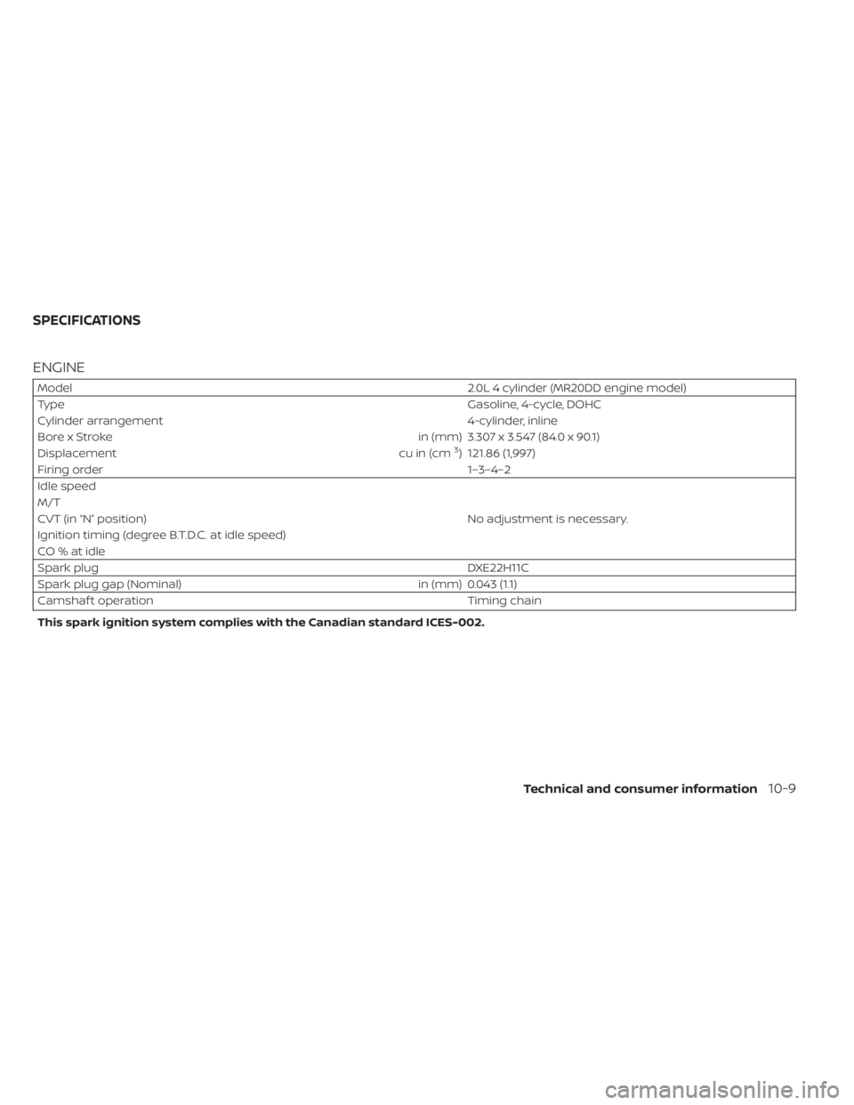
ENGINE
Model2.0L 4 cylinder (MR20DD engine model)
Type Gasoline, 4-cycle, DOHC
Cylinder arrangement 4-cylinder, inline
Bore x Stroke in (mm) 3.307 x 3.547 (84.0 x 90.1)
Displacement cu in (cm
3) 121.86 (1,997)
Firing order 1–3–4–2
Idle speed
No adjustment is necessary.
M/T
CVT (in “N” position)
Ignition timing (degree B.T.D.C. at idle speed)
CO%atidle
Spark plug DXE22H11C
Spark plug gap (Nominal) in (mm) 0.043 (1.1)
Camshaf t operation Timing chain
This spark ignition system complies with the Canadian standard ICES-002.
SPECIFICATIONS
Technical and consumer information10-9