2023 NISSAN SENTRA fuse
[x] Cancel search: fusePage 16 of 556

2.0L 4 cylinder (MR20DD engine model)
1. Engine oil filler cap (P. 8-6)
2. Brake and clutch (if so equipped) fluidreservoir (P. 8-10)
3. Fuse and relay box (P. 8-20)
4. Battery (P. 8-13)
5. Air cleaner (P. 8-17)
6. Engine oil dipstick (P. 8-6)
7. Drive belt location (P. 8-15)
8. Windshield-washer fluid reservoir
(P. 8-11)
9. Engine coolant reservoir (P. 8-5)
Refer to the page number indicated in
parentheses for operating details.
NOTE:
Your vehicle may not be equipped with
an engine cover.
LDI3477
ENGINE COMPARTMENT CHECK
LOCATIONS
0-8Illustrated table of contents
Page 115 of 556
Rear seat belt reminder
This warning appears for 35 seconds af ter
the ignition is placed in the ON position and
the engine is started.
This warning message shows the status of
the three rear seat belts. When one of the
rear seat belts are buckled, the corre-
sponding rear seat belt indicator will ap-
pear grey. When one of the rear seat belts
are unbuckled, the corresponding rear seat
belt indicator will appear red.
Af ter a change in buckle status, a chime will
sound and the warning will appear for an-
other 35 seconds.
Release Parking Brake
This warning appears when the parking
brake is set and the vehicle is driven.
Reminder: Turn OFF
Headlights
This warning appears when the headlights
are lef t in the ON position when exiting the
vehicle. Place the headlight switch in the
OFF or AUTO position. For additional infor-
mation, see “Headlight and turn signal
switch” (P. 2-52).
Shif t to Park
This warning appears when the ignition
switch is in the AUTO ACC or OFF position
and the shif t lever is not in the P (Park)
position. Also, a chime sounds when the
ignition switch is in the AUTO ACC or OFF
position.
If this warning appears, move the shif t lever
to the P (Park) position and start the engine.
Shipping Mode On Push Storage Fuse
This warning may appear if the extended
storage switch is not pushed in. When this
warning appears, push in the extended
storage switch to turn off the warning. For
additional information, see “Extended stor-
age switch” (P. 2-65), and/or “Fuses” (P. 8-20).
Tire Pressure Low - Add Air
This warning appears when the low tire
pressure warning light in the meter illumi-
nates and low tire pressure is detected. The
warning appears each time the ignition
switch is placed in the ON position as long
as the low tire pressure warning light re-
mains illuminated. If this warning appears,
stop the vehicle and adjust the tire pres-
sures of all four tires to the recommended
COLD tire pressure shown on the Tire andLoading Information label. For additional
information, see “Low tire pressure warning
light” (P. 2-13) and “Tire Pressure Monitoring
System (TPMS)” (P. 5-5).
TPMS Error: See Owner’s Manual
This warning appears when there is an er-
ror with your TPMS. If this warning comes
on, have the system checked. It is recom-
mended that you visit a NISSAN dealer for
this service.
Transmission Shif t Position
indicator
This indicator shows the transmission shif t
position.
CVT (AT) hot Power reduced
This transmission has a high fluid tem-
perature protection mode. If the fluid tem-
perature becomes too high (for example,
climbing steep grades in high tempera-
tures with heavy loads, such as when tow-
ing a trailer), engine power and, under
some conditions, vehicle speed will be de-
creased automatically to reduce the
chance of transmission damage. Vehicle
speed can be controlled with the accelera-
tor pedal, but the engine and vehicle speed
may be reduced.
Instruments and controls2-29
Page 130 of 556
OFF or AUTO position. For additional infor-
mation, see “Headlight and turn signal
switch” (P. 2-52).
Rotate Steering Wheel and
Push Start Switch
This indicator appears when the steering
lock cannot be released.
If this indicator appears, push the ignition
switch while lightly turning the steering
wheel right and lef t.
Shif t to Park
This warning appears when the ignition
switch is in the AUTO ACC or OFF position
and the shif t lever is not in the P (Park)
position. Also, a chime sounds when the
ignition switch is in the AUTO ACC or OFF
position.
If this warning appears, move the shif t lever
to the P (Park) position and start the engine.
Shipping Mode On Push Storage Fuse
This warning may appear if the extended
storage switch is not pushed in. When this
warning appears, push in the extended
storage switch to turn off the warning. For
additional information, see “Extended stor-
age switch” (P. 2-65), and/or “Fuses” (P. 8-20).
Timer Alert — Time for a
break?
This indicator appears when the set time is
reached. The time can be set up to six
hours. For additional information, see “Set-
tings” (P. 2-34).
Tire Pressure Low - Add Air
This warning appears when the low tire
pressure warning light in the meter illumi-
nates and low tire pressure is detected. The
warning appears each time the ignition
switch is placed in the ON position as long
as the low tire pressure warning light re-
mains illuminated. If this warning appears,
stop the vehicle and adjust the tire pres-
sures of all four tires to the recommended
COLD tire pressure shown on the Tire and
Loading Information label. For additional
information, see “Low tire pressure warning
light” (P. 2-13) and “Tire Pressure Monitoring
System (TPMS)” (P. 5-5).
Transmission Shif t Position
indicator
This indicator shows the transmission shif t
position.
CVT (AT) hot Power reduced
This transmission has a high fluid tem-
perature protection mode. If the fluid tem-
perature becomes too high (for example,
climbing steep grades in high tempera-
tures with heavy loads, such as when tow-
ing a trailer), engine power and, under
some conditions, vehicle speed will be de-
creased automatically to reduce the
chance of transmission damage. Vehicle
speed can be controlled with the accelera-
tor pedal, but the engine and vehicle speed
may be reduced.
WARNING
When the high fluid temperature pro-
tection mode operation occurs, vehicle
speed may be gradually reduced. The
reduced speed may be lower than
other traffic, which could increase the
chance of a collision. Be especially
careful when driving. If necessary, pull
to the side of the road at a safe place
and allow the transmission to return to
normal operation; or have it repaired if
necessary.
2-44Instruments and controls
Page 150 of 556
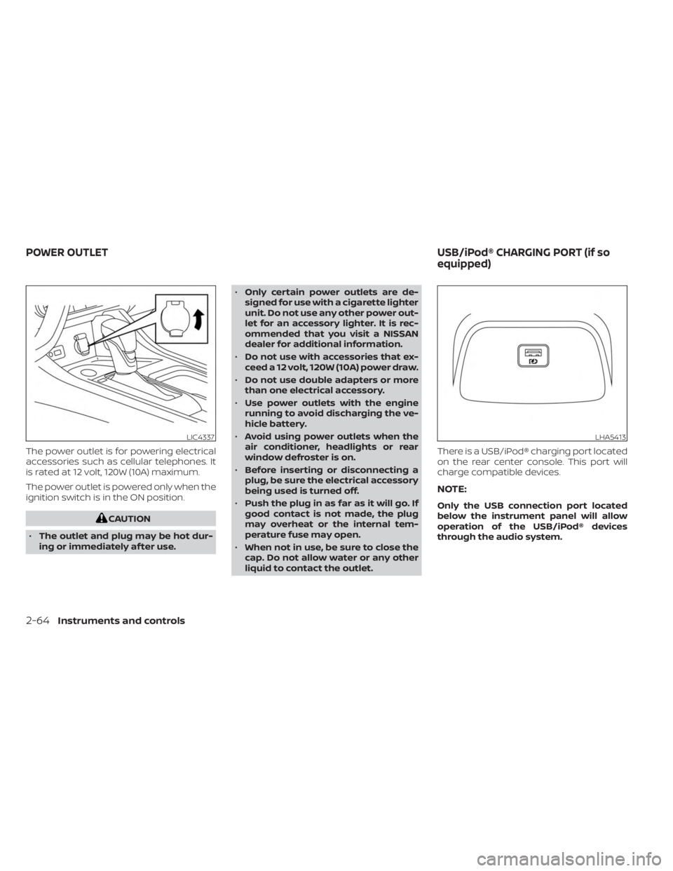
The power outlet is for powering electrical
accessories such as cellular telephones. It
is rated at 12 volt, 120W (10A) maximum.
The power outlet is powered only when the
ignition switch is in the ON position.
CAUTION
• The outlet and plug may be hot dur-
ing or immediately af ter use. •
Only certain power outlets are de-
signed for use with a cigarette lighter
unit. Do not use any other power out-
let for an accessory lighter. It is rec-
ommended that you visit a NISSAN
dealer for additional information.
• Do not use with accessories that ex-
ceed a 12 volt, 120W (10A) power draw.
• Do not use double adapters or more
than one electrical accessory.
• Use power outlets with the engine
running to avoid discharging the ve-
hicle battery.
• Avoid using power outlets when the
air conditioner, headlights or rear
window defroster is on.
• Before inserting or disconnecting a
plug, be sure the electrical accessory
being used is turned off.
• Push the plug in as far as it will go. If
good contact is not made, the plug
may overheat or the internal tem-
perature fuse may open.
• When not in use, be sure to close the
cap. Do not allow water or any other
liquid to contact the outlet. There is a USB/iPod® charging port located
on the rear center console. This port will
charge compatible devices.
NOTE:
Only the USB connection port located
below the instrument panel will allow
operation of the USB/iPod® devices
through the audio system.
LIC4337LHA5413
POWER OUTLET
USB/iPod® CHARGING PORT (if so
equipped)
2-64Instruments and controls
Page 151 of 556
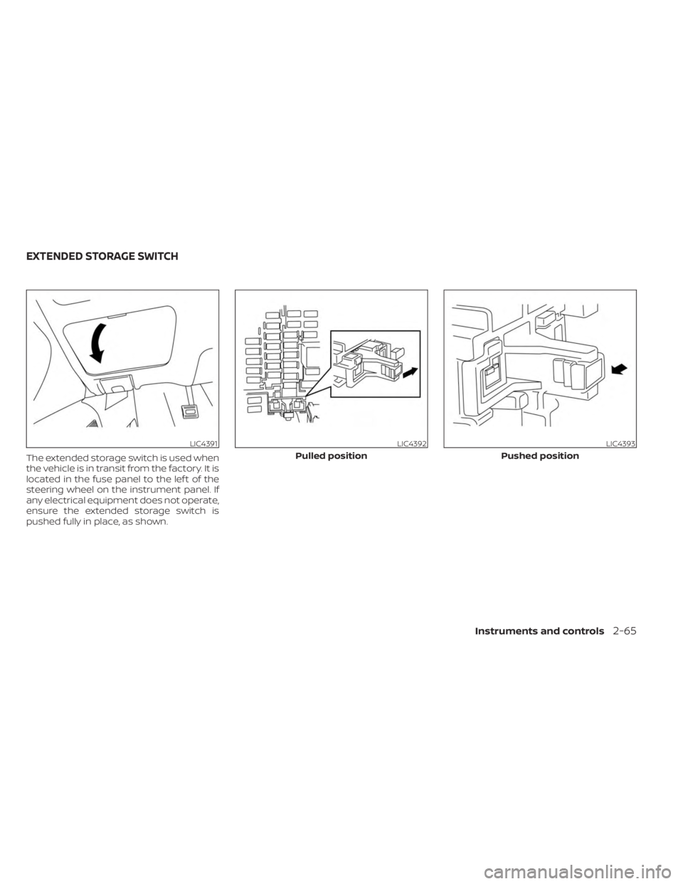
The extended storage switch is used when
the vehicle is in transit from the factory. It is
located in the fuse panel to the lef t of the
steering wheel on the instrument panel. If
any electrical equipment does not operate,
ensure the extended storage switch is
pushed fully in place, as shown.
LIC4391LIC4392
Pulled position
LIC4393
Pushed position
EXTENDED STORAGE SWITCH
Instruments and controls2-65
Page 447 of 556

8 Do-it-yourself
Maintenance precautions.......................8-2
Engine compartment check locations ...........8-3
Engine cooling system ..........................8-4
Checking engine coolant level ................8-5
Changing engine coolant ....................8-5
Engine oil .......................................8-6
Checking engine oil level .....................8-6
Changing engine oil and oil filter ..............8-6
Continuously Variable Transmission (CVT)
fluid (if so equipped) ............................ 8-10
Brake and clutch (if so equipped) fluid ..........8-10
Brake fluid ................................... 8-10
Clutch (if so equipped) fluid ...................8-11
Windshield-washer fluid .........................8-11
Windshield-washer fluid reservoir ............8-11
Battery......................................... 8-13
Jump starting ............................... 8-14
Variable voltage control system ................8-15
Drive belt ....................................... 8-15
Spark plugs .................................... 8-16
Replacing spark plugs .......................8-16
Air cleaner ..................................... 8-17In-cabin microfilter
.......................... 8-17
Windshield wiper blades ........................8-18
Cleaning .................................... 8-18
Replacing ................................... 8-18
Brakes ......................................... 8-19
Fuses .......................................... 8-20
Engine compartment .......................8-20
Passenger compartment ...................8-22
Battery replacement ........................... 8-23
NISSAN Intelligent Key® ......................8-23
Lights .......................................... 8-25
Headlights .................................. 8-25
Turn signal bulb ............................. 8-26
Fog lights (if so equipped) ...................8-26
Exterior and interior lights ...................8-27
Wheels and tires ...............................
8-29
Tir
e pressure ................................ 8-29
Tire labeling ................................. 8-33
Types of tires ................................ 8-36
Tire chains .................................. 8-37
Changing wheels and tires ..................8-38
Page 449 of 556

2.0L 4 cylinder (MR20DD engine model)
1. Engine oil filler cap
2. Brake and clutch (if so equipped) fluidreservoir
3. Fuse and relay box
4. Battery
5. Air cleaner
6. Engine oil dipstick
7. Drive belt location
8. Windshield-washer fluid reservoir
9. Engine coolant reservoir
NOTE:
Your vehicle may not be equipped with
an engine cover.
LDI3477
ENGINE COMPARTMENT CHECK
LOCATIONS
Do-it-yourself8-3
Page 466 of 556
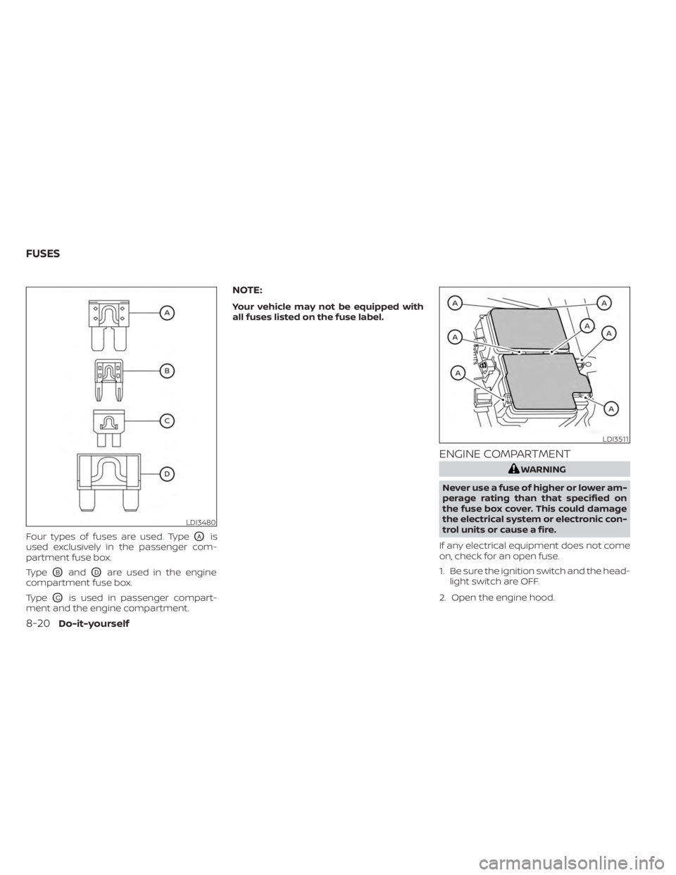
Four types of fuses are used. TypeOAis
used exclusively in the passenger com-
partment fuse box.
Type
OBandODare used in the engine
compartment fuse box.
Type
OCis used in passenger compart-
ment and the engine compartment.
NOTE:
Your vehicle may not be equipped with
all fuses listed on the fuse label.
ENGINE COMPARTMENT
WARNING
Never use a fuse of higher or lower am-
perage rating than that specified on
the fuse box cover. This could damage
the electrical system or electronic con-
trol units or cause a fire.
If any electrical equipment does not come
on, check for an open fuse.
1. Be sure the ignition switch and the head- light switch are OFF.
2. Open the engine hood.
LDI3480
LDI3511
FUSES
8-20Do-it-yourself