2023 NISSAN QASHQAI audio
[x] Cancel search: audioPage 236 of 508

4-30Monitor, heater, air conditioner, audio and phone systems
more than 36°F (2°C). This dehumidifies
the air which helps defog the windshield.
The air recirculation mode automatically
turns off, allowing outside air to be drawn
into the passenger compartment to
further improve the defogging perfor-
mance.
The air conditioner is always on in front
defroster or
mode, regardless of
whether the indicator light is on or off.
NOTE:
. The air conditioner system should
be operated for approximately 10
minutes at least once a month. This
helps prevent damage to the air
conditioner system due to the lack
of lubrication.
. A visible mist may be seen coming
from the ventilators in hot, humid
conditions as the air is cooled ra-
pidly. This does not indicate a mal-
function.
. If the engine coolant temperature
becomes too high, the air recircula-
tion mode will be activated and the
indicator light will come on automa-
tically.
. If the engine coolant temperature
gauge indicates engine coolant tem-
perature over the normal range, turn
the air conditioner off. (See “If your
vehicle overheats” (P.6-16).)
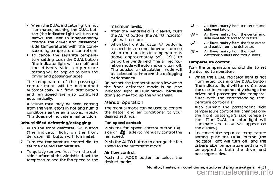
JVH0665X
1. Front defrosterbutton
2. ON·OFF button/Temperature control dial (driver side)
3. MODE button
4. Display screen
5. A/C (Air Conditioner) button
6. DUAL button/Temperature control dial (passenger side)
7. Rear defroster
button (See “Rear
window and outside mirror defroster
switch” (P.2-51).)
8. Air recirculation
button
9. Fan speed controlbutton
10. AUTO button
11. Outside air circulation
button
AUTOMATIC AIR CONDITIONER AND
HEATER
Automatic operation (AUTO)
The AUTO mode may be used year-round
as the system automatically controls the
air conditioner to a constant tempera-
ture, air flow distribution and fan speed
after the desired temperature is set
manually.
Cooling and dehumidified heating:
1. Push the AUTO button (the indicator light will turn on).
2. Turn the temperature control dial to set the desired temperature.
Page 237 of 508

.When the DUAL indicator light is notilluminated, pushing the DUAL but-
ton (the indicator light will turn on)
allows the user to independently
change the driver and passenger
side temperatures with the corre-
sponding temperature control dial.
.To cancel the separate tempera-ture setting, push the DUAL button
(the indicator light will turn off) and
the driver’s side temperature
setting will be applied to both the
driver and passenger sides.
The temperature of the passenger
compartment will be maintained
automatically. Air flow distribution
and fan speed are also controlled
automatically.
A visible mist may be seen coming
from the ventilators in hot and humid
conditions as the air is cooled rapidly.
This does not indicate a malfunction.
Dehumidified defrosting/defogging:
1. Push the front defroster
button
(The indicator light on the front
defroster
button will illuminate).
2. Turn the temperature control dial to set the desired temperature.
. To quickly remove frost from the out-
side surface of the windshield, set the
temperature and the fan speed to the maximum levels.
. After the windshield is cleared, push
the AUTO button (the AUTO indicator
light will turn on).
. When the front defroster
button is
pushed, the air conditioner will turn on
when the outside air temperature is
above approximately 36°F (2°C) to
defog the windshield. The air recircu-
lation mode will automatically turn off.
The outside air circulation mode will
be selected to improve the defogging
performance.
Do not set the temperature too low when
the front defroster mode is on (the
indicator light is illuminated), because
doing so may fog up the windshield.
Manual operation
The manual mode can be used to control
the heater and air conditioner to your
desired settings.
Fan speed control:
Push the fan speed control button (
side orside) to manually control the
fan speed.
Push the AUTO button to change the fan
speed to the automatic mode.
Air flow control:
Push the MODE button to select the
desired mode:
— Air flows mainly from the center and
side ventilators.
— Air flows mainly from the center andside ventilators and foot outlets.
— Air flows mainly from the foot outletand partly from the defroster.
— Air flows mainly from the frontdefroster outlets and foot outlets.
Temperature control:
Turn the temperature control dial to set
the desired temperature.
.When the DUAL indicator light is not
illuminated, pushing the DUAL button
(the indicator light will turn on) allows
the user to independently change the
driver and passenger side tempera-
tures with the corresponding tem-
perature control dial.
Also turning the passenger’s side
temperature control dial changes only
the front passenger’s side tempera-
ture. (The DUAL indicator light will
illuminate and DUAL will appear on
the display.)
. To cancel the separate temperature
setting, push the DUAL button (the
indicator light will turn off) and the
driver’s side temperature setting will
be applied to both the driver and
passenger sides.
Monitor, heater, air conditioner, audio and phone systems4-31
Page 238 of 508

4-32Monitor, heater, air conditioner, audio and phone systems
Air intake control:
.Push the air recirculation
button
to recirculate interior air inside the
vehicle. The indicator light on the
button will come on.
The air recirculation cannot be acti-
vated when the air conditioner is in
the front defrosting mode.
. Push the outside air circulation
button to draw outside air into the
passenger compartment. The indica-
tor light on the button will come on.
. To control the air intake automatically,
push and hold either the air recircula-
tion
button or the outside air
circulationbutton (whichever but-
ton with the indicator light illumi-
nated). The indicator lights (both air
recirculation
and outside air cir-
culationbuttons) will flash twice,
and then the air intake will switch to
automatic control. When the auto-
matic control is set, the system auto-
matically alternates between the
outside air circulation and the air
recirculation modes. (The indicator
light of the active mode will turn on.)
NOTE:
Even if the system is manually set to the
air recirculation mode, when both out-
side temperature and coolant tempera-
ture are low, the system may automatically switch to the outside air
circulation mode.
To turn the system off:
To turn off the heater and air conditioner,
push the ON·OFF button.
Push the ON·OFF button again, the sys-
tem will turn on in the mode which was
used immediately before the system was
turned off.
Remote engine start logic (if so
equipped)
When the remote engine start function is
activated, the vehicles equipped with the
automatic air conditioner and heater may
go into automatic heating or cooling
mode depending on the outside and
cabin temperatures. During this period,
the display and the buttons will be
inoperable until the ignition switch is
placed in the ON position. When the
temperature is low, the rear defroster
and the heated steering wheel (if so
equipped) may also be activated auto-
matically with the activation of the re-
mote engine start function. (See “Remote
engine start” (P.3-23).)
JVH0727X
JVH0728X
Page 239 of 508

OPERATING TIPS (for automatic air
conditioner)
When the engine coolant temperature
and outside air temperature are low, the
air flow from the foot outlets may not
operate for a maximum of 150 seconds.
However, this is not a malfunction. After
the coolant temperature warms up, air
flow from the foot outlets will operate
normally.
The sensors
and, located on the
instrument panel, help maintain a con-
stant temperature. Do not put anything
on or around the sensors.
SERVICING AIR CONDITIONER
WARNING
The air conditioner system contains
refrigerant under high pressure. To
avoid personal injury, any air condi-
tioner service should be done only by
an experienced technician with the
proper equipment.
The air conditioner system in your vehicle
is charged with a refrigerant designed
with the environment in mind.
This refrigerant will not harm the
earth’s ozone layer. However, it maycontribute in a small part to global
warming.
Special charging equipment and lubricant
are required when servicing your vehicle’s
air conditioner. Using improper refriger-
ants or lubricants will cause severe da-
mage to the air conditioner system. (See
“Air conditioning system refrigerant and
oil recommendations” (P.10-6).)
A NISSAN dealer will be able to service
your environmentally friendly air condi-
tioner system.
In-cabin microfilter
The air conditioner system is equipped
with an in-cabin microfilter. To make sure
the air conditioner heats, defogs, and
ventilates efficiently, replace the filter
according to the specified maintenance
intervals listed in the "9. Maintenance and
schedules" section. It is recommended to
visit a NISSAN dealer to replace the filter.
The filter should be replaced if the air flow
decreases significantly or if windows fog
up easily when operating the heater or air
conditioner.SAA2374
To remove the antenna, hold the bottom
of the antenna and turn it counterclock-
wise.
To install the antenna, turn the antenna
clockwise and tighten.
CAUTION
.
To avoid damaging or deforming
the antenna, be sure to remove
the antenna under the following
conditions.
— The vehicle enters a garage
with a low ceiling.
Monitor, heater, air conditioner, audio and phone systems4-33
ANTENNA
Page 240 of 508

4-34Monitor, heater, air conditioner, audio and phone systems
— The vehicle is covered with acar cover.
. Be sure that antenna is removed
before the vehicle enters an auto-
matic car wash.
. Always properly tighten the an-
tenna rod during installation.
Otherwise, the antenna rod may
break during vehicle operation.
. A build up of ice on the antenna
can affect radio performance. Re-
move the ice to restore radio
reception.
. When removing snow from the
roof, do not apply strong force to
the antenna. That may cause
broken antenna and roof panel
dent.
. When using a high pressure car
wash, keep the high pressure
nozzle away from the antenna.
The seal may be deformed or
damaged.
. The radio performance may be
affected if cargo carried on the
roof blocks the radio signal. If
possible, do not put cargo near
the antenna.When installing a car phone or a CB radio
in your vehicle, be sure to observe the
following precautions, otherwise the new
equipment may adversely affect the elec-
tronic control modules and electronic
control system harness.
WARNING
.A cellular phone should not be
used for any purpose while driv-
ing so full attention may be given
to vehicle operation. Some juris-
dictions prohibit the use of cellu-
lar phones while driving.
. If you must make a call while your
vehicle is in motion, the hands-
free cellular phone operational
mode (if so equipped) is highly
recommended. Exercise extreme
caution at all times so full atten-
tion may be given to vehicle
operation.
. If a conversation in a moving
vehicle requires you to take
notes, pull off the road to a safe
location and stop your vehicle
before doing so.
CAUTION
.Keep the antenna as far away as
possible from the electronic con-
trol modules.
. Keep the antenna wire more than
8 in (20 cm) away from the
electronic control system har-
ness. Do not route the antenna
wire next to any harness.
. Adjust the antenna standing-
wave ratio as recommended by
the manufacturer.
. Connect the ground wire from the
CB radio chassis to the body.
. For details, it is recommended
you visit a NISSAN dealer.
CAR PHONE OR CB RADIO
Page 256 of 508

5-16Starting and driving
Continuously Variable Transmis-
sion (CVT) models
The ignition lock is designed so that the
ignition switch position cannot be
switched to OFF until the shift lever is
moved to the P (Park) position.
When the ignition switch cannot be
pushed toward the OFF position, proceed
as follows:
1. Move the shift lever into the P (Park)position.
2. Push the ignition switch. The ignition switch position will change to the ON
position.
3. Push the ignition switch again to the OFF position.
The shift lever can be moved from the P
(Park) position if the ignition switch is in
the ON position and the brake pedal is
depressed.
PUSH-BUTTON IGNITION SWITCH
POSITIONS
LOCK (Normal parking position)
The ignition switch can only be locked at
this position.
The ignition switch will lock when any
door is opened or closed with the ignition
switched off.
ON (Normal operating position)
The ignition system and the electrical
accessory power activate at this position
without the engine turned on.
The ON position has a battery saver
feature that will place the ignition switch
in the OFF position, if the vehicle is not
running, after some time under the fol-
lowing conditions:
. all doors are closed.
. shift lever is in P (Park) position (CVT
model) or N (Neutral) position (MT
model).
The battery saver feature will be can-
celled if any of the following occur:
. any door is opened.
. shift lever is moved out of the P (Park)
position (CVT model). .
ignition switch changes position.
OFF position
The engine is turned off in this position.
Auto ACC position
With the vehicle in the P (Park) position
(CVT models) or the N (Neutral) position
(MT models), the Intelligent Key with you
and the ignition placed from ON to OFF,
the radio can still be used for a period of
time, or until the driver’s door is opened.
After a period of time, functions such as
radio, navigation (if so equipped), and
Bluetooth® Hands-Free Phone System
may be restarted by turning on the audio
system (see the separate NissanConnect®
Owner’s Manual), or by pushing the UN-
LOCK button on the Intelligent Key for up
to a total of 30 minutes.
EMERGENCY ENGINE SHUT OFF
To shut off the engine in an emergency
situation while driving, perform the fol-
lowing procedure:
.Rapidly push the push-button ignition
switch 3 consecutive times in less
than 1.5 seconds, or
. Push and hold the push-button igni-
tion switch for more than 2 seconds.
Page 289 of 508

when certain objects are present
such as:
— Pedestrians, bicycles, animals.
— Vehicles such as motorcycles,low height vehicles, or high
ground clearance vehicles.
— Oncoming vehicles.
— Vehicles remaining in the de- tection zone when you accel-
erate from a stop.
— A vehicle merging into an adjacent lane at a speed ap-
proximately the same as your
vehicle.
— A vehicle approaching rapidly from behind.
— A vehicle which your vehicle overtakes rapidly.
— A vehicle that passes through the detection zone quickly.
— When overtaking several vehi- cles in a row, the vehicles after
the first vehicle may not be
detected if they are traveling
close together.
. The radar sensor’s detection zone
is designed based on a standard
lane width. When driving in a wider lane, the radar sensors
may not detect vehicles in an
adjacent lane. When driving in a
narrow lane, the radar sensors
may detect vehicles driving two
lanes away.
. The radar sensors are designed
to ignore most stationary objects,
however objects such as guard-
rails, walls, foliage and parked
vehicles may occasionally be de-
tected. This is a normal operation
condition.
. The following conditions may re-
duce the ability of the radar to
detect other vehicles:
— Severe weather
— Road spray
— Ice/frost/dirt build-up on the
vehicle
. Do not attach stickers (including
transparent material), install ac-
cessories or apply additional
paint near the radar sensors.
These conditions may reduce the
ability of the radar to detect other
vehicles.
. Excessive noise (for example,
audio system volume, open vehi-
cle window) will interfere with the chime sound, and it may not be
heard.
BSW DRIVING SITUATIONS
Indicator on
Indicator off
Indicator flashing
Starting and driving5-49
Page 299 of 508

— Illustration: When a vehicle
parked next to you obstructs
the beam of the radar sensor.
— Illustration
: When the vehi-
cle is parked in an angled
parking space.
— Illustration
: When the vehi-
cle is parked on inclined
ground.
— Illustration
: When an ap-
proaching vehicle turns into
your vehicle’s parking lot aisle.
— Illustration
: When the angle
formed by your vehicle and
approaching vehicle is small
. The following conditions may re-
duce the ability of the radar to
detect other vehicles:
— Severe weather
— Road spray
— Ice/frost/dirt build-up on the
vehicle
. Do not attach stickers (including
transparent material), install ac-
cessories or apply additional
paint near the radar sensors.
These conditions may reduce the
ability of the radar to detect other
vehicles .
Excessive noise (e.g. audio sys-
tem volume, open vehicle win-
dow) will interfere with the
chime sound, and it may not be
heard.JVS0172X
Illustration 1
JVS0173XIllustration 2
Starting and driving5-59