2023 NISSAN QASHQAI service indicator
[x] Cancel search: service indicatorPage 130 of 508
2-48Instruments and controls
SIC2045
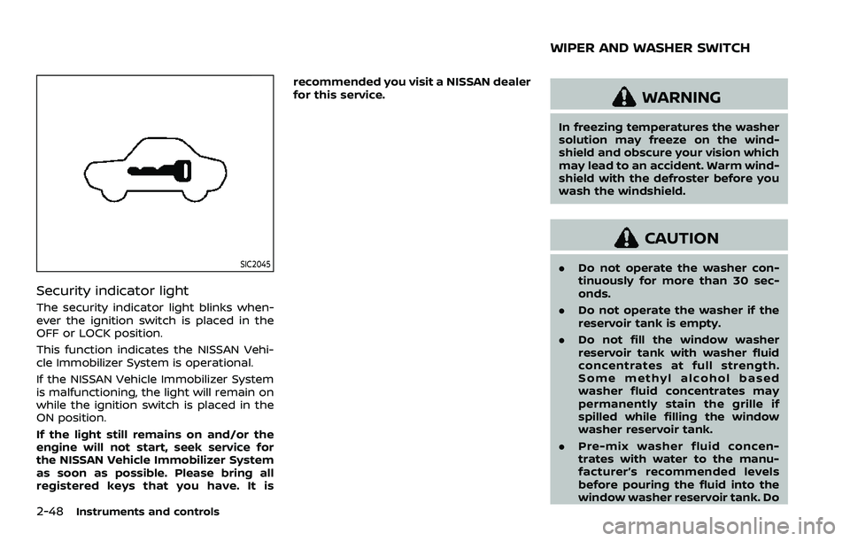
Security indicator light
The security indicator light blinks when-
ever the ignition switch is placed in the
OFF or LOCK position.
This function indicates the NISSAN Vehi-
cle Immobilizer System is operational.
If the NISSAN Vehicle Immobilizer System
is malfunctioning, the light will remain on
while the ignition switch is placed in the
ON position.
If the light still remains on and/or the
engine will not start, seek service for
the NISSAN Vehicle Immobilizer System
as soon as possible. Please bring all
registered keys that you have. It isrecommended you visit a NISSAN dealer
for this service.
WARNING
In freezing temperatures the washer
solution may freeze on the wind-
shield and obscure your vision which
may lead to an accident. Warm wind-
shield with the defroster before you
wash the windshield.
CAUTION
.
Do not operate the washer con-
tinuously for more than 30 sec-
onds.
. Do not operate the washer if the
reservoir tank is empty.
. Do not fill the window washer
reservoir tank with washer fluid
concentrates at full strength.
Some methyl alcohol based
washer fluid concentrates may
permanently stain the grille if
spilled while filling the window
washer reservoir tank.
. Pre-mix washer fluid concen-
trates with water to the manu-
facturer’s recommended levels
before pouring the fluid into the
window washer reservoir tank. Do
WIPER AND WASHER SWITCH
Page 142 of 508
2-60Instruments and controls
indicator light will turn off.
NOTE:
If the surface temperature of the steer-
ing wheel is above 68°F (20°C) when the
switch is turned on, the system will not
heat the steering wheel. This is not a
malfunction.
WARNING
Do not use or allow occupants to use
the seat heater if you or the occu-
pants cannot monitor elevated seat
temperatures or have an inability to
feel pain in body parts that contact
the seat. Use of the seat heater by
such people could result in serious
injury.
CAUTION
.The battery could run down if the
seat heater is operated while the
engine is not running.
. Do not use the seat heater for
extended periods or when no one
is using the seat.
. Do not put anything on the seat
which insulates heat, such as a
blanket, cushion, seat cover, etc.
Otherwise, the seat may become
overheated.
. Do not place anything hard or
heavy on the seat or pierce it with
a pin or similar object. This may
result in damage to the heater. .
Any liquid spilled on the heated
seat should be removed immedi-
ately with a dry cloth.
. When cleaning the seat, never use
gasoline, thinner, or any similar
materials.
. If any malfunctions are found or
the heated seat does not operate,
turn the switch off and have the
system checked. It is recom-
mended you visit a NISSAN dealer
for this service.
HEATED SEATS (if so equipped)
Page 150 of 508
2-68Instruments and controls
from the TCU antenna may ad-
versely affect the operation of the
pacemaker while using the Nis-
sanConnect® Services.
WAC0510X
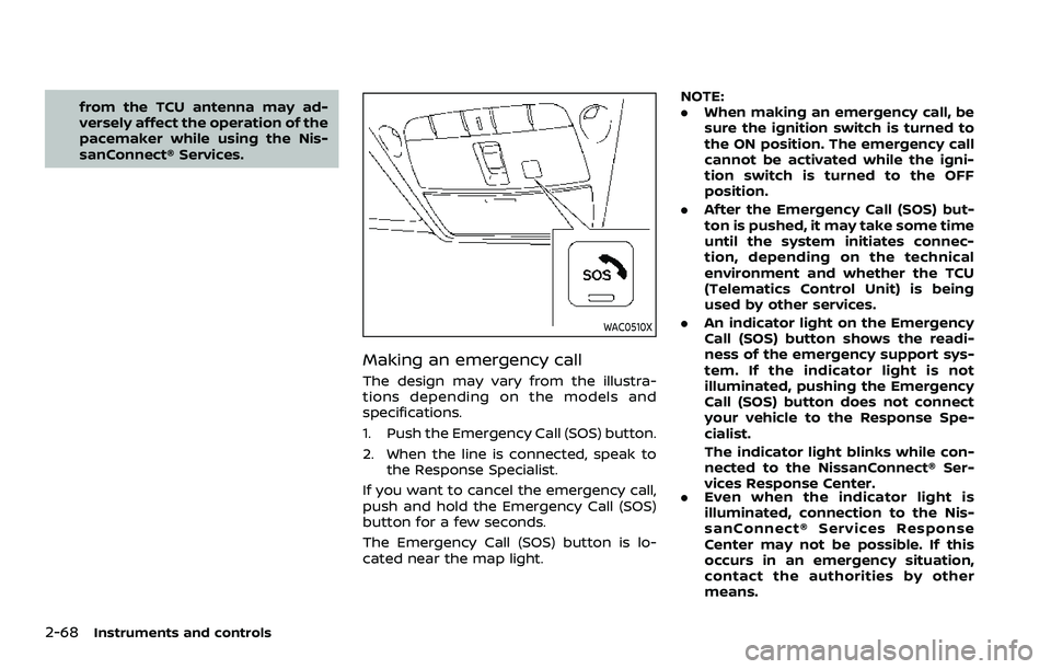
Making an emergency call
The design may vary from the illustra-
tions depending on the models and
specifications.
1. Push the Emergency Call (SOS) button.
2. When the line is connected, speak tothe Response Specialist.
If you want to cancel the emergency call,
push and hold the Emergency Call (SOS)
button for a few seconds.
The Emergency Call (SOS) button is lo-
cated near the map light. NOTE:
.
When making an emergency call, be
sure the ignition switch is turned to
the ON position. The emergency call
cannot be activated while the igni-
tion switch is turned to the OFF
position.
. After the Emergency Call (SOS) but-
ton is pushed, it may take some time
until the system initiates connec-
tion, depending on the technical
environment and whether the TCU
(Telematics Control Unit) is being
used by other services.
. An indicator light on the Emergency
Call (SOS) button shows the readi-
ness of the emergency support sys-
tem. If the indicator light is not
illuminated, pushing the Emergency
Call (SOS) button does not connect
your vehicle to the Response Spe-
cialist.
The indicator light blinks while con-
nected to the NissanConnect® Ser-
vices Response Center.
. Even when the indicator light is
illuminated, connection to the Nis-
sanConnect® Services Response
Center may not be possible. If this
occurs in an emergency situation,
contact the authorities by other
means.
Page 199 of 508
WARNING
.Gasoline is extremely flammable
and highly explosive under cer-
tain conditions. You could be
burned or seriously injured if it is
misused or mishandled. Always
stop engine and do not smoke or
allow open flames or sparks near
the vehicle when refueling.
. Do not attempt to top off the fuel
tank after the fuel pump nozzle
shuts off automatically. Contin-
ued refueling may cause fuel
overflow, resulting in fuel spray
and possibly a fire.
. Use only an original equipment
type fuel-filler cap as a replace-
ment. It has a built-in safety valve
needed for proper operation of
the fuel system and emission
control system. An incorrect cap
can result in a serious malfunc-
tion and possible injury. It could
also cause the malfunction indi-
cator light to come on.
. Never pour fuel into the throttle
body to attempt to start your
vehicle. .
Do not fill a portable fuel contain-
er in the vehicle or trailer. Static
electricity can cause an explosion
of flammable liquid, vapor or gas
in any vehicle or trailer. To reduce
the risk of serious injury or death
when filling portable fuel contain-
ers:
— Always place the container on
the ground when filling.
— Do not use electronic devices when filling.
— Keep the pump nozzle in con- tact with the container while
you are filling it.
— Use only approved portable fuel containers for flammable
liquid.
CAUTION
. If fuel is spilled on the vehicle
body, flush it away with water to
avoid paint damage.
. Insert the cap straight into the
fuel-filler tube, then tighten until
the fuel-filler cap clicks. Failure to
tighten the fuel-filler cap properly
may cause the
malfunction indicator light (MIL) to illuminate.
If the
light illuminates be-
cause the fuel-filler cap is loose
or missing, tighten or install the
cap and continue to drive the
vehicle. The
light should turn
off after a few driving trips. If the
light does not turn off after a
few driving trips, have the vehicle
inspected. It is recommended you
visit a NISSAN dealer for this
service.
For additional information, see
“Malfunction Indicator Light
(MIL)” (P.2-16).
. The LOOSE FUEL CAP warning
message will be displayed if the
fuel-filler cap is not properly tigh-
tened. It may take a few driving
trips for the message to be dis-
played. Failure to tighten the fuel-
filler cap properly after the LOOSE
FUEL CAP warning message is
displayed may cause the
Malfunction Indicator Light (MIL)
to illuminate.
Pre-driving checks and adjustments3-29
Page 245 of 508

away from the exhaust system
components.
. Do not stop or park the vehicle
over flammable materials such as
dry grass, wastepaper or rags.
They may ignite and cause a fire.
CAUTION
.Do not use leaded gasoline. De-
posits from leaded gasoline will
seriously reduce the three-way
catalyst’s ability to help reduce
exhaust pollutants.
. Keep your engine tuned up. Mal-
functions in the ignition, fuel in-
jection, or electrical systems can
cause overrich fuel flow into the
three-way catalyst, causing it to
overheat. Do not keep driving if
the engine misfires, or if notice-
able loss of performance or other
unusual operating conditions are
detected. Have the vehicle in-
spected. It is recommended you
visit a NISSAN dealer for this
service.
. Avoid driving with an extremely
low fuel level. Running out of fuel
could cause the engine to misfire, damaging the three-way catalyst.
. Do not race the engine while
warming it up.
. Do not push or tow your vehicle
to start the engine.
TIRE PRESSURE MONITORING SYS-
TEM (TPMS)
Each tire, including the spare (if provided),
should be checked monthly when cold
and inflated to the inflation pressure
recommended by the vehicle manufac-
turer on the vehicle placard or tire infla-
tion pressure label. (If your vehicle has
tires of a different size than the size
indicated on the vehicle placard or tire
inflation pressure label, you should deter-
mine the proper tire inflation pressure for
those tires.)
As an added safety feature, your vehicle
has been equipped with a Tire Pressure
Monitoring System (TPMS) that illumi-
nates a low tire pressure telltale when
one or more of your tires is significantly
under-inflated. Accordingly, when the low
tire pressure telltale illuminates, you
should stop and check your tires as soon
as possible, and inflate them to the
proper pressure. Driving on a significantly
under-inflated tire causes the tire to
overheat and can lead to tire failure. Under-inflation also reduces fuel effi-
ciency and tire tread life, and may affect
the vehicle’s handling and stopping abil-
ity.
Please note that the TPMS is not a
substitute for proper tire maintenance,
and it is the driver’s responsibility to
maintain correct tire pressure, even if
under-inflation has not reached the level
to trigger illumination of the TPMS low
tire pressure telltale.
Your vehicle has also been equipped with
a TPMS malfunction indicator to indicate
when the system is not operating prop-
erly. The TPMS malfunction indicator is
combined with the low tire pressure tell-
tale. When the system detects a malfunc-
tion, the telltale will flash for
approximately one minute and then re-
main continuously illuminated. This se-
quence will continue upon subsequent
vehicle start-ups as long as the malfunc-
tion exists. When the malfunction indica-
tor is illuminated, the system may not be
able to detect or signal low tire pressure
as intended. TPMS malfunctions may
occur for a variety of reasons, including
the installation of replacement or alter-
nate tires or wheels on the vehicle that
prevent the TPMS from functioning prop-
erly. Always check the TPMS malfunction
telltale after replacing one or more tires
Starting and driving5-5
Page 263 of 508
M1 (1st):
Use this position when climbing steep
hills slowly or driving slowly through deep
snow, sand or mud, or for maximum
engine braking on steep downhill grades.
.Remember not to drive at high speeds
for extended periods of time in lower
than M7 range. This reduces fuel
economy.
. In the manual shift mode, the trans-
mission may not shift to the se-
lected range. This helps maintain
driving performance and reduces
the chance of vehicle damage or
loss of control.
. In the manual shift mode, the trans-
mission automatically shifts down
to 1st gear before the vehicle comes
to a stop. When accelerating again, it
is necessary to shift up to the
desired range.
. When the CVT fluid temperature is
extremely low, the manual shift mode
may not work and automatically shift
as a drive mode. This is not a mal-
function. In this case, return the shift
lever to the D (Drive) position and drive
for a while and then shift to the
manual shift mode.
. When the CVT fluid temperature is
high, the shift range may upshift at a
lower engine speed than usual. This is not a malfunction.Accelerator downshift — In D posi-
tion —
For passing or hill climbing, fully depress
the accelerator pedal to the floor. This
shifts the transmission down into a lower
gear, depending on the vehicle speed.
High fluid temperature protection
mode
This transmission has a high fluid tem-
perature protection mode. If the fluid
temperature becomes too high (for ex-
ample, when climbing steep grades in
high temperature with heavy loads), en-
gine power and, under some conditions,
vehicle speed will be decreased automa-
tically to reduce the chance of transmis-
sion damage. Vehicle speed can be
controlled with the accelerator pedal,
but the engine and vehicle speed may
be limited.
Fail-safe
If the vehicle is driven under extreme
conditions, such as excessive wheel
spinning and subsequent hard braking,
the fail-safe system may be activated.
The MIL may illuminate to indicate the
fail-safe mode is activated. (See “Mal-
function Indicator Light (MIL)” (P.2-16).)
This will occur even if all electricalcircuits are functioning properly. In this
case, place the ignition switch in the
OFF position and wait for 10 seconds.
Then turn the switch back to the ON
position. The vehicle should return to its
normal operating condition. If it does
not return to its normal operating con-
dition, have the transmission checked
and repaired, if necessary. It is recom-
mended you visit a NISSAN dealer for
this service.
WARNING
When the high fluid temperature
protection mode or fail-safe opera-
tion occurs, vehicle speed may be
gradually reduced. The reduced
speed may be lower than other
traffic, which could increase the
chance of a collision. Be especially
careful when driving. If necessary,
pull to the side of the road at a safe
place and allow the transmission to
return to normal operation, or have it
repaired if necessary.
Starting and driving5-23
Page 270 of 508
5-30Starting and driving
.Be sure to deactivate the auto-
matic brake hold function when
using a car wash or towing your
vehicle.
. Make sure to place the shift lever
in the P (Park) position and apply
the parking brake when parking
your vehicle, riding on or off the
vehicle, or loading luggage. Fail-
ure to do so could cause the
vehicle to move or roll away
unexpectedly and result in ser-
ious personal injury or property
damage.
. If any of the following conditions
occur, the automatic brake hold
function may not function. Have
the system checked promptly. It
is recommended that you visit a
NISSAN dealer for this service.
Failure to operate the vehicle in
accordance with these conditions
could cause the vehicle to move
or roll away unexpectedly and
result in serious personal injury
or property damage.
— A warning message appears
in the vehicle information dis-
play.
— The indicator light on the automatic brake hold switch does not illuminate when the
switch is pushed.
. The automatic brake hold func-
tion will not be activated if the
Vehicle Dynamic Control (VDC)
OFF indicator light, electronic
parking brake warning light or
master warning light illuminate
and the Chassis Control System
Error message appears in the
vehicle information display.
. To maintain the braking force to
keep the vehicle to a standstill, a
noise may be heard. This is not a
malfunction.
JVP0497X
HOW TO ACTIVATE/DEACTIVATE
THE AUTOMATIC BRAKE HOLD
FUNCTION
How to activate the automatic
brake hold function
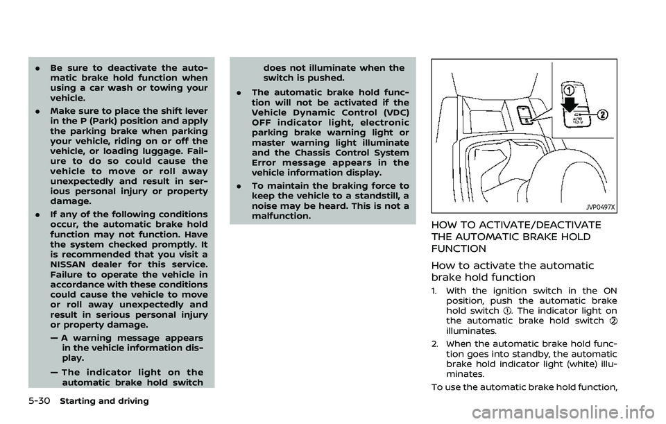
1. With the ignition switch in the ON
position, push the automatic brake
hold switch
. The indicator light on
the automatic brake hold switch
illuminates.
2. When the automatic brake hold func- tion goes into standby, the automatic
brake hold indicator light (white) illu-
minates.
To use the automatic brake hold function,
Page 279 of 508
the LDW system will resume operating
automatically and the LDW indicator will
stop flashing.
Condition B:
The warning function of the LDW system
is not designed to work under the follow-
ing conditions:
.When you operate the lane change
signal and change traveling lanes in
the direction of the signal. (The LDW
system will become operable again
approximately 2 seconds after the
lane change signal is turned off.)
. When the vehicle speed lowers to less
than approximately 37 MPH (60 km/h).
Action to take:
After the above conditions have finished
and the necessary operating conditions
are satisfied, the LDW system will resume.SYSTEM MALFUNCTION
If the LDW system malfunctions, it will
cancel automatically and “Malfunction”
will appear in the vehicle information
display. If the warning message appears
in the vehicle information display, pull off
the road to a safe location and stop the
vehicle. Place the ignition switch in the
OFF position and restart the engine. If the
warning message continues to appear in
the vehicle information display, have the
system checked. It is recommended that
you visit a NISSAN dealer for this service.
WAC0198X
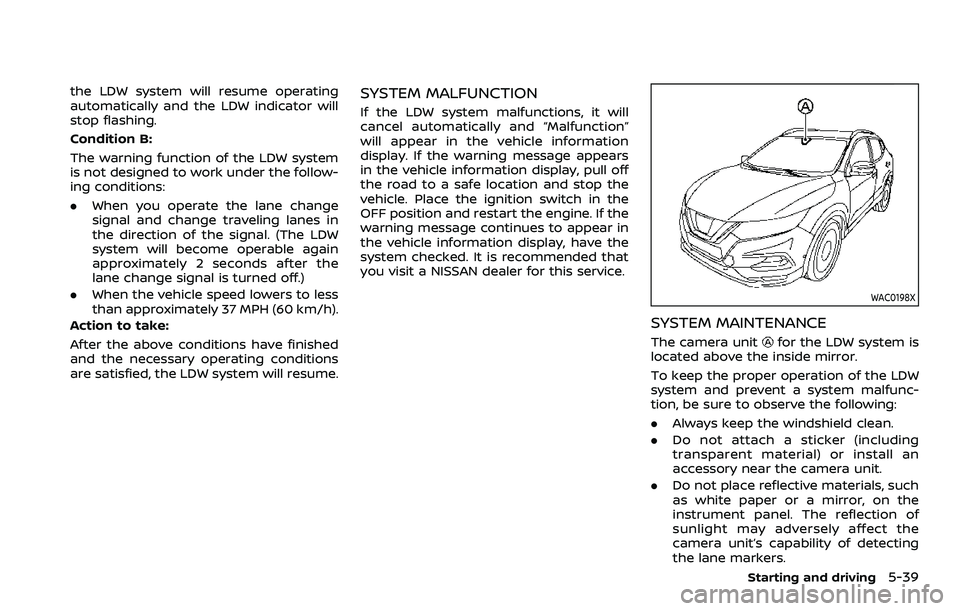
SYSTEM MAINTENANCE
The camera unitfor the LDW system is
located above the inside mirror.
To keep the proper operation of the LDW
system and prevent a system malfunc-
tion, be sure to observe the following:
. Always keep the windshield clean.
. Do not attach a sticker (including
transparent material) or install an
accessory near the camera unit.
. Do not place reflective materials, such
as white paper or a mirror, on the
instrument panel. The reflection of
sunlight may adversely affect the
camera unit’s capability of detecting
the lane markers.
Starting and driving5-39